PEBBLE - Picaxe Electronic Bread Board Layout Emulator
- Thread starter westaust55
- Start date
westaust55
Moderator
That last one is somewhat similar to one previously sold by Dick Smith Electronics (Australia) which I stocked up on when they went out of electronic components.
The 3 hole segments (in lieu of the more usual 5 hole segments) is ample for most work and helps keep overall proto board project size down.
Okay I will soon make a start to some of theses. The RS one's should be easy enough. The AXE091/92 may take a while.
The 3 hole segments (in lieu of the more usual 5 hole segments) is ample for most work and helps keep overall proto board project size down.
Okay I will soon make a start to some of theses. The RS one's should be easy enough. The AXE091/92 may take a while.
pepijndevos
Member
It would be great if it was possible to make resistors span more than 3 holes.
Why did you chose to make this a web app, but make people download it?
Why did you chose to make this a web app, but make people download it?
westaust55
Moderator
One way to extend a resistor is to use a grey wire overlapping one or both leads with the end towards the resistor body set to covered or not bare. Also if you right click on the component you can change the size (vertical,small, medium and large)
Some site do host the PEBBLE program online as a web app while others make it available for download.
Downloading the files can take a while so it can be easier for those with slower Internet or limited download capacities/limits to download the entire package once.
Some site do host the PEBBLE program online as a web app while others make it available for download.
Downloading the files can take a while so it can be easier for those with slower Internet or limited download capacities/limits to download the entire package once.
bannerman100
New Member
Hi there, I'm new here, so please bear with me if this has been asked before.
I have just downloaded Pebble V3.1. When I load a file created in version 2.5b, all the components appear two holes down and six spaces to the left of where they should be. The "Comp Up/Dn" functions don't correct the problem.
Any helpful ideas please ?
Thanks, Frank.
I have just downloaded Pebble V3.1. When I load a file created in version 2.5b, all the components appear two holes down and six spaces to the left of where they should be. The "Comp Up/Dn" functions don't correct the problem.
Any helpful ideas please ?
Thanks, Frank.
westaust55
Moderator
Hello Frank,
Welcome to the PICAXE forum.
From V2.5 (15Jan2010) to V3.0c (11Feb2010) there was a bug fix relating to layout file compatibility . From the Revision History file:
There was no further “offset” introduced in the more recent updates towards the current V3.1 (27Aug2011) which is now 8 revisions later than V2.5 and I have not seen any other report of an offset problem still occurring.
As this was now some 2 years ago, I suspect /guess that more recent versions may have subsequently deleted the bug fix with the thought that most people would likely have kept up to date with revisions.
Apologies, but at this time I suggest that you may have to manually move the components to correct their position if you are uploading some files created previously with V2.5.
Welcome to the PICAXE forum.
From V2.5 (15Jan2010) to V3.0c (11Feb2010) there was a bug fix relating to layout file compatibility . From the Revision History file:
I recall the fix was to detect the absence of a field in the loaded layout file and then correct automatically.3.0c 11 February 2010
Bug fixes to enable proper backward compatibility in loading circuit layouts from earlier versions
There was no further “offset” introduced in the more recent updates towards the current V3.1 (27Aug2011) which is now 8 revisions later than V2.5 and I have not seen any other report of an offset problem still occurring.
As this was now some 2 years ago, I suspect /guess that more recent versions may have subsequently deleted the bug fix with the thought that most people would likely have kept up to date with revisions.
Apologies, but at this time I suggest that you may have to manually move the components to correct their position if you are uploading some files created previously with V2.5.
westaust55
Moderator
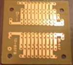
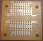
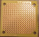
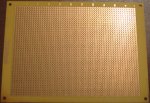
I made a start on adding the Radio Shack proto baords boards last night. Completed the 276-150 and started on the 276-168 (per post 684 above).I found one more board. I like this one a LOT.... I wish I knew how to do the boards.....
View attachment 10778
I did some (quick) thinking about how to consider/handle the various breakout boards.
As a mini breadboard (which seems a bit limited as the only board) or as a "component" which can be placed aligned over a breadboard or protoboard image.
My own thought are towards treating them as a component - like the existing 74LVC245A chip which being an SMD chip is shown on an SOIC to DIP adapter board.
Then you can line-up the breakout board with holes on the breadboard and even have multiple breakout boards visible at the same time.
I have not looked too closely at the hole positioning for the breakout boards but may need some artistic license so all holes are on a standard 0.1 inch / 2.54 mm grid to match with component lead and wire-end positioning abilities of PEBBLE.
westaust55
Moderator
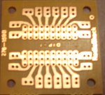
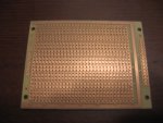
Might be time for some thoughts form those who use PEBBLE as to how to treat small PCBs which are basically little more than break-out boards for single IC's such as the boards forum member kollinsb has posted images of above.
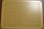
Having used a number of SOIC to DIP type adapters which are not much bigger in area than the equivalent DIP chip, when I drew up the first of the Radio Shack boards (276-159) as an image with holes to the same spacing as the PEBBLE grid (as per breadboards) I realised these Radio Shack single IC boards (well I guess you could also have two smaller DIP8 chips end to end) they are in fact quite large.
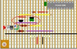
The attached image shows part of a large double breadboard with the radio Shack 376-159 board laid over the bread board and another in the bottom "off-board" area.
At this point looking for some thoughts from members who use PEBBLE as to:
1. The value in adding such a large single IC board to the library
2. Whether to treat as a breadboard in its own right or treat as a component that can be overlaid as per the attached image with IC/s placed over the top of the Radio Shack board
3. If the response to Q2 is to use as a "component" where an IC can be still placed over the top then have a plane grey board similar to an off-board area with some dots/crosses to indicate the grid position for "holes"
Point 3 is my thought/idea, but I will hold off for a few days to see what others may think.
Having used a number of SOIC to DIP type adapters which are not much bigger in area than the equivalent DIP chip, when I drew up the first of the Radio Shack boards (276-159) as an image with holes to the same spacing as the PEBBLE grid (as per breadboards) I realised these Radio Shack single IC boards (well I guess you could also have two smaller DIP8 chips end to end) they are in fact quite large.
The attached image shows part of a large double breadboard with the radio Shack 376-159 board laid over the bread board and another in the bottom "off-board" area.
At this point looking for some thoughts from members who use PEBBLE as to:
1. The value in adding such a large single IC board to the library
2. Whether to treat as a breadboard in its own right or treat as a component that can be overlaid as per the attached image with IC/s placed over the top of the Radio Shack board
3. If the response to Q2 is to use as a "component" where an IC can be still placed over the top then have a plane grey board similar to an off-board area with some dots/crosses to indicate the grid position for "holes"
Point 3 is my thought/idea, but I will hold off for a few days to see what others may think.
The board looks great! My humble opinion is to treat this one board as a component and give it the over/standard/under option that wires have. I believe this would take care of the issue of it taking up too much space as there will just be layers now as there are with the wiring.
I hope this makes sense. I really appreciate your work on the application!
kollinsb
I hope this makes sense. I really appreciate your work on the application!
kollinsb
Hi WestAust55,
Forgive me if I have missed it in this very long thread but I was wondering if i am able to add custom breadboards to the Pebble Library? I am working on some tutorial videos using a 17 x 10 breadboard from seeed studio and would like to put some pebble images together to help support the documentation / allow other people to add to my resources. I have generated a photo rendered .bmp from a CAD model and it could be modified if need be. The first few videos are on http://www.picaxeprotoplatform.com/videos/tutorials/ and I have attached the photo render via my website and also inserted a smaller jpeg. http://www.picaxeprotoplatform.com/wp-content/uploads/2012/07/Pebble-Image.bmp
If you cant add additional images, I will make do but it would be awesome (and a whole lot easier than drawing each of the components in CAD) if you could.
Cheers,
Joel
westaust55
Moderator
Yes, I can add you board shortly.
I had prepared images for a proto board and the AXE091 a month back but getting work completed on a new house and moving have occupied my time of recent. Should be back to a more normal life in a few days.
I had prepared images for a proto board and the AXE091 a month back but getting work completed on a new house and moving have occupied my time of recent. Should be back to a more normal life in a few days.
Last edited:
westaust55
Moderator
Hi all,
apologies for delays in any further updates.
It has been a case of a dose of the flu, then moving house and then more flu like symptoms for a week resulting from Whooping Cough vacine
@pilko and OrionBot,
can you advise which version of windows you are using.
Running Win XP and IE-8 here for example and components only go behind the board with IE-8 if I deliberately select P_for_FF.html as opposed to the PEBBLE.html to start
westaust55
Moderator
I have just fired up Win7 Pro (32-bit) on one of my older PC's and installed PEBBLE V3.1 direct from Rev Ed website (in case my version at home has something different).
I had no problems using either Mozilla FireFox or IE9.
Next, tried a newer PC with Win7 Home Premium (64-bit) where I already had PEBBLE V3.1 installed.
Again, I had no problems using either Mozilla FireFox or IE9.
Sole difference observed compared to Win XP is that the component edit pop-up windows display at the top right of the PEBBLE window, rather than just offset from the edge of the actual component being edited.
Suggests that maybe you have some unique setting on your version of Win7 or IE9 causing the components to go behind the board.
Last edited:
120ThingsIn20Years
Senior Member
problem with trying to place components
There are two line on my Pebble project where I cant place any components.
Any ideas why? I've reloaded it a few times but, no joy.
They are the two horizontal lines above the purple wire.
I'm using the online chrome version here ... http://www.robotgear.com.au/article.aspx/details?title=pebble
Using chrome Version 22.0.1229.94 Ubuntu 12.10 (161065)
I really like Pebble, but today it's driving me nuts
IC||458|799|1|PICAXE 20M2|U?|||PICAXE20|IC||PICAXE20_1
Miscell||568|846|1||XX?||1|36|||misc_36
Miscell||84|493|1||XX?||1|36|||misc_36
Miscell||595|846|1||XX?||1|36|||misc_36
Miscell||622|846|1||XX?||1|36|||misc_36
Miscell||676|846|1||XX?||1|36|||misc_36
Miscell||649|846|1||XX?||1|36|||misc_36
Miscell||460|846|1||XX?||1|36|||misc_36
Miscell||487|846|1||XX?||1|36|||misc_36
Miscell||514|846|1||XX?||1|36|||misc_36
Miscell||703|846|1||XX?||1|36|||misc_36
Miscell||541|846|1||XX?||1|36|||misc_36
Terminal||322|516|1||TS?||4|3|power ||terminal_341
LED|0|387|161|3|LED|LED?|1|||IC||led_13
Resistor|360|362|359|1|Resistor|R?||0||IC||
Miscell||111|493|1||XX?||1|36|||misc_36
Miscell||138|493|1||XX?||1|36|||misc_36
Miscell||245|493|1||XX?||1|36|||misc_36
Miscell||218|493|1||XX?||1|36|||misc_36
Miscell||191|493|1||XX?||1|36|||misc_36
Miscell||165|493|1||XX?||1|36|||misc_36
Miscell||353|493|1||XX?||1|36|||misc_36
Miscell||326|493|1||XX?||1|36|||misc_36
Miscell||299|493|1||XX?||1|36|||misc_36
Miscell||272|493|1||XX?||1|36|||misc_36
Miscell||460|493|1||XX?||1|36|||misc_36
Miscell||434|493|1||XX?||1|36|||misc_36
Miscell||407|493|1||XX?||1|36|||misc_36
Miscell||380|493|1||XX?||1|36|||misc_36
Wire||896|282|21||11|#000000|28|11||10|
Switch||327|163|2||SW?|2||2|Power||switch_222
Miscell||434|818|1||XX?||1|36|||misc_36
Miscell||595|493|1||XX?||1|36|||misc_36
Miscell||622|493|1||XX?||1|36|||misc_36
Wire||91|552|11||11|#000000|12|11||10|
Note||288|1140|2||||1||+ 5V rail||NOTEPAD_12
Wire||360|905|11||11|#FF0000|3|11||10|
Wire||441|769|11||11|#000000|1|11||10|
Capacitor||429|800|2|Capacitor|C?||1|1|||cap_112
Wire||441|905|11||11|#FF0000|1|11||10|
Wire||385|174|21||11|#FF0000|10|11||8|
Wire||412|174|21||11|#000000|10|11||8|
Miscell||514|493|1||XX?||1|36|||misc_36
Miscell||541|493|1||XX?||1|36|||misc_36
Miscell||568|493|1||XX?||1|36|||misc_36
Miscell||487|493|1||XX?||1|36|||misc_36
Terminal||591|516|1||TS?||5|3|Terminals||terminal_351
Terminal||591|461|1||TS?||5|4|Terminals||terminal_451
Note||148|338|2||||2||end of 2nd board||NOTEPAD_22
Miscell||326|628|1||XX?||1|36|||misc_36
Terminal||427|463|2||TS?||3|1|||terminal_132
Wire||414|579|11||11|#000000|1|11||10|
Wire||306|688|11||11|#FFFF00|3|11||10|
Wire||333|932|11||11|#FFFF00|6|11||10|
Miscell||57|493|1||XX?||1|36|||misc_36
Resistor|10000|381|611|2|Resistor|R?||1||IC||
Resistor|22000|308|902|1|Resistor|R?||0||IC||
Wire||387|660|11||11|#FFFF00|6|11||10|
Wire||37|1122|11||11|#000000|32|11||10|
Miscell||30|493|1||XX?||1|36|||misc_36
Miscell||864|384|1||XX?||1|36|||misc_36
Wire||412|1151|21||11|#000000|3|11||8|
Wire||387|606|11||11|#000000|1|11||10|
Miscell||676|493|1||XX?||1|36|||misc_36
Miscell||649|493|1||XX?||1|36|||misc_36
Miscell||703|493|1||XX?||1|36|||misc_36
Miscell||783|493|1||XX?||1|36|||misc_36
Miscell||756|493|1||XX?||1|36|||misc_36
Miscell||729|493|1||XX?||1|36|||misc_36
Miscell||864|411|1||XX?||1|36|||misc_36
Miscell||837|493|1||XX?||1|36|||misc_36
Miscell||810|493|1||XX?||1|36|||misc_36
Miscell||460|628|1||XX?||1|36|||misc_36
Miscell||514|628|1||XX?||1|36|||misc_36
Note||-14|522|2||||1||5V plug||NOTEPAD_12
Note||151|389|2||||2||front board hanging under at 90 deg||NOTEPAD_22
Miscell||864|357|1||XX?||1|36|||misc_36
Miscell||864|330|1||XX?||1|36|||misc_36
Miscell||380|574|1||XX?||1|36|||misc_36
Terminal||53|516|1||TS?||2|5|Terminals||terminal_521
Wire||118|606|11||11|#FF0000|8|11||10|
Miscell||864|493|1||XX?||1|36|||misc_36
Miscell||864|465|1||XX?||1|36|||misc_36
Miscell||864|438|1||XX?||1|36|||misc_36
Note||154|441|2||||2||Terminals are................ +5V 5V_or_0V LED+ OV||NOTEPAD_22
Wire||358|1151|21||11|#FF0000|3|11||10|
Note||423|1140|1||||1||0V rail||NOTEPAD_11
Note||424|168|1||||1||Power LED ||NOTEPAD_11
Note||147|287|2||||2||LED mounted outside project box||NOTEPAD_22
Miscell||299|330|1||XX?||1|36|||misc_36
Miscell||299|357|1||XX?||1|36|||misc_36
Miscell||299|384|1||XX?||1|36|||misc_36
Miscell||299|411|1||XX?||1|36|||misc_36
Miscell||299|438|1||XX?||1|36|||misc_36
Miscell||299|465|1||XX?||1|36|||misc_36
Terminal||376|434|1||TS?||2|5|||terminal_521
Wire||414|769|11||11|#000000|1|11||10|
Terminal||322|461|1||TS?||4|4|||terminal_441
Miscell||380|628|1||XX?||1|36|||misc_36
Miscell||434|818|1||XX?||1|36|||misc_36
Transistor|BC559|64|562|2|Transistor|Q?|||2|IC||transistor_22
Wire||89|255|21||11|#000000|10|11||10|
Wire||62|255|21||11|#FF0000|10|11||10|
Note||12|205|1||||2||Power supply||NOTEPAD_21
Miscell||84|628|1||XX?||1|36|||misc_36
Miscell||57|628|1||XX?||1|36|||misc_36
Miscell||111|628|1||XX?||1|36|||misc_36
Switch||27|1039|1||SW?|1||1|Feed Lever||switch_111
Miscell||487|927|1||XX?||1|36|||misc_36
Wire||145|1013|11||11|#A233C3|8|11||10|
Wire||172|932|11||11|#FFFF00|5|11||10|
Resistor|1000|147|1089|1|Resistor|R?||3||IC||
Wire||252|1095|11||11|#A233C3|10|11||10|
Resistor|10000|174|1035|1|Resistor|R?||3||IC||
Wire||279|1041|11||11|#FFFF00|5|11||10|
Miscell||138|1008|1||XX?||1|36|||misc_36
Miscell||30|1226|1||XX?||1|36|||misc_36
BREADBOARDSTYLE=BB48
SHOWTHETOPAREA=true
westaust55
Moderator
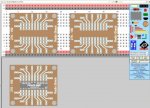
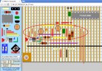
I have tried with IE and Chrome and cannot replicate your problem in terms on not being able to place components in the two lines above the purple wire. See attached image.
That said, your file as posted will not load as there are some formatting type errors.
For example this line has a space in the middle of the word "transistor"
and there is something wrong with these two line:
Terminal||591|516|1||TS?||5|3|Terminals||terminal_ 351
Terminal||591|461|1||TS?||5|4|Terminals||terminal_ 451adding either or both and all subsequent lines are not considered by PEBBLE.
Try uploading this attached text file version rather than posted into the main post to avoid adding hidden characters and work from there.
That said, your file as posted will not load as there are some formatting type errors.
For example this line has a space in the middle of the word "transistor"
Transistor|BC559|64|562|2|Transistor|Q?|||2|IC||tr ansistor_22
and there is something wrong with these two line:
Terminal||591|516|1||TS?||5|3|Terminals||terminal_ 351
Terminal||591|461|1||TS?||5|4|Terminals||terminal_ 451
Try uploading this attached text file version rather than posted into the main post to avoid adding hidden characters and work from there.
Attachments
-
 91 KB Views: 23
 -
4.9 KB Views: 8
120ThingsIn20Years
Senior Member
Thanks, it might be something to do with carrige returns on linux or something,
I cant get my copy to load any more, except for a few components,
Ill look for those errors, and any others like it.
And point taken re file upload.
Thanks again.
I cant get my copy to load any more, except for a few components,
Ill look for those errors, and any others like it.
And point taken re file upload.
Thanks again.
westaust55
Moderator
It is also recommeded to download the Version 3.1 which is available from the Rev Ed website here: http://www.picaxe.com/Software/Third-Party/PEBBLE/#download
Some of the organisations who initially hosted PEBBLE at earlier versions have seemingly dropped by the wayside and still have older versions on their sites.
Post 1 of this thread endeavours to show who is hosting which version.
I had started to work on adding the AXE091 board some time ago but found the image size too big for most normal PC displays so one would have had to scroll heavily
to work with the board/image within PEBBLE. Following a house move mid-2012 various matters have arisen here that slowed that down progress on an number of things.
120ThingsIn20Years
Senior Member
Thanks. I got the latest version and installed it on my system. It now loads (from your text file) and shows all the components, but I still get the two lines that wont accept components. It's as if the lines above and below are magnetic. There's a "snap to grid" at work, so I wonder if it has something to do with that.Is there any way the method you use to attract parts to the holes in the board might be doing something funny?
sorry about the quality, but this video is the best I could do...
http://youtu.be/0BAlcbDCQKc (video only works from this link, so nobody will see it out of context)
sorry about the quality, but this video is the best I could do...
http://youtu.be/0BAlcbDCQKc (video only works from this link, so nobody will see it out of context)
120ThingsIn20Years
Senior Member
A little more information.
When I add a vertical wire, the bottom of the wire can be stuck on those two problem horizontal lines, but the top of the wire cant.
When I add a vertical wire, the bottom of the wire can be stuck on those two problem horizontal lines, but the top of the wire cant.
westaust55
Moderator
I watched your video clip and from that I would initially surmise that the PEBBLE program script for defining rows and columns of holes was omitting those lines.
Yet when I try with V3.1, I am not able to replicate the mentioned problem with IE or Chrome.
Attached is a screen grab clip showing various wires and components with the top starting in the two rows in question.
Have you downloaded the V3.1 from the Rev Ed website?
EDIT:
My earlier tests were done with Win XP SP3.
I have just downloaded V3.1 from the Rev Ed website onto a PC running Win7 Home Premium 64-bit and still have no problems placing components with the top or left corner in the two rows above your purple wire using Mozilla Firefox (Chrome not installed on this PC).
Attachments
-
 145.4 KB Views: 13
Last edited:
120ThingsIn20Years
Senior Member
I just reinstalled the latest version from rev ed, dropped your text file in, and it works. I have no idea why or what I did wrong, but I have several versions of pebble. Perhaps I was using a latest version txt file on ver 3.0 or something confusing. But it all works since the fresh install.
Sorry for being a pain in the butt, and thanks again for an excellent program. and your kind support.
Sorry for being a pain in the butt, and thanks again for an excellent program. and your kind support.
120ThingsIn20Years
Senior Member
And just for your record, those spaces in those terminal lines were as copied. ie I didn't hand edit the text file or anything. None of it means anything to me so I wouldn't even think to edit it.
But I do recall from ages ago, I had an issue with moving code written in linAXEpad to the normal picaxe program editor in windows, and there was some issue with carriage returns, and I think spaces. I seem to remember this was something to do with the Linux way vrs the Windows way of dealing with the return key.
Both the problem version of my Pebble project, and the one that works, were all created on Chrome, and Ubuntu linux. There is a chance I made the files in Pebble ver 3.1 and ran them later on 3.0.
Sorry I cant be more certain.
I have been trialling PEBBLE and getting on quite well with it. It has an appropriate level complexity when you just want to play around to find a neat stripboard layout.
Suggested enhancements from me would be:
Rotate program socket 90 degrees to point right or left, accross the strips. This would always require a break in the strip between the SI and 0V connectors.
More options to make use of the long leads on resistors and capacitors to span longer gaps. This would be better than "faking" it with adjacent grey wires.
Thanks Westy for a very useful little tool.
Paul
westaust55
Moderator
Hello Paul,
Yes, I should get in and do some more with PEBBLE some time soon – so many things to do and so little time seems to be the problem. I had started on some additional almost a year ago now but got distracted with moving to a new house, then my PC hard drive failed and while I had the vast majority of my work backed up on a separate external HDD that unfortunately did not include the very latest additions to PEBBLE at that time.
More recently a motherboard failure - which coincided with severe lightning storm over the house.
I will have to go back and see where I was at and try to restart form that point.
I had amongst other things been looking at having a board being the entire AXE091 but at the scale involved this was going to be far to big to display the entire board onto the presumed average PC screen (assumed at around 19inch).
Might be a good time to also see if others have any favourite IC’s often used/mentioned on the forum that they might like to see included.
120ThingsIn20Years
Senior Member
There is an excellent free service from ubuntu (linux) that also runs on any other platform that will backup in real time whatever folders you point it to.
https://one.ubuntu.com/
Totally free for 5gig of cloud storage. (and it has been for years)
As you drop a new file or edit an existing file in the selected folders, it syncs with the cloud server, and places a little green tick on your files to say they are synced. The tick is the only trace that anything is happening (ie you don't have to do anything).
If your system fails, all you have to do is install the software on your new system, enter your user name and password, and your old files re-appear.
It also deals with book marks and stored passwords.
I had a system fall over, and it felt very good when I saw all my old files, all up to the minute, restored to my desktop.
It's also useful to make your desktop and laptop talk to each other, or home and work systems.
westaust55
Moderator
Thanks for the suggestion however, I had long ago made a deliberate decision not to use such services for various reasons. Some PEBBLE work was all that I lost as a result of a HDD fail. All other working data and files are kept on a separate drive partitions ( D: and E: ) which I kept backed up. It was just that the more recent PEBBLE work which I kept in a working folder on the C: drive that was lost.
At the subsequent time my when my motherboard failed, purchase of new parts had my PC it up and running (and faster) but it was 3 weeks (yes 21 days!) before I had telephone and internet services back again at home. Rather dismal in fact. (Keep in mind here that I had been reporting to Telstra directly that I believed they need to do some work on the street pit near my house for 6 months!)
The failed telephone/ADSL line was reported to our ISP and telephone provider who reported the line problem to Telstra Australia who maintain the street cabling. Telstra claimed the line was okay and the fault was in our (new) house and it would cost us if they were to test further and the fault was found to be in our house. We purchase a new ADSL filter and an extra hand set which did not resolve the problem and took both old and new handsets to relative’s house where they worked perfectly. More calls to Telstra and eventually the fault was found in a street cable pit further down our street.
Had I been reliant upon external services for my back-up procedures that would not have happened during the three weeks in question – but I was still able to use my external HDDs for PC rebuild and ongoing back up.
However we digress, so back to asking folks if they have any other favourite IC’s often used/mentioned on the forum that they might like to see included.
120ThingsIn20Years
Senior Member
I've been there.
There's not a lot you can do in that situation.
I spent 2 years getting free net access (except when we accidentally paid for one month) because they couldn't create "one good bill in a row" (my phrase) that reflected my Internet access (it turns out you don't have to pay for it if it isn't delivered according to the contract )
But if you ever get reliable service, the cloud stuff is really worth while.
I also backup to an external hard drive, but it's so nice having the service that just restores your desktop, bookmarks, and passwords.
There's not a lot you can do in that situation.
I spent 2 years getting free net access (except when we accidentally paid for one month) because they couldn't create "one good bill in a row" (my phrase) that reflected my Internet access (it turns out you don't have to pay for it if it isn't delivered according to the contract
)But if you ever get reliable service, the cloud stuff is really worth while.
I also backup to an external hard drive, but it's so nice having the service that just restores your desktop, bookmarks, and passwords.
Might be a good time to also see if others have any favourite IC’s often used/mentioned on the forum that they might like to see included.
- MAX7219/21
- 16x2 LCD. Most common seem to have 16 pins in horizontal line along the top edge and measure 3.2" x 1.4" (apologies for the non-metric units)
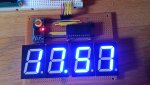
Also, could we have stripboard up to 46 strips wide please? (Current limit is 43). I have used this a few times, such as this example where 4 x 1.2" 7-seg displays needed to be mounted:
Last edited:
Hi Westy,Yes, I should get in and do some more with PEBBLE some time soon – so many things to do and so little time.....
Yes Indeed. I'm also an enthusiastic Pebble user and endorse ALL of Paul's comments/suggestions in #711, but refrained from asking as perhaps you have better things to do. I think I've read most of the 72 pages of posts but couldn't find a "Guide" to explain how to add new components (at least for anyone, like me, without Java or HTML, etc. experience)?
I had no difficulty rotating the images of the programming socket, but the pins didn't align properly with the board matrix (and anyway I would like all 4 orientations to be available). Similarly, no problem adding pin names to a "blank" package outline, but there's only one of each size, could there be a few more "generic" outlines for us to modify (if extending the "library" of images is difficult)?
Then, only slightly contrary to Paul's last suggestion, could you support boards of less than 10 holes, since some of my layouts (e.g. a programming adapter) need less than 10 holes on one axis.
And a final comment (probably more difficult to fix); it's difficult to access the lower parts of the "floating" (or "buoyant") menu on my Netbook, since its screen has only 600 pixels in the vertical axis.
Thanks for the very useful application, Alan.
My first moderate-sized effort with Pebble:
View attachment mozilla.pdf
View attachment mozilla.pdf
Code:
IC||406|468|2||U?|||PICAXE20M2|IC||PICAXE20M2_2
Resistor|10000|606|377|1|Resistor|R?||3||IC||
Resistor|22000|956|432|1|Resistor|R?||3||IC||
Wire||1035|492|11||11|#3253FF|1|11||10|
IC||379|1038|2||U?|||ULN2803|IC||ULN2803_2
Wire||712|383|11||11|#999999|3|11||10|
Terminal||243|619|1||TS?||6|3|LCD||terminal_361
Wire||281|764|11||11|#FF0000|16|11||10|
Wire||227|655|11||11|#FF0000|2|11||10|
Miscell||247|786|1||XX?||1|36|||misc_36
Wire||281|1008|11||11|#000000|4|11||10|
Resistor|4700|229|866|1|Resistor|R?||3||IC||
Resistor|4700|768|1247|1|Resistor|R?||2||IC||
Wire||11|845|11||11|#00A060|9|11||10|
Wire||334|818|11||11|#00A060|5|11||10|
Miscell||139|623|1||XX?||1|43|||misc_43
Miscell||327|786|1||XX?||1|36|||misc_36
Miscell||408|867|1||XX?||1|36|||misc_36
Miscell||624|1084|1||XX?||1|36|||misc_36
Miscell||651|1084|1||XX?||1|36|||misc_36
Terminal||216|1243|1||TS?||6|3|I2C||terminal_361
Miscell||605|280|1||XX?||1|1|Miscell||misc_1
Resistor|10000|929|460|1|Resistor|R?||3||IC||
Transistor|BC559|739|1208|2|bc337 npn|Q?|||1|IC||transistor_12
Resistor|4700|229|813|1|Resistor|R?||2||IC||
Wire||658|1008|11||11|#000000|5|11||10|
Transistor|BC559|631|1208|2|bc327 pnp|Q?|||1|IC||transistor_12
Resistor|4700|660|1248|1|Resistor|R?||2||IC||
Miscell||300|786|1||XX?||1|36|||misc_36
Wire||361|1144|11||11|#FF9900|1|11||10|
Terminal||377|1216|1||TS?||4|3|LEDs||terminal_341
Terminal||377|1243|1||TS?||4|3|LEDs||terminal_341
Terminal||485|1243|1||TS?||6|3|Solenoids||terminal_361
Miscell||1082|1193|1||XX?||1|36|||misc_36
Miscell||1136|1193|1||XX?||1|36|||misc_36
Miscell||1109|1193|1||XX?||1|36|||misc_36
Miscell||1136|297|1||XX?||1|36|||misc_36
Miscell||1082|297|1||XX?||1|36|||misc_36
Miscell||1109|297|1||XX?||1|36|||misc_36
Miscell||1136|351|1||XX?||1|36|||misc_36
Miscell||1136|324|1||XX?||1|36|||misc_36
Miscell||1082|324|1||XX?||1|36|||misc_36
Miscell||1082|351|1||XX?||1|36|||misc_36
Miscell||1109|351|1||XX?||1|36|||misc_36
Miscell||1082|1220|1||XX?||1|36|||misc_36
Miscell||1082|1247|1||XX?||1|36|||misc_36
Miscell||1109|1247|1||XX?||1|36|||misc_36
Miscell||1136|1247|1||XX?||1|36|||misc_36
Miscell||1136|1220|1||XX?||1|36|||misc_36
Miscell||435|867|1||XX?||1|36|||misc_36
Wire||793|981|11||11|#000000|6|11||10|
Wire||388|1171|11||11|#FF9900|11|11||10|
Wire||65|386|11||11|#FFFF00|16|11||10|
Wire||334|682|11||11|#FFFF00|4|11||10|
Wire||388|981|11||11|#000000|10|11||10|
Wire||415|329|11||11|#00A060|16|11||10|
Terminal||940|267|2||TS?||3|1|Program||terminal_132
Capacitor|100n|282|1161|1|Capacitor|C?||2|1|||cap_121
Miscell||974|623|1||XX?||1|43|||misc_43
Miscell||139|976|1||XX?||1|43|||misc_43
Miscell||462|867|1||XX?||1|36|||misc_36
Wire||631|411|11||11|#3253FF|11|11||10|
Wire||631|574|11||11|#3253FF|14|11||10|
Wire||281|682|11||11|#999999|1|11||10|
Wire||173|709|11||11|#000000|3|11||10|
Terminal||81|1135|1||TS?||4|3|Power||terminal_341
Wire||92|1117|11||11|#FF9900|10|11||10|
Miscell||974|976|1||XX?||1|43|||misc_43
Transistor|BC559|146|1009|1|78L05|Q?|||1|IC||transistor_11
Wire||200|1089|11||11|#FF0000|1|11||10|
Wire||173|981|11||11|#000000|4|11||10|
Capacitor|100n|659|591|1|Capacitor|C?||1|1|||cap_111
Capacitor|100n|174|1025|1|Capacitor|C?||1|1|||cap_111
Capacitor|100u|93|1034|1|Capacitor|C?||3|3|||cap_331
Terminal||485|1379|1||TS?||3|3|Power||terminal_331
Terminal||647|1433|1||TS?||3|3|Power||terminal_331
Terminal||755|1406|1||TS?||3|3|Power||terminal_331
Capacitor|100n|93|1079|1|Capacitor|C?||2|1|||cap_121
Miscell||624|596|1||XX?||1|36|||misc_36
Capacitor|100u|228|1045|1|Capacitor|C?||2|3|||cap_321
Wire||658|438|11||11|#FF0000|2|11||10|
Terminal||512|619|1||TS?||6|3|LCD||terminal_361
Resistor|100|633|677|1|Resistor|R?||2||IC||
Wire||388|709|11||11|#FFFF00|4|11||10|
Wire||254|736|11||11|#000000|4|11||10|
Resistor|1500|175|676|1|Resistor|R?||3||IC||
Wire||954|492|11||11|#000000|1|11||10|
Wire||307|845|11||11|#00A060|4|11||10|
Wire||92|356|11||11|#FFFF00|17|11||10|
Wire||38|411|11||11|#FFFF00|16|11||10|
Wire||38|899|11||11|#FFFF00|14|11||10|
Wire||92|954|11||11|#FFFF00|14|11||10|
Wire||65|926|11||11|#FFFF00|14|11||10|
Wire||11|438|11||11|#00A060|19|11||10|
Miscell||274|786|1||XX?||1|36|||misc_36
Miscell||354|786|1||XX?||1|36|||misc_36
Miscell||381|786|1||XX?||1|36|||misc_36
Terminal||81|1162|1||TS?||4|3|Power||terminal_341
Terminal||81|1189|1||TS?||4|3|Power||terminal_341
Terminal||81|1216|1||TS?||4|3|Power||terminal_341
Terminal||81|1243|1||TS?||4|3|Power||terminal_341
Wire||92|1008|11||11|#999999|2|11||10|
Miscell||85|976|1||XX?||1|36|||misc_36
BREADBOARDSTYLE=BB55=43=36
SHOWTHETOPAREA=true
Last edited:
Hi,
Here's a stripboard layout that I'm currently designing with Pebble, which shows some of the work-arounds that I've adopted to overcome its minor limitations. Pebble is ideal because, although I hope that the overall design may be (ultimately) reproduced a number of times, I don't expect to ever design a PCB. Reasons are cost and because various derivatives may be required, e.g. with a programming socket added and perhaps using larger chips such as 14M2 or even 20M2.
Firstly, the board is only 16 x 8 holes (smaller than Pebble directly supports) so I've marked its outline with four violet "wires". But it's not a bad idea to have some additional holes around the edge when experimenting with a layout, so that one can "walk" groups of components around the board without them "falling off the edge". Also the "signal labels" can use the extra space. Anyone who instantly reads resistor colour codes may spot that 9k1 10k and 11k resistors are all shown. Actually they're all 10k but here I've used slightly different values for identification, since IDs are not available (and probably would over-complicate the diagram).
Normally, when I need to connect two adjacent tracks, I don't bother with a "U" link, but just fold a component lead onto the adjacent track underneath, then crop, before soldering. I've shown this on the Pebble Layout as a white U-link, for example from the electrolytic +ve lead to PICaxe Leg 1. In this circuit the transistor is only an "optional" component, but it would be nice to have the normal 90/45/45 degree "triangular" footprints, ideally with both "1E" (0.1 inch) "short" sides and 2E long hypoteneuse versions.
The main technique that I use to keep the size down is to cut the tracks between holes (shown with a "CUT" symbol), rather than use a spot-face cutter. It's easy to do, just make two parallel cuts about 1mm apart with a craft knife or scalpel and then "pop-off" the copper in-between with the tip of a hot soldering iron. However, it's also possible to use a spot-face cutter: A component can be inserted through a "cut" hole and then the wire folded onto the appropriate copper track and soldered as above (but again a new symbol to show this would be useful). I tried modifying the "NC" graphic file (misc_43.GIF) in various ways but couldn't make it centralise between holes, so ended up modifying the "vertical bridge" symbol (misc_35).
Ultimately, I resorted to one "cheat" (insulated wire): However, the Blue wire could be replaced by an extra copper track to the left (and two links), or be avoided altogether by exchanging the SerOut and Ramp connector pin functions (they may end up all wired into a single CAT5 cable anyway). If really short of space, the yellow wire might go under the PICaxe to save a row of "holes". Sometimes, I use a "diagonal" link (e.g. the Orange wire) which is rather easier to wire on the board than it is to draw in Pebble (but at least it can be shown).
Finally, don't try to work out what this circuit is actually supposed to do! Not only will most of the PICaxe pins be driven either Low, High or Tristate/input in various permutations, but the software is planned to control the internal Voltage Reference Divider chain, two Comparator inputs and its output, SR-flipflop, T1Gate Control and the Weak Pullup resistors of the raw PIC chip. Oh, and "Vcc" isn't the power supply rail (except perhaps when programming the PICaxe) and the LED isn't a LED.
Cheers, Alan.
Attachments
-
 193.1 KB Views: 45
Howardandhopkins
New Member
Hi Westy
I also find Pebble very useful and would, if there was a guide available, be happy to contribute new IC's or components. I'm sure there would be many people who would contribute back and maybe this could then be moderated and distributed back out to the community.
As already said its a very useful tool so thanks for putting in the work to make it as good as it is
Ian