PEBBLE - Picaxe Electronic Bread Board Layout Emulator

westaust55

Moderator
@Howardandhopkins (Ian),

Welcome to the PICAXE forum.


For all,

Thanks for the feedback and suggestions.
I have recently added some extra chips to my DIPTRACE library (yet to be uploaded) and will shortly add these to PEBBLE as well. They are/include the MAX7219, WS2801 & WS2803, PT6961.

I have been relatively busy completing work around a new house and in recent months working on a new project involving longer working hours. However, it is my intent to get back into PEBBLE soon and incorporate the bits I have and the suggestions put forward by other members where feasible.
 

manuka

Senior Member
Westie: I've penned an educationally slanted "Thinking inside the box" article for SiChip's Jan 2014 issue,with power by a single AA sized 3.2V LiFePO4 cell. (Thanks to some arm twisting Jaycar are soon to stock these).

Some of the board slices used are fibreglass based KPB (Kiwi Patch Board), but this gets costly for small versions - it's wasteful to slice & dice a nifty KPB for trivial needs! For skinflints & schools I've hence also considered Jaycar's HP9556 & HP9558 Paxolin, which can yield up to 5-10 boards from a single ~$3-$5 purchase. When deeply scored on both sides they'll crack apart nicely, & rough edges can be quickly sanded smooth. A quick spray of clear protective coating prevents track tarnishing & aids soldering nicely.

Sure - the resulting board is not that professional,but it's logical/neat/cheap/quick & it's compact layout alerts assemblers to today's tight circuitry. Of course circuits developed via a "tame on a solderless breadboard first - then lift over to solder on circuit board" approach usually WORK = a great confidence booster for newbies. In contrast the confusion associated with the (sadly) still all to common rats nest layouts can be disheartening...

OK - you've of course the HP9556 as a PEBBLE board option (3rd down on PEBBLE Ver 3.1) -the HTML source code shows this as <option value="BB56">20R 2Pwr-rail Jaycar HP9556 ProtoBrd However Jaycar's HP9558 board, with 3 a side (+ outer & centre rails) probably better suits breadboard matching than the HP9556. PEBBLE's optioned DSE H5608 is close to this, but it's now near historic as Dick Smith have of course virtually dropped all components. Jaycar in contrast are surging ahead.

Any chance hence of adding this HP9558 "finger",perhaps 20 x10 sized, as a PEBBLE option to match the article? 2014 newbies will no doubt appreciate the convenience & naturally I give you credit! Refer a quick 18 x 10 mockup (rustled up with a graphics editor) to show what I'd in mind. Regards-Stan.
 

Attachments

Last edited:

westaust55

Moderator
Hello manuka/Stan,
I have been quite busy with extended laying work (still am in fact) and eye problems (now sorted) so a few PEBBLE additions have not come to fruition. In view of you forthcoming article I will look at doing as a zip file patch rather then a full new package and russle something in in next few days all being well.

As for the DSE boards. The one I have used a lot I still have about 20 or so left.
I did find a site that sold the same board but neglected to bookmark the webpage, so now have not been able to locate again :(
 

manuka

Senior Member
Westie: Many thanks - appreciated! Trust that 18 x 10 sample above suits (but maybe make it 20 x 10 ) ? I can host any tweaked PEBBLE for SiChip readers OK.

Sorry re your eye woes - I'm recovering from a sudden detached retina myself,so can keenly relate to such afflictions... Stan.
 

geoff07

Senior Member
Just a thought for when you have an idle moment (if ever), but on the breadboard itself, how about a faint trace indicating which holes are connected and which not? It isn't very obvious to a beginner (actually, on my real BB the underlying connections aren't marked at all) and even I have occasional moments of doubt.

As for ready-made pcb images as a basis, Radioshack do a few quite useful ones - 276-159B, 276-150, and 276-168B all being worth a look.
 

geoff07

Senior Member
Well, yes there are other similar ones, but they don't look quite like a straightforward BB of the white plastic kind. I always found it odd that the BBs themselves don't indicate how they are connected.
 

manuka

Senior Member
Good point -I've long found newbies are confused by the "sea of holes",but most quickly wise up when a breadboard back is partially peeled away & contacts are revealed.

Extra: A 20x10 "finger" mockup shown (c/w programming input) laid out for 08M2 applications.
 

Attachments

Last edited:

geoff07

Senior Member
I thought I would try using Pebble for a little stripboard project. And tripped over two questions I can't answer, though maybe the answers are really obvious to others, and apologies if these questions have already been asked and answered but I gave up on scanning 73 pages of info!

- how to orient the strips horizontally? I have always thought horizontally when using stripboard. Vertical strips don't feel intuitive to me.
- how to indicate a break to be made in a strip? I thought of using a single-pin terminal, but they aren't allowed and I couldn't find any other single-hole part.

Of course, these aren't issues when using a breadboard.
 

AllyCat

Senior Member
Hi geoff,

At the foot of the Miscellaneous pull-down list (headed by a LDR) is a "Stripboard Track Cut" symbol and also a single "Test Pin". However, personally, I often cut tracks between the holes (using a craft knife) for a more compact construction. It is possible to modify existing symbols using a "paint" package (I have added pin names to a blank DIL package, rotated the Programming socket and created a "Track Cut" symbol for my own layouts).

However, I haven't found any descriptions of how to add new items to the library, nor how to make modified (e.g. rotated) symbols align with the grid. Obviously some of the components need complex coding to add into the library, so it would be useful to have a few "blank" symbols which could have their images modified.

Unfortunately, Westie is now very busy with "real" work. He still contributes to the forum, but it appears mainly from an iPad, which probably isn't much use for developing Pebble. There are probably several of us who would be prepared to put in some time adding to the library, but we need to know how to do it (and unfortunately I have no knowledge of HTML or Java, etc.).

By chance, I also wanted to design a "horizontal" stripboard yesterday (to add onto an existing PCB), but I think the problem is that it's not simply a matter of adding/rotating a single graphic image. A high proportion of the symbols are specifically designed to connect between vertical tracks (on stripboard and/or Solderless Breadboard) and would need to be duplicated for horizontal connections.

Cheers, Alan.
 

geoff07

Senior Member
Thanks for pointing out the track cut. And I thought that was just an ldr!

That's the trouble with good ideas - they take on a life of their own. Real (i.e. paid) work = good.
 

westaust55

Moderator
I have over a couple of evenings last week generated the image a code to include the "finger board" as sought by manuka.

I did about 18 months ago prior to a house move and PC failure (lightning strike directly over new house) create the graphic for some smaller Tandy/Radio shack boards. I will try to locate or recreate those as before I generate a patch file for PEBBLE.

Alan is correct that to make use of a strip board data text through 90 degrees there is also a need to generate graphics for most components. Resistors and wires are drawn on the fly but most other components are discrete graphics.

Unfortunately not an iPad just the iPhone so Screen Size and typing window is small - along with eyesight and auto spell crosscut can result in some novel words/spelling. :)
 
Last edited:

wainon

New Member
Hello

What a great application for documenting and laying out circuits, etc.

I recently needed to include two 3 way Screw Terminals oriented 90 deg to the existing ones and could not find any information about how to modify or add components. So have outlined the method I used and apologize if the following has already been posted. If not, it may help others in the same predicament.

My first successful effort replaced two existing terminals with the type I required by modifying their image in IfranView editor to that required. However, it meant choosing between either my modified version or the original which could be inconvenient next time Pebble was needed. I felt there must be a way to add simple components but it took a lot of "head scratching" and experimenting to achieve it it.

Here is how I added the two re-oriented terminals in a permanent manner.

*******

First I added the two new images to the image folder as misc_44.gif and misc_45.gif for access from the miscellaneous menu, which proved to be easier than adding to the terminal section. On my original copy misc items go up to 43

Two Pebble files imagedata.js and pebble.html (or which ever file is used to call up Pebble in the browser) need to be modified as follows. In the HTML file two line with the new menu item and image number are added in the misc section just before "</select></td>".

<option value="44">
<script language="javascript">document.writeln(_("3 way Terminal VL"));</script>
</option>
<option value="45">
<script language="javascript">document.writeln(_("3 way Terminal VR"));</script>
</option>

Being the menu labels (3 way Terminal VL & R), now the last items in the miscell menu, and images for the new vertical left and right handed terminals.

Unfortunately, the above alone will not add the component, as it appears to be "registered" in the javascript file imagedata.js. So these additions also need to be added to that file, under misc, as well.

var misc_44 = new Image();
var misc_45 = new Image();

and

misc_44.src = "images/misc_44.gif";
misc_45.src = "images/misc_45.gif";

The above modifications allow the new images to be shown on the bread board. While they may not be aligned perfectly they are close enough to give a good visual indication.

I hope the above is useful to anyone wanting a simple additional component. No doubt some one with Javascript experience could explain it more fully.

Thanks for a very useful program

Wainon
 

westaust55

Moderator
PEBBLE - Some Documentation - How to add a breadboard

Finally after a number of years I have started to put some words together explaining how to add items to PEBBLE.

The first part provided herein covers how to add your own breadboard or proto-board.
It has all been "stored' in my "Grey matter" and hopefully I have all the aspects and variable definitions correct in the description.


EDIT: I have removed the instructions at this post. Please see post 785 for a new files with minor amendments.
 
Last edited:

sedeap

Senior Member
PEBBLE OnLine with Spanish lang available from Argentina

Hi WestAust55.... long time ago...
But PEBBLE still alive... hahaha....
Translation to Spanish is available as usual...
And the URL to our OnLine PEBBLE is:
http://pebble.my-board.org
:rolleyes:


lbenson

Senior Member
I also use Pebble regularly. Thank you for the program, and thanks especially for any documentation about how to add or re-orient parts.
 

westaust55

Moderator
Thanks for the feedback folks.

Currently working on an update to PEBBLE to include a new prototyping board, a few new ICs I have been using and some strip/protoboard parts/edit items suggested by Allycat (Alan) along with a few other edits and fixes.
Will upload a "patch" zip file soon for folks to try out before sending out a full zip file as a new version.

Again, if these are any ICs or other parts that folks regularly use that warrant including let me know and can look to including same into the current update - while I am quiet on the paying work front.
 

westaust55

Moderator
Hi WestAust55.... long time ago...
But PEBBLE still alive... hahaha....
Translation to Spanish is available as usual...
And the URL to our OnLine PEBBLE is:
http://pebble.my-board.org
:rolleyes:

Thanks sedeap.
I thought we already had that spanish/Castellano language file included but on checking was not there :eek:
copied from your site and should be included in the next update.

Regards
westaust55
 

OC71

New Member
Pebble labels

@ westaust55
Can you create a small label 0.1" x 0.1" capable of accepting up to 3 characters. I am showing the bodges that I use to explain
what I mean.
 

Attachments

AllyCat

Senior Member
Hi,

Yes, that could be useful, and I'd just been thinking that a "Medium-sized Note" with an up/down (or no) "pointer" would be useful. Perhaps large enough for two lines of text but only 2 or 3 tracks wide (i.e. similar in width to the present Small sideways pointer.

If an up/down pointer is required, it might be synthesised in the top or bottom text line with a caret (^) or slashes ( \/ or /\ ) and of course sideways with a < or > .

Cheers, Alan.
 

westaust55

Moderator
@ westaust55
Can you create a small label 0.1" x 0.1" capable of accepting up to 3 characters. I am showing the bodges that I use to explain
what I mean.
Hello OC71,

that topic is rectified :), see the attached

MicroTag.gif.
Box width is a compromise as many 3 character combinations will be narrower but "WWW" will overflow to the right.
Reduced the text size down from 9 point (as used in other notes) to 8 point to help achieve an approx 0.1" / 2.54 mm box width (relative to bread/strip/protoboards

The menu includes a new "medium sized" note selection in line with Allycat's request but will code that tomorrow

As I will be busy elsewhere Wed and Thurs this week I will look to uploading an interim update zip file of all updates done in recent days for folks to try and advise any bug reports.
Still to look at reducing the selection area below IC images and add a few more components for Allycat.
 

westaust55

Moderator
I have modified the "Micro" Note/Tag a little this morning.
Where the small and large tags have left and right pointers, the micro note/tag is just a rectangle (as per above post).
But now, the Note window icons are slightly modified and if you select the second (right pointing) orientation the micro note/tag is orientated vertically.
Thus you can have:
(a) 1 row of 3 characters, or
(b) 3 rows of 1 character. For the 3 rows of 1 character you need to put a space between each of the characters to move to the new line (eg "E B C")

This might be helpful for some vertically orientated device such as transistors added for allycat.

Micro_Tag2.gif

EDIT: The full range of Notes are now as per the following image:
Notes in 4 sizes.gif
 
Last edited:

westaust55

Moderator
Attached are two compressed/zip file containing all of my updates since PEBBLE V3.1 as hosted on the Rev Ed website.

EDIT: The V3.1c update files have been deleted here for size reasons. - See post 758 for the latest V3.1e files

Two files attached due to zip file size limitation of the PICAXE forum.

PartA contains everything except the image for the new breadboard Datak 12-600B which is a large file.
PartB only has the image for the Datak 12-600B proto-typing board - so not essential if you do not want to use that board.

Unzip (open the zip) and copy the contents (files and folders) as they are from the two zip files into your folder where you currently have PEBBLE installed.

If folks try out this update and let me know any bugs aor comments in the next few days would be good.
I still have some additional work to do on the coming weekend to add some further parts for allycat.
Then I may hopefully get back to writing some more words on how to add your own components to PEBBLE.


@sedeap,
Once I have the remaining parts added I may call upon your assistance with some further English to Spanish translations for the new text parts.


The fixes and additions thus far are as follows:


3.1b 16 Aug 2016
Fixed bug for wires where a copied wire did not copy across all the parameters for insulated wire ends
Fixed bug to correctly display the AXE029 module when selected for the 28/40 pin PICAXE parts
Localisation file for Castellano (Spanish) included (courtesy of PICAXE forum member Sedeap)
Increased the range of permissible sizes for the General Strip board. Now 6 to 50 holes wide and 10 to 71 holes high.
Added Datak 12-600B Proto-Board
Added LV8549MC SOIC Dual H-Bridge (suit smaller stepper motors and simple motor controllers)
Added two new transistor orientations with the legs all vertically orientated (best for strip/proto board work)
Added two new sizes to Notes as "Micro Tag" and "Medium Note"
Added vertical boxed 2 row 5-way headers (as often used with ribbon cable IDC type connectors/sockets) to terminal group
Added spring terminals having 2.54mm centres with 2 to 10 way options
Added spring terminals having 5.0 mm centres with 2 and 3 way options (seemingly not available in larger sizes)
Added standard PICAXE stereo type programming socket with socket to left and right (for strip board projects)
Added single LiPo AA battery cells in horizontal and vertical orientations (positive to left / up)
Added components to the new "ProtoBrd" Group:
Added new "Group" on the floating menu for Strip/Prototyping board parts/edits ("ProtoBrd" group)
- Inter-hole track cut
- Small spot face cut over hole
- Large spot face cut over hole
- Resistor (bare) lead extension for horizontal and vertical resistors
- Small spot/dot (red colour) to indicate when a hole is blocked/occuplied from reverse side
- Added 6mm Pan-head bolt in horizontal and vertical orientation as dummy AA cell positive terminal
- Bare wire link orientated straight N-S
- Bare wire link orientated straight NE-SW
- Bare wire link orientated straight E-W
- Bare wire link orientated straight NW-SE
- Bare wire segment aligned straight N-S and offset between holes
- Bare wire segment aligned straight E-W and offset between holes
- Bare wire link orientated NE from hole and then bent up
- Bare wire link orientated NE from hole and then bent right
- Bare wire link orientated SE from hole and then bent right
- Bare wire link orientated SE from hole and then bent down
- Bare wire link orientated SW from hole and then bent down
- Bare wire link orientated SW from hole and then down left
- Bare wire link orientated NW from hole and then bent left
- Bare wire link orientated NW from hole and then down up
- Moved the "X" symbol for track cut from "Miscellaneous" group to the "ProtoBrd" group
(deprecated in Miscellaneous group - no longer in menu list but still works from old project saves/listings)


3.1a 01 Jan 2014
Added 20 x 10 "Finger Proto-Board
Added MAX7219 8-digit 7-seg LED driver
Added PT6961 6-dig 12-seg LED driver
Added WS2801 3-Channel LED driver
Added WS2803 18-Channel LED driver (DIP and SOP formats)
Added Radio Shack 276-159 Breakout Board - as a component under the miscellaneous (LDR) group
 
Last edited:

OC71

New Member
Thanks for the great additions westaust. Have used most of them and had no problems.
(using Win 10 and IE 8).
 

AllyCat

Senior Member
Hi,

Yes, thanks for the update. The only specific bug that I've found so far is that the "Red X" (original track cut) is not accessible from the "Strip & Protoboards" menu (nor Miscell.). However, it can be placed by editing the "Save / Load" listing to Misc_36 . But I wouldn't consider it a disadvantage if it appeared in both menus (Misc and Strip..).

Perhaps it's worth linking here to the recent thread which initiated this update, before it vanishes into the depths of the forum archive. It contains some background to the new symbols, until I get around to writing a more detailed explanation.

Below is a simple demo of the "AA Placeholder PCB" concept using the new v3.1b (but with the screw symbol inverted and also doubled in size as a trial). I did encounter some difficulties trying to show/emulate the external (e.g. battery box) contacts. It's a symptom of a more general problem that "Locking to Grid" can cause with some symbols around the edge of the board (the grid restarts in the upper and lower off-board areas, but there is a significant gap). Perhaps it would be better if (at least) the LiFePO4 cells (and the screws) were "floating" like the "Note" symbols. However, for my "large screw", I now think a better solution is to place two (or 3) of the normal-sized screws side-by-side to simulate the base/cathode of the AA cell.

SimplePlaceholder.png

Quite often I have found that I need to choose a stripboard size larger than the final board, for example to bring a wire into the left-hand side of the board. The surplus copper strips can be "masked out" using brown (or orange) "insulated wires", but that can be tedious and the result is not perfect. Would there be a place for one or two "mask" symbols, probably just rectangles of the "off-board" light grey colour. Since the minimum board size is now 6 x 10, perhaps a "side mask" 10 high by 2 wide and a "top mask" 6 wide by 2 high, which could be stacked beside each other (or overlapped) to mask larger areas?

Finally, is there a "non printing" character which can be used within the "Notes"; I sometimes used dots (full stop / decimal point) to position / space the text within the boxes? I guess it's probably a "system" issue; with some trial and error I did find that ____/\____ (underscores and slashes) <space> ROW.2 (note the dot, not a space) produced a good centred result in the Medium Note.

Cheers, Alan.
 

westaust55

Moderator
The only specific bug that I've found so far is that the "Red X" (original track cut) is not accessible from the "Strip & Protoboards" menu (nor Miscell.).
Oops, looks like I missed an image going into the PartA zip file.
copy the attached file into the images directory/folder and the missing "X" should be resolved.

Just passing thru between a day out and now shortly off to an evening technical presentation on renewable energy.
Tomorrow is another daytime and evening technical presentations (with intermission in the office ) so as mentioned will not get much more done until Friday.
 

Attachments

westaust55

Moderator
Working on some further requests by Allycat.

Below image shows a few more items such as vertically mounted programming socket (soldered to end of a strip board), pre-drawn insulated wire cross-overs (1 span length) in a few different colours and a background masking strip intended to hide 2 rows of holes primarily down the left side of the strip board.
Allycat_additions.jpg
 

westaust55

Moderator
Finally, is there a "non printing" character which can be used within the "Notes"; I sometimes used dots (full stop / decimal point) to position / space the text within the boxes? I guess it's probably a "system" issue;
Cheers, Alan.
Hello Alan,

Like you I had often done <space}.<space> in the past.
a quick search found lots of folks asking the same question and little or no answers without complexities such as setting up strings.

However as an experiment I just tried under FF and IE using "&nbsp" in the text box (after all I have used &nbsp &nbsp often in the html part of my program)
and that allows multiple spaces whereas FF, IE and other html browsers normally condense multiples simple spaces (ie <space><space><space>) to a single space.

So in the note text entry area (or any other group with text entry for labels etc)

try something like:

Hello &nbspHello
or
Hello&nbsp&nbspHello
you can even have &nbsp as the first character to shift away from the left edge.

NonBlankSpace.jpg

There is an old adage:
The first day you do not learn something new is your first day in a wooden box.


EDIT:

To help all, including yours truly, I have added a hint about &nbsp in the Note Properties/Edit pop-up window ready for the next formal update:
nbsp.jpg
 
Last edited:

westaust55

Moderator
To allow for the inclusion of insulated versions of the 1-span pre-defined/pre-formed bare wires in the new "Proto/strip board group without having a parts list a proverbial 'mile long',
I have done some rework of the code to add extra drop-down lists that will only apply for the 1-span wire segments.
This does mean some restructuring of the new group in terms of image names but that will not affect folks in general.
Yet to draw the images for insulated versions plus for bare and insulated versions originating over a spot-face track cut over a hole.

Have worked out that I can ignore and also blank the wire options when other items such as track cuts, bolts as battery terminals and cross overs, etc are selected.

This also means that I should be able to go back to the Terminal group program code and in a similar manner auto correct the number of terminals where a users does not select the right number such as for a program socket, AXE029 etc.

I have also included a 0.0 Ohm resistor option as requested by AllyCat (Alan)

The following composite image will give an indication of the revised proto/strip board track-cuts/wires/etc menu.

Proto_Group_rework.jpg


EDIT:

Have now created a set of insulated wires. A few of the available options may not be useful and some dupicate what can be achieved (with more effort and parts) using the original wire set.
These will only be in 1 colour as they are drawn as a set of images and not calculated and 'drawn on the fly' by the program as the original multicolour wire are.
Next to repeat these same with the small spot face cuts which will reduce the number of steps and parts to create some permutations.

Proto_1-Span_Links.jpg
 
Last edited:

westaust55

Moderator
Attached is a further update file for PEBBLE, now to V3.1c.

EDIT: files removed from this post. Please see post 758 for the V3.1e update


This includes all the files since 2012.
As before copy the files and folders from the zipped file into the PEBBLE folder and corresponding sub folders on your PC.

The updates since 16 August as listed in post 745 are:

3.1c 23 Aug 2016

Fixed bug where some terminal group items did not show the correct image on first selection if user selected wrong # of pins (but would on re-entering properties window)

Fixed bug where selection area for IC's extended 1 row below the bottom of the image

Added 0.0 Ohm resistor option and altered gold band shading (so less like yellow) for values < 1.0 Ohms

Added vertical stereo programming sockets suitable for soldering to end of strip boards

Modified the new Strip/Prototyping board parts/edits ("ProtoBrd" group) dialog box to provide added selections for 1-span pre-defined links.

Added under the "ProtoBrd" group:
- Three variants of insulated 1-span cross over wires with various wire colour options
- A 2-hole wide x 10 hole high blank mask for use primarily at left side of strip boards as off-board area
- A 2-hole high x 6 hole wide blank mask for use primarily at top side of strip boards as off-board area
- Options for bare and insulated 1-span wire links originating from a hole with and without small spot-face cut
- 1-Span wires can now go in any one of 16 nominal directions from any hole
- 1-Span offset wire links can now be placed to left or right and above/below relative any row of holes
If you wish to use the large Datak 12-600B proto board added at Version 3.1b please download that from the partB zip file included previously at post 745 (previous page in this thread) - see post 758 now
 
Last edited:

westaust55

Moderator
Hello All,

Keen to receive some feedback on what PEBBLE users think of the current version 3.1c . . .

For example,

1. getting to the wire links (under the proto/strip board "CUT" icon ) now requires
several steps to select a 1-span wire in the first box, then set a link direction (around 16 possible options) and finally select a type (bare, insulated, over spotface, etc) .

A thought here is that I could use the new group purely for the 1-span wires and thus
- remove 1 level of selection steps,
- place a new 1-span wire link icon on the floating menu close to the other wires
- move the remaining items to the Miscellaneous group (under the LDR)

2. A suggestion from AllyCat is to include a few blank dummy parts so that others can edit the images to suit their specific needs.
. . For IC's that is relatively straight forward as the reference point for the top left pin is constant. H
. . However, for other parts the users need to tentatively make changes to other data so that the positioning will align correctly with holes.

Hopefully I will also write some words soon to guide users how to add their own parts involving adding images and then adding the parts to menus and the program functionality/alignment procedures.
It will require users to always make a backup of files before editing as "breaking" the javascript code can be all to easy if a brace (ie { or } ) is missed or something else is wrong. I will not always be able to quickly fix your broken code.

Likewise, any further suggestions for specific IC's, and other parts that could be considered in the current update process.

As users, let me know your thoughts/suggestions in the next couple of days (say by end of day on Friday) and I can make final adjustments/changes as necessary.
 

AllyCat

Senior Member
Hi,

Yes, I hope others will contribute now, I don't want to monopolise the update because I'm aware that my particular requirements may be rather untypical. If you don't want to "clutter up" this already long thread, then you could post your comments in this related thread which has now served its original purpose.

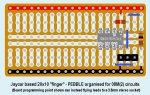
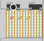
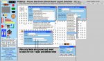
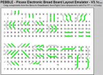
Personally, I use Pebble almost entirely for the design, layout and documenting of Veroboard prototypes, recently for "modules" that are very small (around 1 square inch). That has rather different requirements to the "Solderless Breadboard" application for which I believe Pebble was orginally intended. In particular, it's only just struck me that in general the component images for "stripboard" applications often have their pins/leads inside their outline, whilst breadboard applications usually have them outside, often by the addition of "wires".

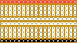
An example is the vertical electrolytic capacitors: For a (solderless) breadboard one will usually "spread" the leads to fit the required spacing (using the "size" regardless of the actual physical package dimensions) whilst with stripboard the leads will often be spaced around 0.1" (1.5 - 3.5 mm) and one chooses the size to "mask" the unavailable holes (say 4 - 10 mm diameter).

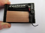
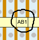
Another example is that I recently wanted to include a buzzer/sounder in my design and both already exist in Pebble, with attached "wires" which are probably perfectly adequate for a breadboard layout. But I wanted the 12mm diameter buzzer to occupy a reasonably accurate location on my Veroboard layout, and the 8mm spaced pins can be positioned in any of 8 (rotational) orientations (if one includes that the buzzers are polarised (with + / GND pins). The orientation differences may seem subtle, but are significant when you're fitting a 12mm diameter sounder onto a 14mm wide piece of veroboard. ;)

Actually, I don't find adding additional images difficult; I use an ancient version of "PaintShop Pro" but maybe others can suggest a more appropriate/modern application ? Often it's just a matter of rotating or cropping an existing image but I would prefer to put the modified image into a "spare" location, rather than overwrite an existing image. Generally, the "grid offset" is not a major issue, the images usually have a (pink) "transparent" colour, so one can see how the image "sits" on the grid and then add a small transparent "margin" on the appropriate side (at 26 pixels per 0.1" offset). It does make the active "cursor grab" area larger but is an acceptable workaround to having to edit Java files. ;)

In the past I have somtimes rejected a "drawing" package because it 
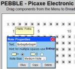
doesn't offer a "Lock to Grid" feature, but with Pebble I occasionally find it a hindrance. Apparently the individual images don't have a "lock to grid" attribute / flag, but might there be enough for a whole "group" like the "Note" symbols (if you hadn't noticed), or perhaps 
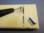
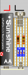
in the Notes group ? My particular candidates are the new "screws" (used to emulate AA battery terminals) and the LiFePO4 cells (also, I might re-scale the horizontal one so that it can "drop into" the normal alkaline "battery box" images).

So how do YOU use Pebble?

Cheers, Alan.
 

westaust55

Moderator
Hello sedeap,

I am currently working on some further minor Changes to PEBBLE.
When these are finished (soon) I will send you a file to provide some extra English/Spanish translations.

Suggest that you hold uploading a new version for a little longer.

Thanks
 

westaust55

Moderator
Hello folks,

attached is the latest update file. This includes all up edits and image file since V3.1 excluding the very large proto-board image file.
The one large image file is still available as partB in post 745 on previous page of this thread

I will next look to writing some notes on how to add ones own components and images.
Also to prepare a list of new text segments for Sedeap to help with a translation to Spanish.


EDIT:
Some more checking just when one thinks all is working and I note that the Load/Save function is "breaking"/failing where there are any of the 1-span wire links.
Worked for the "ProtoBoard" Group at 3.1c. A task to try and identify why tomorrow . . . . .


EDIT 2:
The V3.1d update file is removed here to avoid confusion. please see the next post
 
Last edited:

westaust55

Moderator
Hello folks,

the problem I spied yesterday had now (hopefully) been fixed.


Attached are the PEBBLE V3.1e update file(s) containing all new items since V3.1 dated 2011.

V3.1e also includes some 90 degree bends in the 1-Span wire link group for more routine flexibility.

PartA contains everything except the image for the new breadboard Datak 12-600B which is a large file.
PartB only has the image for the Datak 12-600B proto-typing board - so not essential if you do not want to use that board.
 

Attachments

westaust55

Moderator
Attached is a txt file with a series of text strings.

I am seeking assistance for conversions to Spanish, Czech and French.

Sedeap will provide the Spanish translations.

Any other forum members willing to assist with the Czech and French versions.

Thanks in advance
 

Attachments

westaust55

Moderator
Further to the information at post 734 on how to add a new breadboard or strip/protoboard into PEBBLE,

Attached is a first pass at how to add your own components to PEBBLE.
It is difficult to cover all eventualities or permutations on devices/packages, colours, sizes, orientations, etc in a few pages but hopefully there is sufficient information here to guide folks.

Again as mentioned in the document, ALWAYS make a BACKUP BEFORE starting any edits to the program files as I will not guarantee to fix your files if you cause a program failure.
You will not wipe you hard disk or damage hardware but it can be relatively easy just by omission of a brace symbol or inclusion of a space, etc. to cause problems.

I know that a few folks have successfully done some edits, typically to the existing images or extension to the Miscellaneous group (under the LDR icon).
For those brave souls who wish to have a try, let me know if some further (hopefully brief) explanation should be included.
 

Attachments

Top