For sale.Cold fusion reactor.Home made.Not working.$2000 ONO

John West

Senior Member
I've been soldering for 50 years or more, and I recently had a blood test done to see if they detected any lead in my system. The test came up negative. However, I tend to hold my breath as I'm soldering and the fumes rise into my face.

A small fan can be placed to draw the fumes away. Just don't point it at the work because then the moving air will cool down your iron's tip as well as the connection you wish to make. It takes a surprisingly small amount of air movement to make soldering more difficult.
 

120ThingsIn20Years

Senior Member
We haven't even finished up with resistance, Pete. :)

The one difference in the water tap analogy that is important for resistors is that as current flows through them, voltage is dropped by them. As the "volume" of current flows through them, the "pressure" (voltage) drops. The difference between the input voltage and the output voltage means that there is a specific voltage difference between the input and the output that has been "dropped" by the resistor. Where did it go? It went into heat.

A resistor dissipates heat as it drops voltage, sometimes a little, sometimes a lot. The amount dissipated can be known by applying this formula: P=IR. That's Power (P) dissipated by the resistor equals current (I) times Resistance (R).

And no, I don't know why the letter "I" is used to represent current. Just a tradition, I guess. Perhaps someone else here knows. But by applying this formula you can calculate just how much heat will be dissipated (in Watts) by a given resistor at a given voltage or current.

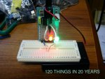
That's important, because an incorrectly sized resistor can get too hot and start a fire, or pop like a fuse but in a much messier manner.

The other equation necessary for working with resistors is E=IR. That's E (for electromotive force {we call it voltage}) equals I (current) times R (resistance.) With this equation and knowing the values of any 2 of the variables you can calculate the third value. You will find many online calculators that will calculate these voltages, currents, resistances and power for you if you simply plug in the values you have. Just do a web search for "Ohm's Law calculator," or if you're handy with math just grab a pocket calculator and do it yourself.

Sorry if this sounds too inane. It's very difficult to know in the forum just what a poster already understands and what they don't, so I usually try to keep everything as simple as I can. It doesn't hurt those with a deeper knowledge, and it helps those who are looking at something totally foreign to them.
Please just keep it coming.

Every time I think I have a grasp on something I suddenly find some new stuff from all you (you the people and you John West) people's input.

But...

this post now has me even more confused.

If a resistor dumps excess energy as heat, doesn't that mean it's acting more like a leak than a tap?

Venting some potential into the ether.

I think I can re-ask my original question better this way.

If I have a circuit...

+
resistor
light bulb
-

will that use less battery than

+
light bulb
-

?
 

120ThingsIn20Years

Senior Member
Everyone on this board seems to have breathed a lot of solder fumes over their lives, and not meaning to belittle any other groups of people, there seems to be quite a few of you kicking about with a stack of excess brain cells that still seem to be firing quite nicely.

I'm starting to wonder if I should give my mum a hard time for not exposing me to enough lead fumes as I was growing up. It seems to have worked well for all you people :)
 

120ThingsIn20Years

Senior Member
I'm planning a post for my blog on coding.

It will be one of only two posts on coding because the majority of my readers wont want to sit through it, but I thought I'd do one on the reuse of code segments, and perhaps one on "if then".

I feel that pretty much raps up coding for anyone who has had no exposure to it. ie that demonstrates the potential and gives a general feeling of how a computer does what it does.

Generally on my blog, I'm trying to generate a "have a go, you wont regret it" kind of flavour. I'm looking at trying to interest an audience to have a bit more of a look in a general direction rather than actually pass on everything I learn from you people (or from everyone on all the other topic specific forums).

With that in mind I thought I'd perhaps post some code that works it's way through a simple linear version evolving into something that shows a glimpse of the potential that reuse of code has to offer.

Just keep in mind this stuff really has to be simple. Most of my readers wont actually do this stuff, so I'm not writing for someone like me who is totally obsessed with gaining new knowledge, I'm writing for someone who might want to take up perhaps one of two of the 120 things I intend to expose them to, and wander over to the PICAXE forum and perhaps get hooked.

So ...

With all that in mind this post might be a very dull read to most of the people following this thread, because my code is not only PICAXE beginner's code, but it's also designed to be viewed by people who know even less than me. (at this point I should mention that I have done a bit of VB6 in the past, and a tiny bit of .net)

What I would like from anyone willing to give me some input, is suggestions for the next step in "maximising" this simple code. ie is there a next step to save a few bytes or condense it any further.

I have 4 versions of the same program and I cant see any more steps to illustrate reuse of code or making it more efficient, so if you are willing, can you have a look and give me any pointers, or point out any wacky stuff I've done.

You could probably just skip to the last one to point out any improvements to be made.

This stuff is a few different versions of a simple program that flashes an SOS via a LED connected to pin 1 on a 08m chip (I think :) ) and starts with a linear program like you might have created in your first ever program, and progresses through to as far as my skills allow. Ill just drop them in one after the other with no further explanation. They wont fit on this forum, so I'll drop it into the next post, so read on or skip ahead to the next post and forget this entire segment of this thread as desired :).
 

120ThingsIn20Years

Senior Member
Code:
 '-----------------------------------------------'By 120ThingsIn20Years
'2011-09-06
'No rights reserved 


'The evolution of some code for demonstration purposes on my blog


'SOS flasher 


'ver 1 - all code is a continous progression and is processed in order 
' like reading a book


'Uses chip PICAXE 08M 
'Memory use = 75 bytes of 256
'-----------------------------------------------


main: 'The program starts here


    'B.1 is an output pin on the PICAXE chip
    'High means the pin has power going to it
    'Low means the pin doesnt have power going to it
    'The red light is connected to this pin B.1 so if there is power
    ' going to it (high B.1) it's on, and if there is no power going 
    ' to it (low B.1) it's off.
    
    
    ' Create a Morse code letter "S" by flashing the light 3 short flashes
    
        high B.1     'switch on output pin 1
        pause 200     'wait 1/5th of a second (2000 = 1 second)
        low B.1     'switch off output pin 1
        pause 200     'wait 1/5th of a second
        high B.1     'switch on output pin 1
        pause 200     'wait 1/5th of a second
        low B.1     'switch off output pin 1
        pause 200    'wait 1/5th of a second
        high B.1     'sswitch on output pin 1
        pause 200     'wait 1/5th of a second
        low B.1     'switch off output pin 1
        pause 200
        
    Pause 600    'pause for the extra time to indicate the end of a letter
        
    
    'Create a morse code letter "O" flashing the light 3 long flashes
    
    high B.1 
        pause 600     ' pause approximately 2/3rd of a second for long flashes
        low B.1     
        pause 200
        high B.1     
        pause 600 
        low B.1    
        pause 200
        high B.1 
        pause 600 
        low B.1 
        pause 200
        
    Pause 600    'pause for the extra time to indicate the end of a letter
        
    
    ' Create a Morse code letter "S" again by flashing the light 3 short flashes
    
        high B.1     
        pause 200     
        low B.1     
        pause 200     
        high B.1     
        pause 200     
        low B.1     
        pause 200    
        high B.1     
        pause 200     
        low B.1 
        pause 200
        
    Pause 600    'pause for the extra time to indicate the end of a letter
        
    Pause 1400    'then pause for the extra time to indicate the end of a word


goto main ; loop back to the start and run it again

Code:
'-----------------------------------------------'By 120ThingsIn20Years
'2011-09-06
'No rights reserved 


'The evolution of some code for demonstration purposes for my blog


'Emergency hiker SOS flasher 


'ver 2 - all code is a continous progression but some values have been condenced to variables 


'Uses chip PICAXE 08M 
'Memory use = 75 bytes of 256
'-----------------------------------------------


main: 'The program starts here


'Morse code uses...
    '1 unit of duration for a "Duration" (the space between the dots and dashes, and also for a dot)
    '3 units of duration for a Dash and for the gap between letters
    '7 units of duration for the gap between words
    
    'so here we store the length of a standard duration, so if we need to speed up 
    ' the flashing, it can all be adjusted from the one spot.


symbol StandardDuration = 200        'Set the value of the standard unit eg.a dot
                        'and the space between dots and dasheses
                        'changing this value would change the typing 
                        'speed of the flashes over the entire program
                        
symbol DashAndLetterGap = StandardDuration * 3     'set the DashAndLetterGap to 3 times the 
                        'length of the StandardDuration
                    
symbol WordGap = StandardDuration * 4    'Set the length of the word gap to
                            '4 times the length of the 
                            'standard Duration (should be 3.5, but I
                            'cant do decimals yet)
                            
    
    ' Create a Morse code letter "S" by flashing the light 3 short flashes
    
        high B.1             'switch on output pin 1
        pause StandardDuration     'wait 1/5th of a second 
        low B.1             'switch off output pin 1
        pause StandardDuration     'wait 1/5th of a second
        high B.1             'switch on output pin 1
        pause StandardDuration     'wait 1/5th of a second
        low B.1             'switch off output pin 1
        pause StandardDuration    'wait 1/5th of a second
        high B.1             'sswitch on output pin 1
        pause StandardDuration     'wait 1/5th of a second
        low B.1             'switch off output pin 1
        pause StandardDuration
        
    Pause DashAndLetterGap    'pause for the extra time to indicate the end of a letter
        
    
    'Create a morse code letter "O" flashing the light 3 long flashes
    
    high B.1 
        pause DashAndLetterGap     ' pause 2/3rd of a second for long flashes (dash)
        low B.1     
        pause StandardDuration     'pause for 1/5 of a second between dashes
        high B.1     
        pause DashAndLetterGap 
        low B.1    
        pause StandardDuration
        high B.1 
        pause DashAndLetterGap 
        low B.1 
        pause StandardDuration
        
    Pause DashAndLetterGap    'pause for the extra time to indicate the end of a letter
        
    
    ' Create a Morse code letter "S" again by flashing the light 3 short flashes
    
        high B.1     
        pause StandardDuration     
        low B.1     
        pause StandardDuration     
        high B.1     
        pause StandardDuration     
        low B.1     
        pause StandardDuration    
        high B.1     
        pause StandardDuration     
        low B.1 
        pause StandardDuration
        
    Pause DashAndLetterGap    'pause for the extra time to indicate the end of a letter
        
    Pause WordGap    'then pause for the extra time to indicate the end of a word


goto main ; loop back to the start and run it again

Code:
'-----------------------------------------------'By 120ThingsIn20Years
'2011-09-06
'No rights reserved 


'The evolution of some code for demonstration purposes 


'Emergency hiker SOS flasher 


'ver 3 - code calls on an "S" and an "O", and repeats
'Uses chip PICAXE 08M 
'Memory use = 68 bytes of 256
'-----------------------------------------------


main: 'The program starts here


'In this version we create an "S" and an "O" that we can call up as required


symbol StandardDuration = 200        'Set the value of the standard unit eg.a dot
                        'and the space between dots and dashes
                        'changing this value would change the typing 
                        'speed of the flashes over the entire program
                        
symbol DashAndLetterGap = StandardDuration * 3     'set the DashAndLetterGap to 3 times the 
                        'length of the StandardDuration
                    
symbol WordGap = StandardDuration * 4    'Set the length of the word gap to
                            '4 times the length of the 
                            'standard Duration (should be 3.5, but I
                            'cant do decimals yet)


CreateSOS:


     gosub MorseS
     gosub MorseO
     gosub MorseS
     
     pause WordGap
     
 GOTO CreateSOS


end


    ' Create a Morse code letter "S" by flashing the light 3 short flashes
    MorseS:
    
        high B.1             'switch on output pin 1
        pause StandardDuration     'wait 1/5th of a second 
        low B.1             'switch off output pin 1
        pause StandardDuration     'wait 1/5th of a second
        high B.1             'switch on output pin 1
        pause StandardDuration     'wait 1/5th of a second
        low B.1             'switch off output pin 1
        pause StandardDuration    'wait 1/5th of a second
        high B.1             'sswitch on output pin 1
        pause StandardDuration     'wait 1/5th of a second
        low B.1             'switch off output pin 1
        pause StandardDuration
        
    Pause DashAndLetterGap    'pause for the extra time to indicate the end of a letter
        
    return
    
    
    'Create a morse code letter "O" flashing the light 3 long flashes
    MorseO:
    
        high B.1 
        pause DashAndLetterGap     ' pause 2/3rd of a second for long flashes (dash)
        low B.1     
        pause StandardDuration     'pause for 1/5 of a second between dashes
        high B.1     
        pause DashAndLetterGap 
        low B.1    
        pause StandardDuration
        high B.1 
        pause DashAndLetterGap 
        low B.1 
        pause StandardDuration
        
    Pause DashAndLetterGap    'pause for the extra time to indicate the end of a letter
    
    return
and the final version wont fit here so please skip to the next post...
 

120ThingsIn20Years

Senior Member
Code:
'-----------------------------------------------
'By 120ThingsIn20Years
'2011-09-06
'No rights reserved 


'The evolution of some code for demonstration purposes 


'Emergency hiker SOS flasher 


'ver 4 - code calls on an "S" and an "O", which in turn call dots
        ' and dashes,and then repeats
        
'Uses chip PICAXE 08M 
'Memory use = 66 bytes of 256
'-----------------------------------------------


main: 'The program starts here


'In this version we see the creattion of things that become Dots or dashes, and we now
'create our letters out of them


symbol StandardDuration = 200        'Set the value of the standard unit eg.a dot
                        'and the space between dots and dashes
                        'changing this value would change the typing 
                        'speed of the flashes over the entire program
                        
symbol DashAndLetterGap = StandardDuration * 3     'set the DashAndLetterGap to 3 times the 
                        'length of the StandardDuration
                    
symbol WordGap = StandardDuration * 4    'Set the length of the word gap to
                            '4 times the length of the 
                            'standard Duration (should be 3.5, but I
                            'cant do decimals yet)


CreateSOS:


     gosub MorseS
     gosub MorseO
     gosub MorseS
     
     pause WordGap
     
 GOTO CreateSOS


end


'---------------------------------------------------------------------


    ' Create a Morse code letter "S" by flashing the light 3 short flashes
    MorseS:
    
        gosub dot
        gosub dot
        gosub dot
        
    Pause DashAndLetterGap    'pause for the extra time to indicate the end of a letter
        
    return
    
    
    'Create a morse code letter "O" flashing the light 3 long flashes
    MorseO:
    
        gosub dash
        gosub dash
        gosub dash
        
    Pause DashAndLetterGap    'pause for the extra time to indicate the end of a letter
    
    return
        
'------------------------------------------------------
    
    Dot:    'Create a Dot
            
        high B.1     
        pause StandardDuration      
        low B.1             
        pause StandardDuration
        
    return
            
            
    Dash:    'Create a dash
        
        high B.1 
        pause DashAndLetterGap 
        low B.1 
        pause StandardDuration
            
        
    return
 
Last edited:

moxhamj

New Member
@John West
The one difference in the water tap analogy that is important for resistors is that as current flows through them, voltage is dropped by them. As the "volume" of current flows through them, the "pressure" (voltage) drops. The difference between the input voltage and the output voltage means that there is a specific voltage difference between the input and the output that has been "dropped" by the resistor. Where did it go? It went into heat.
This has me thinking, if energy is lost as heat in a resistor, what happens in a tap? I think the answer is exactly the same - energy is lost as heat as well. The heat ends up in the water. Normally you wouldn't notice the slight temperature rise but I have seen it in a very dramatic form with a pump that got an airlock and so the water went round and round through the small gaps inside the pump and eventually boiled (I burnt my hand on the case).

A tap is very much like a resistor. You can even set up a tap as a variable load on a pump to check the maximum efficiency point (or at least check that the graphs that came with the pump are correct).

Current is water flow and in a circuit you can't remove any water from the circuit so it is not like a leaking pipe. The current must go around and around. (same as electrons don't leak out of a wire).

Nice soldering BTW!
 

120ThingsIn20Years

Senior Member
@John West

This has me thinking, if energy is lost as heat in a resistor, what happens in a tap? I think the answer is exactly the same - energy is lost as heat as well. The heat ends up in the water. Normally you wouldn't notice the slight temperature rise but I have seen it in a very dramatic form with a pump that got an airlock and so the water went round and round through the small gaps inside the pump and eventually boiled (I burnt my hand on the case).

A tap is very much like a resistor. You can even set up a tap as a variable load on a pump to check the maximum efficiency point (or at least check that the graphs that came with the pump are correct).

Current is water flow and in a circuit you can't remove any water from the circuit so it is not like a leaking pipe. The current must go around and around. (same as electrons don't leak out of a wire).

Nice soldering BTW!
Re: soldering. I was surprised to see that even I could tell the difference between my iron and pete's.

Normally with things like that it takes some knowledge before you can tell.
To anyone who's never used a drill, the $20 one is just as good as the $800 one.

But Pete's iron was sooooo much better.
 

120ThingsIn20Years

Senior Member
Please see:
http://www.kpsec.freeuk.com/faq.htm

And,
there are many answers to potential questions there
as well.

e
even this from that link...

[h=4]What component has a black stripe in the centre (it looks like a diode)?[/h]A small component about the size of a resistor or signal diode with a single black stripe in the centre is a zero-ohm resistor, it is really just a wire link! These components are used on commercial PCBs because they are easier for machines to handle than small pieces of wire. The single black stripe is logical because it means zero in the resistor colour code. Ordinary resistors have at least four stripes. Diodes have a single stripe near one end, not in the centre.
Further information: Diodes | Resistors
 

120ThingsIn20Years

Senior Member
@John West

This has me thinking, if energy is lost as heat in a resistor, what happens in a tap? I think the answer is exactly the same - energy is lost as heat as well. The heat ends up in the water. Normally you wouldn't notice the slight temperature rise but I have seen it in a very dramatic form with a pump that got an airlock and so the water went round and round through the small gaps inside the pump and eventually boiled (I burnt my hand on the case).

A tap is very much like a resistor. You can even set up a tap as a variable load on a pump to check the maximum efficiency point (or at least check that the graphs that came with the pump are correct).

Current is water flow and in a circuit you can't remove any water from the circuit so it is not like a leaking pipe. The current must go around and around. (same as electrons don't leak out of a wire).

Nice soldering BTW!
There would be a little extra friction at a tap restricting, but I would have thought that there wouldn't be a loss in pressure. I think perhaps flow is converted to pressure. When I restrict the flow of a hose with my thumb, I can throw water further.

I still dont understand resistors.

does a resistor eat battery capacity?

From what I can gather trying to make some meaning out of the circuit diagrams I'm looking at, there seems to almost always be a different path and the resistor tends to be bleeding off some power from say a power rail on a breadboard, and taking it where some lessor voltage is required. So I cant tell if its burning energy to reduce the voltage on the other side, of the flow is just hanging back on the power rail waiting to do something else.

In a hydro electric dam, you tun the tap off a bit at the generator, and you are saving some water/power for later, but you could also diver some water out to sea at a junction just before the generator, and you would get the same result, less output, but you would be wasting some water/power that you couldn't use later.


It turns out its possible to be excitedly confused :)

Who knew :)
 

moxhamj

New Member
I like the way you are thinking and asking the hard questions. I've had to think a bit about that last one!

Ok, voltage is pressure.

Current is flow rate in litres per second.

The velocity of the water doesn't really have an analogy for the resistor. So you put your finger over the pipe and the velocity goes up but that doesn't mean anything, what is important is that the flow rate goes down. The more you put your finger on the pipe, the higher a resistor you are creating, the less litres per second flow, right to the point where you have a very high resistance and there is no flow at all.

Also, while you might be squirting your hosepipe in the air, there is not really an 'outside world' like that in a circuit. Everything runs in a closed loop. The water starts at the top of the hill with a high voltage and no flow. You turn on a switch (open a valve at the top) and the water flows. It might flow through a resistor which could be a narrow pipe. (every wire is a resistor but usually a very low value one, like 0.01 ohms). Then your flow might go through a variable resistor, like a tap. Then it might go into something that does something useful, like a turbine (eg a motor). Then it ends up at the bottom of the hill. But you can't get rid of the water, and it still has to flow in a loop. Think of a battery as a self contained device that transports the water from the bottom back to the top of the hill.

Motors and lightbulbs are interesting because they change their resistance.

Turn on a lightbulb and it has a very low resistance so lots of current flows. As it heats up and emits light the resistance rises until a predetermined current flows.

Turn on a motor and it also has a very low resistance but this rises as the motor speeds up. This creates a back EMF, or voltage, that under no load conditions ends up being the same as the volts going in. Spin a 3V motor fast enough and it will generate 3V.

Oh, and two formulas already mentioned before.
V=IR where V is volts, I is current in amps, and R is resistance in ohms
W=IV where W is watts, I is current in amps and V is volts

Put 1V across a 1ohm resistor and 1 amp will flow.
How much heat will it produce?

1V x 1A = 1 watt.


Keep the questions coming!
 

120ThingsIn20Years

Senior Member
I like the way you are thinking and asking the hard questions. I've had to think a bit about that last one!

Ok, voltage is pressure.

Current is flow rate in litres per second.

The velocity of the water doesn't really have an analogy for the resistor. So you put your finger over the pipe and the velocity goes up but that doesn't mean anything, what is important is that the flow rate goes down. The more you put your finger on the pipe, the higher a resistor you are creating, the less litres per second flow, right to the point where you have a very high resistance and there is no flow at all.

Also, while you might be squirting your hosepipe in the air, there is not really an 'outside world' like that in a circuit. Everything runs in a closed loop. The water starts at the top of the hill with a high voltage and no flow. You turn on a switch (open a valve at the top) and the water flows. It might flow through a resistor which could be a narrow pipe. (every wire is a resistor but usually a very low value one, like 0.01 ohms). Then your flow might go through a variable resistor, like a tap. Then it might go into something that does something useful, like a turbine (eg a motor). Then it ends up at the bottom of the hill. But you can't get rid of the water, and it still has to flow in a loop. Think of a battery as a self contained device that transports the water from the bottom back to the top of the hill.

Motors and lightbulbs are interesting because they change their resistance.

Turn on a lightbulb and it has a very low resistance so lots of current flows. As it heats up and emits light the resistance rises until a predetermined current flows.

Turn on a motor and it also has a very low resistance but this rises as the motor speeds up. This creates a back EMF, or voltage, that under no load conditions ends up being the same as the volts going in. Spin a 3V motor fast enough and it will generate 3V.

Oh, and two formulas already mentioned before.
V=IR where V is volts, I is current in amps, and R is resistance in ohms
W=IV where W is watts, I is current in amps and V is volts

Put 1V across a 1ohm resistor and 1 amp will flow.
How much heat will it produce?

1V x 1A = 1 watt.


Keep the questions coming!
Perhaps I've used up my quota of think for the day.

I understand all the words :)

I think some answers need to be stuck to the back of the toilet door for a bit to sink in :)

So a battery would be more like a pump within this water world.

And ac would be like a pump rocking back and forwards.

But this pressure business makes volts and amps the same thing....

what happens to amps after a resistor?

I dont think amps really means anything to me. I thought it did.

I think it's time to play with the metre.

To measure amps I need to put the MM into the circuit. In series I guess. Right?

I cant see what's getting consumed here. Why does a battery go flat if the electrons are finding their way back. Do they just find there way back to only a sectioned off bit of a battery, or is there really a circuit, ie a loop?
 

moxhamj

New Member
I cant see what's getting consumed here. Why does a battery go flat if the electrons are finding their way back. Do they just find there way back to only a sectioned off bit of a battery, or is there really a circuit, ie a loop?
The battery is converting chemical energy to electrical energy. It's job is to push the electrons round the circuit. When the battery goes flat it has run out of chemical energy and runs out of push. The volts get less and less and it can't supply as many amps. Your lightbulb in your circuit gets dim and then goes out.

And yes, there really has to be a complete circuit - you can't leave electrons with no-where to go.

(well, ok. yes you can cause them to take flight, as happens in a thermionic valve, or a cathode ray tube TV. But that doesn't apply for these sorts of electronic circuits. And yes, inside the battery charge can be transported with ions rather than electrons.)

In a lot of cases though, you don't have to worry initially about the theory. In some ways it is better to jump in and follow an electronics 'recipe', and then later on go back and try to understand the theory.

Electrical circuits http://en.wikipedia.org/wiki/Electrical_network

The formal explanation of currents and volts are on this page - Kirchhoff's current and voltage laws. The current law is the same as the water flow - current can't 'disappear' in a circuit - it has to go round and round. If current goes into a node (ie a component) it must come out again. You can have current coming in from several places (eg via several wires or resistors) and going out by several routes but the sum of the inputs must equal the sum of the outputs.

The practical use of this law is that if you have a current meter measuring amps, it does not matter where you put it in the circuit. You can put it between the +ve of the battery and your lightbulb. Or between the other connection on the lightbulb and the negative of the battery but the amps will always be the same.
 
Last edited:

hippy

Technical Support
Staff member
Don't get too hung up on water = electricity as it's not a perfect analogy for all things, just explains some basic principles.

Another way to visualise things is a battery as a massive barracks of tiny men who play the role of electrons and love running down corridors. Consider a circuit of wires and resistors like a labyrinth of corridors; as soon as connected the little chaps rush out, flood down the corridors, back to the battery, and then around again.

How wide the corridors are ( resistance ) determines the rate of flow of our men ( current ). Have a wide corridor ( low resistance ) and then a narrow corridor ( high resistance ) and throughput is limited to the rate they can get down the narrow corridor, put two corridors in parallel and they'll divide down each and more come out the other end at a faster rate ( higher current ).

If you don't connect the corridors back to the battery they may be full of our electron-men waiting to move onwards but they will all have come to a standstill, so zero flow of men ( zero current ).

The battery goes flat because the men eventually get exhausted with all this running around and take to their beds and there's a diminishing supply coming out of the barracks to run round again. How quickly they tire depends on how often they are running around the corridors; build a wide corridor loop and you'll have large numbers running round quickly ( low resistance, high current ) and they'll soon tire, with a narrow corridor loop they'll move round more slowly ( higher resistance, lower current ) and last longer.
 

SAborn

Senior Member
You've heard the expression "There's not enough juice in that battery to start my car/light my torch/etc...." so it seems simple to me - batteries go flat when the juice runs out.
You are not using lemon batteries again are you.;)

Just wonder if you used a sun dried lemon... would that make a dry cell battery??
 

SAborn

Senior Member
Hippy,

I like you explanation, im just glad you didnt use a ship for you battery, as then the men would have been called "sea men", now read your explantion with the term sea men in placement of men and it tells a completely different story.
 

120ThingsIn20Years

Senior Member
Did anyone miss me?

I've been busy.

It took around 3 hours, but I did this to my little kit. :)

120 Things in 20 years - 120 things in 20 years - Electronics - PICAXE with breadboard.jpg

In case nobody can work out what I'm so excited about...

I successfully removed a red LED and a 330 ohm resistor with my new solder sucker
I remounted them back on the board with a jumper so I can isolate them
I found and fixed the poor joint I made that gave an intermittent fault
I added a row of 90 deg header pins (I think that's what they are) and connected pin 1 and pin 2 via wires so I could plug it into a bread board.
I recreated the original flashing LED on the breadboard to test
And I added a plug to the power in holes rather than having the wires from the battery pack soldered

Yay me!

I wish there was an icon that better described the grin on my head after I found my fault and it all worked :)
 

jtcurneal

Senior Member
Don't get too hung up on water = electricity as it's not a perfect analogy for all things, just explains some basic principles.
I have tried to teach hundreds of students of all ages enough electrical knowledge to pass Ham Radio license tests over the years.
I usually used a water analogy to help some of them learn about Ohms Law.
If they thought of water pressure as voltage, Water flow as current and a leaky faucet valve as a variable resistor.
As the faucet valve is opened ( the resistance is lowered ) the water flow ( the current ) increases.
As the faucet valve is closed ( the resistance is increased ) the water flow ( the current ) decreases
With a constant pressure ( voltage ) the water flow ( current ) is determined by the valve opening ( the resistance ).
With a constant valve opening ( resistance ), the water flow ( current ) will change with changing water pressure.
As anyone that has lived in a home with limited water pressure knows, if you open several valves at the same time,
the water flow ( current ) from each faucet will be reduced as the water pressure ( voltage ) drops,
like a battery that is running out of juice.

This analogy seemed to help most students understand a bit about electricity and electronics.

Joel
 

SAborn

Senior Member
I wish there was an icon that better described the grin on my head after I found my fault and it all worked
Well done!! from the look of things some of the bits and pieces i gave you has already come in handy.
Although 3 hours for 2 leds and a half dozen headers make me think you will not be retiring soon on the profits from circuit building.

It is a good feeling when your first attempt at a project all works, i still remember my first flashing led with a picaxe and the smile.

Lookout Bill Gates 120thingstodo is here.................

Pete.
 

lbenson

Senior Member
Excellant progress.

To me, in the water analogy, the negative/0V terminal of the battery is equivalent to sea level--no more useful work to be done with the water unless it again is elevated.

Your image is very clear, but larger than it needs to be. 640x480 is good for many purposes, and better for forum users who have slower connections. Here it is at 1/5th the size (56KB vs 277KB), and no loss of useful clarity (IMHO).
 

Attachments

moxhamj

New Member
I wish there was an icon that better described the grin on my head after I found my fault and it all worked
Great work!

What is next - writing a program to flash that led in more complicated ways? Are you ready to try a servo?
 

boriz

Senior Member
Congratulations and welcome to the club. That grin and the associated feeling of satisfaction is the light at the end of the tunnel, and it's always there waiting. It's the reason I play electronics :)

Like Hannibal said. "I love it when a plan comes together."
 

120ThingsIn20Years

Senior Member
Well done!! from the look of things some of the bits and pieces i gave you has already come in handy.
Although 3 hours for 2 leds and a half dozen headers make me think you will not be retiring soon on the profits from circuit building.

It is a good feeling when your first attempt at a project all works, i still remember my first flashing led with a picaxe and the smile.

Lookout Bill Gates 120thingstodo is here.................

Pete.
Or I could just start my own shop with the sack full of components you gave me.

Speaking of witch, would that silicon spray be useful on my laptop keyboard full of coffee?
 

120ThingsIn20Years

Senior Member
Excellant progress.

To me, in the water analogy, the negative/0V terminal of the battery is equivalent to sea level--no more useful work to be done with the water unless it again is elevated.

Your image is very clear, but larger than it needs to be. 640x480 is good for many purposes, and better for forum users who have slower connections. Here it is at 1/5th the size (56KB vs 277KB), and no loss of useful clarity (IMHO).
point taken
 

SAborn

Senior Member
NO, dont use silicon spray on the keyboard.

I dont know why you gave the keboard coffee in the first place, it not good for them, mine just eat dust.
 

120ThingsIn20Years

Senior Member
Great work!

What is next - writing a program to flash that led in more complicated ways? Are you ready to try a servo?
I got the LED tapping out an SOS in morse code to get a feel for the language and it feels pretty familiar. I'm not sure if I'm using things correctly, but the code side of things probably wont be a problem for me, which is nice because that's one less thing to worry about.

There seems to be a lot in common between a circuit and a program.

I have a thermal resistor and a light based one... hang on, I should start looking things up when I don't know what they are called...

a thermistor and a photoresistor so I might try something with analogue input.

I was going to make a LED fade up and down but from what I can understand, I'm not going to be able to do that yet.

Although Now that I think of it, I had the thing flashing really fast at one stage and it looked like it was solid on, so I should be able to do it with timing.

start
a=a+1
B.1 high
pause a
B.1 low
back to start

then limit "a" then go backwards.

I'll try it.
 

120ThingsIn20Years

Senior Member
NO, dont use silicon spray on the keyboard.

I dont know why you gave the keboard coffee in the first place, it not good for them, mine just eat dust.
I have a magic cardboard box that I've been keeping for years for old keyboards. You put broken ones in at the back, stock rotation style, and take one from the front that used to be broken, and it works again. I think it has something living in the back of the box that lives on beard hair, dust and coffee :)
 

120ThingsIn20Years

Senior Member
My LED fader on the 08M

Yay me!

It could be a bit smoother. Can I use a capacitor to make that happen? How do you bleed power from a capacitor slowly?

Code:
'written by 120ThingsIn20Years
'no rights reserved
'2011-09-07
'PICAXE 08M with a 330ohm resistor and an LED on pin 2

'-----------------------------------------------------------------------------

symbol UberTime = 7                'sets total number of cycles in a fade


symbol Calmness = 10               'sets the pause at each level of fade
symbol CalmnessCounter = b3    'used in the Calmness for next sub-loop


symbol counter = b1                 'used in for next loops


symbol CountDown = b2            'because I cant use a negive number in a 
                                                'for next to count down
symbol MaxLowTime = 12          'sets the off time of the LED I was going to make
                                               ' this dynamic to give me greater resolution befor
                                               ' the LED flicker kicked in but got bored

main:

    'call the fades
    gosub FadeUp
    gosub FadeDown


    goto main


end                    'not used

'-----------------------------------

FadeUp:

    for counter = 1 to UberTime                     'main fade up loop
        for CalmnessCounter = 1 to Calmness    'sub-loop to calm it all down and rest at each fade
            high b.2
            pause Counter                                'increase on length each pass
            low b.2
            pause maxlowtime                           'sets how long the LED is off
        next CalmnessCounter
    next counter
    
    return


FadeDown:


countdown = counter                                'grab the current value of lights on duration
                                                             'before it gets wiped by the new loop
    
    for counter = 1 to UberTime                   'main fade down loop
        countdown = countdown - 1               'sets length of on duration
        for CalmnessCounter = 1 to Calmness   'sub-loop to calm it all down and rest at each fade
            high b.2
            pause countdown
            low b.2
            pause maxlowtime                         'sets how long the LED is off
            if countdown = 1 then return           'premature return at end of cycle
            endif
        next CalmnessCounter
    next counter
    
    return                        'not used
 

John West

Senior Member
Attach a high value resistor from one end of the capacitor to the other to slowly discharge an LED after power is removed and the LED is running on the cap alone. The higher the resistance, the slower the fade. The rate depends on the values of both the capacitor and the resistor, (and the wattage of the LED.) Do a web search on the expression "capacitive time constant" for the explanation and the math to compute the resistor/capacitor discharge rate. It's pretty easy arithmetic.

To smooth out the pulsing of an LED that you wish to dim, either pulse at a very high rate and control the duty-cycle (percentage of time on vs time of for each pulse,) pulsing fast enough so you can see no flickering, or add a capacitor across the LED to smooth out the ripple caused by the pulsing. The larger the value of capacitor, the smoother the LED light at a given frequency. Also, the higher the frequency, the smoother the light for a given capacitance.
 
Last edited:

SAborn

Senior Member
John,

At this stage i think the largest cap he has handy would be 10uF that i gave him a few of, and not much in the way of a resistor selection with 10K or 22K being the highest.

When dollars permit he will add to his component stock.
Just to give an idea of what he has to work with.

Pete.
 

120ThingsIn20Years

Senior Member
Attach a high value resistor from one end of the capacitor to the other to slowly discharge an LED after power is removed and the LED is running on the cap alone. The higher the resistance, the slower the fade. The rate depends on the values of both the capacitor and the resistor, (and the wattage of the LED.) Do a web search on the expression "capacitive time constant" for the explanation and the math to compute the resistor/capacitor discharge rate. It's pretty easy arithmetic.


To smooth out the pulsing of an LED that you wish to dim, either pulse at a very high rate and control the duty-cycle (percentage of time on vs time of for each pulse,) pulsing fast enough so you can see no flickering, or add a capacitor across the LED to smooth out the ripple caused by the pulsing. The larger the value of capacitor, the smoother the LED light at a given frequency. Also, the higher the frequency, the smoother the light for a given capacitance.
controlling the duty cycle is what I think I did in the code in the previous post, leaving the LED off for "pause 10" and increasing the LED on time by 1 for with each loop.

I have 1000uf 25v capacitor.

25v would be its maximum rating right? So I could use that?
 
Last edited:

SAborn

Senior Member
Yes the 25v is the max rating and yes you can use that, although you might need to stack a few resistors in series.

A better way is to use PWM on one side of the led (say ground) and switch the led on and off via a second pin, although if you are using more than 1 led then the PWM side will need a transistor to supply the current needed for multiple leds.

This is a common technique used to fade in different colours when using a RGB led. (search the forum for fading RGB leds as its been covered many times)

Pete.
 

SAborn

Senior Member
Talk about cold fusion, this thread has become an iceberg.

It must be the OP is busy sorting the bags of junk i gave him or over mystified by the flashing leds.

For all the enthusiasm to get a board together its rather quite here to follow.

No this thread has not gone off line or moved to a different forum, and would seem as the reactor has stopped reacting.

Hence the jumpstart.............|_|-|_|-|......................................|-|.................?

Pete.
 

120ThingsIn20Years

Senior Member
I've just got my head down trying to learn without bugging everyone with questions I should be able to find on my own. The questions I cant work out will be back I can assure you :)

I've been flat on my back sick for a few days so I've really only been reading.

One thing that's got me baffled is the pin designations b.1, c.1. The manual is a little lacking in this regard.

Actually in quite a few places the manuals presume quite a bit of knowledge on the part of the reader. It's common practice to have a brief description of an acronym the first time you use it a text, but not so much in these manuals.


Manual 1 page 71 from memory, (I cant seem to open them last time I looked as the links were down due to the new site's normal teething process no doubt) has a description that relates to a previous naming convention, and doesn't really tell the newcomer much at all.

I cant for the life of me figure out why I'm using b.1 c.1 or b1 or any of the other methods of referring to pins and variables.

I'm sure I'll figure it all out eventually, but like I said I'm studying electronics now, trying to figure out how to interface with these things.

Once I get out of bed, I think my next step will be to make each of the circuits in the third manual on plug in boards like little shields so I can reuse them as I try more complex things. So basically make my own modular version of the experimenter kit. If I keep it all modular, I'll learn some stuff, get lots of soldering practice on nice cheep header pins, and get a collection of things to build up a better understanding of the coding side of things.

It will also be nice to know that if something is wrong with a circuit, it probably has nothing to do with my little plug in boards that I know actually work.

So, the current plan is...

---------------------------------

get better
make each of the interface circuits in the manual
learn some code for each of the circuits
start bugging you people again for more information
global domination via electronics based empire

---------------------------

in roughly that order

:)
 

SAborn

Senior Member
I am guessing you have not worked out ALL the manuals are on your computer already in Programming Editor, under the Help tab, there is no need to read them off the web site.
 
Top