For sale.Cold fusion reactor.Home made.Not working.$2000 ONO

120ThingsIn20Years

Senior Member
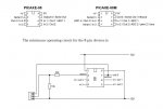
I thought I'd have a look at the circuit in between soldering attempts, and discovered I understand slightly less than I thought I did.

I didn't that that was possible, but you learn something new every day. :)

Or not.

I cant figure out what my R1 does.

The right hand side of it just seems to be at a dead end.

I thought I'd try to build it on my little breadboard I bought today to follow the flow and see not just where to put the components, but also see how they interacted with the other components.

So for example the capacitor seems to short circuit straight between the red and black wires.So I did some reading, and from what I can gather I think the capacitor might be used like that to smooth out noise prom the power supply. I cant see why there would be noise, or an uneven voltage, but that doesnt matter right now. It's enough to see that there might be a reason for it :)

What's got me stumped, is the R1. It seems to just run to a dead end!

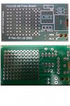
That's left me with the feeling that I really should bread board this thing so I understand what it does. It's really dificult for me to see what's going on with the conductive lines being on the other side from the component position markers. But with things like R1 doing it's thing I'm left feeling that I cant trust what I'm doing with the bread board.

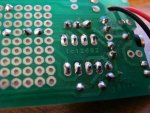
I took a photo of the board both sides and flipped the image of the conductive lines so they match up, and I still cant see what that R1 does.

I dont understand some bits of the 08 protoboard.jpg
 

Dippy

Moderator
Dave, that one was mentioned on a while back on this rapidly evolving thread :)

120: have you actually rubbed a DMM (set to 'ohms' or 'continuity') around the board?
Compare the component values on the Project Board with the 08M Pinout circuit in Manual Number 1.

The online PICAXE-08 board Kit manual doesn't have a schematic sadly (well, I can't see one and it really should have one) , but you should be able to follow where R1 may go.
(R1 = 10K , so where is 10K used on the download circuit?)
Clue: check R2.
So, dig out the DMM and get beeping or dig out your eyeglass and get squinting ;)

At this level think of capacitors as local reservoirs. I think you have discovered that. They don't short DC (unless failed).
 

SAborn

Senior Member
The basic circuit is like this schematic below, you should find the 2 pads next to each other are joined together, that explains where R1 is attached to.

The schematic dont show C1 (cap) but you have worked out where that goes already.
 

Attachments

Marcwolf

Senior Member
Hi Dave.
If you look very closely at the board you will see the that trace on the edge actually joins R1 and R2 together. R2 then goes off to the stereo socket for the download cable.

If you look at the serial download circuit int the PicAxe manual Part 1 (page 44 pn mine though depending on the one you have it be close re pages)
you will see that the 10K and the 22K are joined together. Which corresponds to what you can see on the board. And really that is the basis of the whole board.

The other side of the 10K goes to ground which is the outermost track that runs around the board, and the other side of the 22K goes to pint 2 of the Picaxe.. Which is it's serial input.

All boards are akin to a roadmap for the curcuit. Often a drawing shows the shortest distance between two point - but the actual board may need to wind the wires around the components to get to their destination. But the end result is the same - electricity gets from one point to another.

Capacitors can be though of as reserviors to hold excess current until needed
Resistors are like taps - reducing the flow by a precise amount
Transistors can act as switches or flow controllers - akin to a large pipe with a valve on it. Little effort is needed to turn the valve but it controls a Lot of flow
IC's - Office blocks performing a particular function. You generally don;t need to know everything that goes on in them - but you know what department to call when you need something. Like input, output, supply etc.

I still remember going through the basics.. Have fun, take care, and keep learning. At 51 I am still learning.

Growing old disgracefully
Dave
 

120ThingsIn20Years

Senior Member
Quite right you are! Sorry about that.

I had to use my camera to see it.

I'm guessing that means I can no longer fool myself that I dont need glasses :(
 

120ThingsIn20Years

Senior Member
Be advised, if using both solder and tinned copper wire in a project and are in the habit of using that last two inches of solder, then you will be aware that the reason the solder isn't melting into the joint is because it is actually a short length of tinned copper wire.

I used to find that awareness of such things and the heat from the iron travelled at about the same rate . . . ouch!
Too late, but thanks for the heads up anyway :)
 

120ThingsIn20Years

Senior Member
Thanks to all who I havnt thanked yet, you people have been amazingly helpful.

I think I'm getting there.

I bought a board and some resistors.


Me: "I need a project board, and 2 dozen assorted components."

Shop guy: "Sure thing what components are you after?"

Me: I dont know, just anything cheep"

Shop guy: "Oooooo Kaaaaayyy.

Shop guy in a very slow, very loud, and very clear voice : "that will be six dollars please."


I think it went quite well really :)

So...

I think I can solder!

This first pic was done from right to left with my 25watt soldering iron. I think my problem was not exposing enough iron to the surfaces, and not having a "wet" tip (thanks whoever it was that reminded me of that)

I think the best one is in the centre. Would that be right, is that what I'm after. Less bulb shaped look?

first few from right to left 25 watt.jpg

Then I tried a different soldering iron. This one was 75 watt.

this picture runs from left to right.

The first one worked really well, the second ok, and the third went all china syndrome on me. I'm guessing the soldering iron was still warming up.

That (and remembering the "wet tip" tip - and everybody else's input) finally made it stick in my head that I wasn't seeing enough heat.

So I went back to the 25 watt soldering iron, but stooped using just the very point and used a little more of the side as well as the tip.

I think the next few (starting at 4th from the left) worked pretty well.

second batch from left to right 1st 3 70watt then 25 watt.jpg
 

SAborn

Senior Member
They all look exceptable other than one (bottom photo 3rd form the left) Gee i have seen a hell of a lot worst from folk who claim they can solder.

Good work.
 

graynomad

Senior Member
As SAborn says they are mostly OK, I would suggest that you should be aiming for something like #s 5, 6 and 8 on the second photo.
 

120ThingsIn20Years

Senior Member
5,6 and 8, yeah good, that's what I would have said. So at least I know what they should look like :)

Even the ones that dont look so good (except 3 of course) have held well and cant be wriggled lose or anything.

How hard is it to deal with a stuff up like 3? does the actual board get damaged easily, or is it just a case of cleaning it up and doing it again?

I saw someone on youtube soaking up solder with what looked like the braid from the power pickup from my childhood slot car set.

Is that how you would deal with an effort like 3?

I guess you don't really need to use that bit of the printed circuit if I destroyed a conductive line on a real project. I could just join the required components directly together with some wire and bypass the damaged bit.
 

SAborn

Senior Member
Solder wick (braid) is one method of removing solder, i dont much like it and rather use a solder sucker, its a bit like a syringe with a spring in it, and you melt the solder then release the plunger on the solder sucker which vacuum sucks the solder up.

You can over heat a pad to the point it will peel off the board, but a little care and this should not happen.
 

Dippy

Moderator
Yes, some good ones there. Did you clean the board first?
Nude copper can get grubby and a good rub with a brass-wire/fibre brush followed by IPA+rag can help. I've had old stripboard that needed a lot of rubbing to get quite quick (<2s) solder joints.

I don't mean to sound rude, but a 75W iron is well OTT for small pads.
Assuming the iron tip temp reflects 75W power you could easily damage pad/track/component with repeated or prolonged use - especially if you have to do rework.

What make of iron? Is it a brand that any of us have heard of?

And that's some very fluxy solder, even accounting for the loads-a-solder you've put down.
I'd suggest getting some flux cleaner to remove the sticky goo afterwards.
Electrolube FluxClene , Servisol flux remover 160 and FluxOff work well.

What sort of time did you spend on each pad? Hopefully no more than a couple of seconds.
Anyway, you're getting there. Well done. Don't forget, we ALL make cockups now and then so don't worry.

Have you got a wet sponge to keep rubbing tip?


Braid can work quite well, it works even better if you wet it with a flux pen first. And if you don't keep it hot on fine-pitch ICs it can get 'stuck'.
Desolder suckers are good but they vary in quality.
I've used some with so much spring 'recoil' that they jump. We have about 20 at work. The more expensive ones seem slightly damped, but there are dozens on the market. An beware the tips - some melt too easily!
 
Last edited:

120ThingsIn20Years

Senior Member
Yes, some good ones there. Did you clean the board first?
I bought a new board and some new components, and just used them out of the packet.


I don't mean to sound rude, but a 75W iron is well OTT for small pads.
I only used the 75 watt for the first 3 on the left in the second photo. I think it worked well the first time because it wasnt hot yet. But I soon realised it was way too hot. The third one just boiled as soon as I touched it. So I went back to my 25 watt but with a little more understanding of heat I think.

I have no idea what brand they are. the 25 watt one is really old, and the 75 watt one was brand new that my mum bought for me a while ago from a $5 bin at a hardware.

And that's some very fluxy solder, even accounting for the loads-a-solder you've put down.
I'd suggest getting some flux cleaner to remove the sticky goo afterwards.
Electrolube FluxClene , Servisol flux remover 160 and FluxOff work well.
I think I'm meeting Pete soon for a soldering lesson, so I wont do anything to my first real board until then, I'll get some advice in the electronics store about solder etc. . The stuff I'm using comes in a red plastic spool and has no readable label.

Nicely equipped aren't I :)

What sort of time did you spend on each pad? Hopefully no more than a couple of seconds.
Anyway, you're getting there. Well done. Don't forget, we ALL make cockups now and then so don't worry.

Have you got a wet sponge to keep rubbing tip?
probably 2 or 3 seconds with the 25 watt iron. 1/4 of a second with the 75 :)

I have a wad of paper that I wet to keep the tip clean.

How often do you add solder to the tip, and how often should you clean the tip?

I'e been adding doing both between each component to try to get the best chance of success. I figure by making sure everything is as good as it can be before I actually solder something, at least I can be sure It's my method that is off rather than a dirty tip or whatever.

Anyway, it seems to be going well, I thought It was going to take longer than it has to see any progress.

But I think I either have to stop drinking to stop my hands shaking, or perhaps drink a little more :)
 

120ThingsIn20Years

Senior Member
I've just made my 08 proto board on a breadboard.

I've never used a bread board before or ever assembled anything electronic.

Is there some way I can test to see if I've done it correctly before I plug the chip in?

Or better yet after I've put the chip in, but before I put power to it?

I cant find anything in the manuals.
 

Dippy

Moderator
If you get a soldering iron stand they usually have a sponge area.
The sponge is normally a special variety, not the stuff you clean your bicycle with.
Clean tip regularly, every few solderings, or more often if you have a large blob on the bit.

If the $5 iron is performing OK then that's fine. Not my choice though.
Cheapies (unless ex-good-quality-sold-off-cheap or a genuine bargain or plain luck) are cheap for a reason.
But if it works then hey-ho.

Never assume a board is clean enough - even straight out of the packet and, in particular, boards that are bare copper.
Cleanliness is next to Solderiness. Brass-wire or fibre brush plus IPA.

Avoid advice from the Electronics Store Saturday Boy. Choose someone with a beard that doesn't reek of alchohol.


Lordy! If you are shaking in the comfort of your kitchen then you'll be quaking when Pete gets to you :)
Take your iron along and show it to him.


TESTING.
Wise to test first. Many don't and then moan like hell. So, good for you.
You can test for short-circuits and correct resistances using a Multimeter referring to circuit in Manual 1.
Then power-up (sans chip) and test voltages at the approriate places.
But as you sound like you are worried I'd take the whole thing along to Pete.
 
Last edited:

120ThingsIn20Years

Senior Member
Thanks.

I hate waiting. I tend to rush it :)

I think I'll enter what I have done on the breadboard it into the PICAXE software without looking at the original printed circuit board. ie just copy exactly what I have. If it works in the software, I might power it up in the real world :)

I'm very poor BTW in case everyone is wondering why I dont just get on with it. I'm living on what should have been my retirement fund :)
 

Marcwolf

Senior Member
Thanks, nicely described and just when I needed it.

Does that mean you're a Ulysses member?
No <Laughs> And I'm not sure if they'd have me either even though I do ride motorbikes occasionally

Lets just say that my hubby of 16 years would attest to my general disgraceful behaviour.

Take care
Marc
 

Dippy

Moderator
"...without looking at the original printed circuit board. ie just copy exactly what I have. If it works in the software, I might power it up in the real world "
- good luck. We'll watch out for the next thread "Why did it blow up?" :)

Don't forget; being patient can save money.


"I'm living on what should have been my retirement fund"
- oh, so the lottery ticket didn't win then?
 

hippy

Technical Support
Staff member
Is there some way I can test to see if I've done it correctly before I plug the chip in?

Or better yet after I've put the chip in, but before I put power to it?
Check it, double-check it, triple-check it, pace round the room, check it some more, have a sleepless night, check in the morning ...

Even those having done it for years can dread throwing the power switch and you can't always avoid mistakes so the best thing is to minimise them.

The best tool for that is a bench PSU with current limiting as that should 'light up like a Christmas tree' if there's something wrong while hopefully protecting the circuit if there is. Failing that use batteries and lowest voltage possible; weak, low-mAh Alkaline batteries will be better than power-beasts which can deliver buckets of current. Don't even think about using a PC power supply !

Adding a diode between battery + and PICAXE +V input will prevent against reverse voltages

Build the absolute minimum circuit, which for the PICAXE is just the PICAXE and download circuit, and get that working first.

If you want to, post a photo of your board to the forum. There's no shame in playing safe. It's always at your own risk when you throw the switch but others will do their best to spot any potential problems.
 

120ThingsIn20Years

Senior Member
My computer with the serial ports just crapped itself :(

That's kind of put an end to todays fun, and anyway, the stereo plug doesn't reach the metal in my little breadboard.

But tomorrow, Ill pull a hard drive from something else and be back up and running.

So I went back through this thread and had a better look at this post.

That's a really clever way of reporting temperature without needing a display. It would also be readable from anywhere in the garden.

I love it.


48 and still in short pants and playing when every I am allowed.

Try something simple, the first thing I did in my hydroponic setup was to measure the temperature. If you want to open vents, I assume you too will want to do that at some set temperature. Here is a circuit and code to make a basic temperature sensor that flashes LEDs.
The Green LED should flash the current temperature, 2 long flashes and 4 short flashes is 24 deg.
The Blue LED will then flash the min temp in last 24 hours
The Red LED will then flash the max temp in lst 24 hours.
Code:
'Written/Modified 31-Aug 2011 by Terry Simmich
'Written for 28X2 (ported from 08M)
#picaxe 28X2
#terminal 9600
SetFreq M8
'Use DS18B20 as the temperature sensor 
'and displays the current Max and Min (Last 24 hours)
'-ve Temp is indicated by a series of rapid flashes initially
'Temperature is Blinked as a series of blinks for 10's followed by faster flashes for units.

'NOTE wait till LEDS start blink to re-program (F5)
'NOTE cant program while in a sleep mode.

SYMBOL  RedLED  = B.2   'Output 2 = PIN 23 connected to Red LED
SYMBOL  BlueLED  = B.1   'Output 1 = PIN 22 connected to Blue LED
SYMBOL  GreenLED  = B.0   'Output 2 = PIN 21 connected to Green LED
SYMBOL  TempPin   = C.0   'Input  0 = PIN 11 connected to DS18B20 Temp Sensor

SYMBOL BucketAdr  = B13
SYMBOL GMin  = B12
SYMBOL GMax  = B11
SYMBOL LMin  = B10
SYMBOL LMax  = B9
SYMBOL LoopCount  = W3
SYMBOL Temp  = B0
GOSUB ReadDS18B20    'Read current temperature
FOR B1 = 80 TO 127   '48 buckets, 24 for each hour Max and Min
 POKE B1,Temp   'Fill with default Initial Temp
NEXT B1     'Uses RAM addresses from 80 to 127 on a 08M
GMax=Temp     'Initilise these
GMin=Temp     
Goto StartHere
LOOP1: 
SLEEP 12 '30 Sec       'Drain drops to 170uA when napping
GOSUB ReadDS18B20    'Read current temperature
IF Temp < LMax THEN NoNewMax1  'Chech for a new Max or Min
 LMax = Temp    '60 min Max
NoNewMax1:
IF Temp > LMin THEN NoNewMin1
 LMin = Temp    '60 min Min
NoNewMin1:

GMax=LMax     'Set Max and Min to Current Max Min
GMin=LMin     'New 24 hour Max and Min
FOR B1 = 80 TO 103   'Calculate Max and Minfor last 24 hours
 PEEK B1,B2    'Get Temp value into B2
 IF B2 < GMax THEN NoNewMax
  GMax = B2
NoNewMax:
 B5= B1+24
 PEEK B5,B2    'Get Temp value into B2
 IF B2>GMin THEN NoNewMin
  GMin = B2
NoNewMin:
NEXT B1
 
LoopCount = LoopCount + 1
IF LoopCount < 76 THEN FlashLEDs 'Change 76 for how often a new bucket is used
 BucketAdr = BucketAdr + 1 'Start a new 1 hour block
 IF BucketAdr < 104 AND BucketAdr > 80 THEN NoMod
  BucketAdr = 80
NoMod:
 POKE BucketAdr,LMax  'Save Max Temp
 B5 = BucketAdr + 24  'offset to the Min-array
 POKE B5       ,LMin  'Save Min Temp
StartHere:     'Time for a new bucket every 
 LoopCount = 0   '24 hours/24+1 bucket=3456 /45sec= 76 loops
 LMax = Temp    'Reset ~60min MAX MINs 30 sec sleep and 10-15 for flashing
 LMin = Temp
 
FlashLEDs:
B3 = Temp
B7 = GreenLED
GOSUB DisplayTEMP    'Requires Temp in B3
B3 = GMin
B7 = BlueLED
GOSUB DisplayTEMP    'Requires Temp in B3
B3 = GMax
B7 = RedLED
GOSUB DisplayTEMP    'Requires Temp in B3

GOTO LOOP1

'================================================================
ReadDS18B20:
READTEMP TempPin, Temp
IF Temp > 127 THEN Neg1   'Add 100 to temp to make
 Temp = Temp + 100   'Comparisons easier for -ve numbers
RETURN
Neg1:
Temp = 100 - Temp - 128   'Add 100 to temp to make
RETURN     'Comparisons easier for -ve numbers
'================================================================
DisplayTEMP:    'Flash out the temperature 
IF B3 > 100 THEN SkipNeg  'Zero is flashes flooowed by nothing
B3 = 100 - B3 + 100   'Neg becomes Positive
FOR B8 = 1 TO 40    'Show Neg flashes really fast
 TOGGLE B7 : PAUSE 15  'Turn if ON/OFF
NEXT B8
SkipNeg:
B3 = B3 -100
B1 = B3 /10     'Tens value
W2 = 500
GOSUB Blink
B1 = B3 //10    'Units value
W2 = 150
GOSUB Blink
RETURN
'================================================================
Blink:
PAUSE 500
B2 = B1 - 4
Blink2:
IF B1=0 THEN NoBlink   'Pre-tested loop 0 to 9 blinks
 HIGH B7 : PAUSE W2  'Turn if ON
 IF B1 <> B2 THEN SkipExtraDelay
  PAUSE 150   'Extra Delay for the 5th flash
SkipExtraDelay:
      LOW  B7 : PAUSE W2  'Turn if OFF
 B1 = B1 - 1
Goto Blink2
NoBlink:
RETURN
'================================================================
View attachment 8948
 

John West

Senior Member
Even with a new 'blank' circuit bd pulled from a sealed plastic bag it's a very good idea to clean and lightly burnish the bd with a good brisk rubbing of alcohol and a scouring pad just before you begin soldering. (I use the green 3M pads. If you use steel wool pads be very sure that all steel residue is removed from the bd.) The bd may have oxidized a bit over time in the bag or it may have been coated with something to keep it from oxidizing but that is not all that conducive to good soldering. So always clean the bd first. You'll be glad you did.

That, and keeping your soldering iron tip properly 'wetted' are the two items I try the hardest to impress on newbies to soldering, as they seem to be the two important items most ignored.

The third item is to always have a damp sponge, or similar cleaning device to wipe off your iron tip after every few connections. (I do it after every connection on difficult projects.) Then wet the tip again with fresh solder, and have at it. It will help make each connection clean and consistent.

And that is about as much as I know about cold fusion, although my name appears on a patent regarding possible methods of "controlling" a cold fusion reaction if one is ever produced. (I'm keeping my fingers crossed.) :)
 
Last edited:

boriz

Senior Member
Forget lead-free solder. I understand the need for it in large manufacturing, but it's a pointless hindrance to hobbyists. Always use normal 60/40 tin/lead solder, still easily available. I would add to the good advice above by saying, when you have finished soldering and turn the iron off, leave a nice big blob of solder covering the tip. It prevents oxidization and the tip lasts longer.

This is the soldering technique I have always used. With my trusty old 18W Antex with a small angled oval tip. It works for me:

(After making sure the pads and component legs are clean. I usually go over the copper with wire wool before starting.)

-Align the component and apply a small quantity of flux paste directly to the area. (I usually use a matchstick or something similar)
-Wipe the iron tip and apply it to the solder to gather a small blob on the tip.
-Apply the tip+blob to the component and pad so that the iron heats both simultaneously and the solder can flow onto both. Hold for 2 seconds.
-Quick visual inspection then move on to the next.

Using flux this way causes the pad and component leg to literally 'suck' the solder off the tip. You can get great joints, and the other benefit of course is that you don't need another hand to hold/apply the solder.

Note. Once the solder is on the hot iron, don't leave it there too long or it starts to go 'off' and becomes harder to work with.
 
Last edited:

John West

Senior Member
I agree with boriz (and others) on the lead free solder. For hobbyists, it's just not as good as the lead-based solders and it can actually cause additional problems beyond not flowing very well.

Do carefully clean the leads on any device that is to be soldered, especially if the leads have a dull appearance or seem almost black. Those are signs of severe oxidation on the lead. Leads really should be quite shiny. Suspect those that aren't. As I often use surplus components that have been around long enough to get severe oxidation on the leads, I regularly use a razor knife to scrape the leads clean. Oxide covered leads just don't allow solder to adhere worth a darn.

Note that IC pins can get oxidized just as badly as resistor or capacitor leads. The time you spend cleaning them off is time well spent, as it's a real pain trying to clean the leads or get solder to flow properly on oxidized pins once the part has been partially soldered in place.

Essentially, properly prepare the bd, the component and the iron for each connection and all will go well. Get sloppy or lazy about such preparation and things may not go so well. Even though I've been soldering for 50 years and have a NASA soldering certification, I sometimes get lazy about proper preparation and will suffer a poor solder joint because of it. Years of solder practice doesn't help much if the devices and bd to be soldered aren't clean.

I also note the awkwardness of attempting to write clear prose on this topic when the spelling for the name of the naturally occurring element "lead" (Pb) is identical to that of a component connecting "lead," even though they are pronounced quite differently. It's a good thing we aren't also discussing the lead time on leaded leadless components.

And why read what one has already read?
 
Last edited:

moxhamj

New Member
And if anyone is still feeling generous after all that, I cant find an answer to this...

Does a resistor waste voltage, like a leak in a hose, or does it restrict voltage like a tap?
I'm not sure if this got answered along the way, but to answer this, a resistor is exactly like a tap. To continue the water analogy, voltage is pressure and current is flow. A resistor is a tap. A capacitor is a small tank on a hillside. (A battery is a very large tank on a hillside). An inductor is a long length of pipe, preferably made of steel because water hammer works better with a pipe that is not stretchy like plastic.

For a capacitor, the energy is stored as pressure. For an inductor the energy is stored as current, ie the flow.

If you turn on a tap connected to a long steel pipe then suddenly turn it off you get water hammer, which is a sudden rise in the voltage/pressure.

You can use this to change voltages and I mention this because this leads to a discussion of switch mode power supplies, and the advantage of a 'switcher' is you can convert your 12V from your battery to 5V with almost no energy loss. That means minimal heat loss, and this could be relevant if you are running lots of servos. For the moment though, stick with 7805 regulators.

I am really impressed that you asked the question about what a resistor is, and even thought of the tap analogy. That shows great insight into the way electronics works. Keep the questions coming!

James Moxham (2 years younger than you and living in the same state)
 
Last edited:

120ThingsIn20Years

Senior Member
John West

All noted and filed away.

Thanks.


And this...


Look Mum! almost like a grownup! :)

Although now that I look at it up close there is a gaping hole or two.


120 things in 20 years - electronics - PICAXE 08 proto board.JPG
 

120ThingsIn20Years

Senior Member
I also note the awkwardness of attempting to write clear prose on this topic when the spelling for the name of the naturally occurring element "lead" (Pb) is identical to that of a component connecting "lead," even though they are pronounced quite differently. It's a good thing we aren't also discussing the lead time on leaded leadless components.
That's the stuff of Mars mission disasters.

"Take plenty of spare lead" :)
 

120ThingsIn20Years

Senior Member
Dr_Acula


Thanks.

Just keep the answers coming :)

I'm really scared everyone is going to snap out of it and stop being helpful all of a sudden :)

I really have had my share of luck already with the quality and quantity of the response.
 
Last edited:

SAborn

Senior Member
You should be teaching.
Errrrr? no thanks, a volunteered reality check from time to time is enough for me, i feel if we all do our bit from time to time to help others it should all get covered.

Secondly..... God help the poor students if i did, thought i done a pretty good job to confuse you today, as you have been rather quite ever since im guessing your brain is still in melt down. (or are you still sorting through the box of junk).

Seriously the OP mastered the assembly and soldering rather easy and quickly, the cheapy iron he has is a early Scope and not so bad for a starting tool, The solder he had was 1.5-2mm and a little large for circuit use and with some 0.71mm he mastered the task easy.

IMO the picaxe kit was simple but i felt it really lacked some instruction as it is a starter kit aimed at the beginner, there in not even a layout on the web site just a photo.........little poor there i think.
If you look on Peter Anderson site at the Kiwi board it is very well presented with information and think this simple board should have similar.

There was a moment when the first download failed and i had wondered why, hmmm my fault as didnt put the jumper on the serial out pin, (i never use them so didnt even think about it) problem fixed and all worked well then.

Better all brace yourself now for the 101 programming questions :)

Pete.
 

John West

Senior Member
We haven't even finished up with resistance, Pete. :)

The one difference in the water tap analogy that is important for resistors is that as current flows through them, voltage is dropped by them. As the "volume" of current flows through them, the "pressure" (voltage) drops. The difference between the input voltage and the output voltage means that there is a specific voltage difference between the input and the output that has been "dropped" by the resistor. Where did it go? It went into heat.

A resistor dissipates heat as it drops voltage, sometimes a little, sometimes a lot. The amount dissipated can be known by applying this formula: P=IR. That's Power (P) dissipated by the resistor equals current (I) times Resistance (R).

And no, I don't know why the letter "I" is used to represent current. Just a tradition, I guess. Perhaps someone else here knows. But by applying this formula you can calculate just how much heat will be dissipated (in Watts) by a given resistor at a given voltage or current.

That's important, because an incorrectly sized resistor can get too hot and start a fire, or pop like a fuse but in a much messier manner.

The other equation necessary for working with resistors is E=IR. That's E (for electromotive force {we call it voltage}) equals I (current) times R (resistance.) With this equation and knowing the values of any 2 of the variables you can calculate the third value. You will find many online calculators that will calculate these voltages, currents, resistances and power for you if you simply plug in the values you have. Just do a web search for "Ohm's Law calculator," or if you're handy with math just grab a pocket calculator and do it yourself.

Sorry if this sounds too inane. It's very difficult to know in the forum just what a poster already understands and what they don't, so I usually try to keep everything as simple as I can. It doesn't hurt those with a deeper knowledge, and it helps those who are looking at something totally foreign to them.
 
Last edited:

nick12ab

Senior Member
If you're solder has the following properties, it is leaded solder:
  • Strong smell (don't sniff this a lot)
  • Just an added note about this - "don't sniff this a lot" doesn't mean that I sniff it weekly or at all on purpose and I don't have to use it for solder identification either as I use the texture and how easy it is to melt, so "don't sniff this a lot" means that you should avoid sniffing it as the fumes are likely to be somewhat nasty or toxic.
 

nick12ab

Senior Member
Which is why our local ham radio club's project building group is called "Solder Sniffers."
I should also point out that the strength of the smell of leaded solder means that everybody would have smelt it at some point by accident unless they've always used a fan to blow away the fumes.
 

120ThingsIn20Years

Senior Member
[stuff deleted] a pretty good job to confuse you today, as you have been rather quite ever since im guessing your brain is still in melt down. (or are you still sorting through the box of junk).
nope, been busy

[more stuff deleted]

Better all brace yourself now for the 101 programming questions :)

Pete.
I've been busy working out this programming caper :)

so...

wait for it...
 
Top