For sale.Cold fusion reactor.Home made.Not working.$2000 ONO

nick12ab

Senior Member
@120thingsin20years

You've only changed the text label for the link in your signature - you need to change the hyperlink URL itself which can be done by putting the cursor somewhere in the hyperlink whilst editing it and clicking on the appropriate button in the editor.
 

120ThingsIn20Years

Senior Member
Another milestone in my education.

I just made a motor run via a transistor pair without setting fire to my lounge room.

Transistors are some powerful Voodoo.


I had no idea.


It's a lot like magic without all the ritual and stinky smelly stuff

It's no wonder you people can pass yourselves off as gods to the general public :)

Your typical, bearded, Hollywood wizard has nothing on a kid with a picaxe and a pocket full of mixed components.
 

SAborn

Senior Member
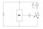
Why 2 transistors, you only need 1 transistor switching ground to the motor, also remember you should have a diode across the motor wires in reverse, to catch the EMF generated by the motor or the EMF might damage the transistor with regular use.

Like this in the schematic.
 

Attachments

SAborn

Senior Member
Then when you get the circuit above working , use pin2 on the 08m and try using PWM to control the motor speed.

That should be a good picaxe test for you.
 

120ThingsIn20Years

Senior Member
@120thingsin20years

You've only changed the text label for the link in your signature - you need to change the hyperlink URL itself which can be done by putting the cursor somewhere in the hyperlink whilst editing it and clicking on the appropriate button in the editor.
Doh!

thanks
 

120ThingsIn20Years

Senior Member
Then when you get the circuit above working , use pin2 on the 08m and try using PWM to control the motor speed.

That should be a good picaxe test for you.
I got it working, but I'm running my motor off the 3 cell battery pack and its under powered I think.

I tried ...

Code:
for speed = 200 to 255
     pwm c.1,speed,20
next speed
but it only kicks in at the very end of the cycle
 
Last edited:

120ThingsIn20Years

Senior Member
very cool

Code:
for Speed = MaxSpeed to MinSpeed step -1
pwm c.2,speed,10
next speed

for Speed = MinSpeed to MaxSpeed step -1
pwm c.2,speed,10
next speed
Interestingly I can hear the transistor cycling up.

Or does that mean I have the diode in backwards or something and I'm damaging my transistor?
 

120ThingsIn20Years

Senior Member
If I run that code so that it cycles up first rather than down, the motor doesn't start until "Speed" is close to 255, but once its running, it contines all the time from that point on.

Would that be because of a required extra surge to start the motor?


If so is there a way to give that surge so I could start it from low speed? I guess that would require some feedback from the motor to let the chip know it's started turning. I don't actually need to do that, it's just out of curiosity that I ask.
 

John West

Senior Member
Are you sure you aren't hearing the motor making noises before the current rises sufficiently to start it turning? I suppose the transistor die can "ring" if enough current is pulsing through it, but I'd more likely expect the noises to be coming from the motor windings.
 

120ThingsIn20Years

Senior Member
Are you sure you aren't hearing the motor making noises before the current rises sufficiently to start it turning? I suppose the transistor die can "ring" if enough current is pulsing through it, but I'd more likely expect the noises to be coming from the motor windings.
You are correct it is the motor.

I put a rod to my ear and put the other end to the motor body and got a stack of interesting sounds.

I made a recording of it but the uploader wont accept it even when zipped. Pitty as it's really interesting. Sounds like a digital ringtone when you can hear all of it. er complicated and digital sounding
 

Dippy

Moderator
"If so is there a way to give that surge so I could start it from low speed?"
- why don't you experiment? A slightly longer duty to start and then settle down. Why don't you play?

Also, try a 200-ish uF (microFarad) capacitor across it. +ve leg to top of motor and neg-ve leg to ground.
Sometimes this can act as a power reservoir to give extra boost and reduce noise.
I do this on H-Bridge designs for these reasons.
 

120ThingsIn20Years

Senior Member
"If so is there a way to give that surge so I could start it from low speed?"
- why don't you experiment? A slightly longer duty to start and then settle down. Why don't you play?
I did that, and got it to work, but I thought there might be a command to feed extra power and then detect that enough has been sent of something. I just gave it a short jolt to start it off and that worked fine.

now I'm working on running 12 volts through to the motor without turning everything else to toast :)
 

Dippy

Moderator
There isn't a command for that... it's down to you.
Try the capacitor if you have one in your drawer. Many people like to put a small ceramic across the windings/brushes too.
 

120ThingsIn20Years

Senior Member
Thanks.

I just keep turning it on every now and again as I'm searching for info on my next step :)

It's funny how amusing a motor changing speed up and down can be, when you've made it do it yourself :)
 

SAborn

Senior Member
Try advancing to the next step of reading the value of a pot and putting that into program to adjust the speed up and down by turning the pot.
 

120ThingsIn20Years

Senior Member
OK, will do.

But I need to stop using my battery pack to power the motor as well.

Can you give me a hint on a search term for running a 12 volt supply to the motor, and using the transistor as a switch to control it?

I've been trying to find it for ages. Am I just wrong in thinking I can do that?
 

120ThingsIn20Years

Senior Member
The only manual reference to anything that makes me think it might have something to do with what I'm trying to do I found a few hours ago and since I've been trying to find a circuit diagram to make me understand.

" Note that if a different power supply is used for the signal lamp, the 0V rails of each power supplymust be connected to provide a common reference"

This seems to indicate that I should connect the - terminal of a 12 volt power supply effectively to a chip pin.

I thought the idea was to avoid that kind of 12 volt thing, and I also thought a loop allowing all electrons to get back to where they started was required.

So the last couple of hours has been spent trying to find a circuit diagram to confirm what I need to do.

The fact that I cant find one makes me think that either I dont know the correct search term, or that it cant be done with a transistor.
 

sedeap

Senior Member
Maybe this info helps...

Best practices: (at least to me)


  • Isolating all from main Supply Lines
  • Using a switching PS just for IC and Inputs (just a mobile phone charger) plus 7805 regulator and diode bridge
  • Using OptoTransistors to isolate the outputs, or reed relays (and SSR)
  • Using Terminal blocks (screw type) to ensure contact and modularity
  • Give a coat of WD-40 contact oil to any wire tip before put in terminal block (if I cant melt solder on it)

Then you can use any power to run peripherals like motor, servos, switches or relays, even 220v ilumination or contactors.
Usually I use car battery or Alarm battery as PS but sometimes need to hang on Main Lines PS just for House lights or Pool water pumps
My best friends in that case are MOC3020 and BT137 , they work like a charm.

I wondering if there are some thread or repository with the usual Datasheets around PICAXES develompments...
Interesting challenge... do a Guide for usuals with examples, in the forum.

Hope that will help you 120T...


C U pal...
 

eclectic

Moderator
The only manual reference to anything that makes me think it might have something to do with what I'm trying to do I found a few hours ago and since I've been trying to find a circuit diagram to make me understand.

" Note that if a different power supply is used for the signal lamp, the 0V rails of each power supplymust be connected to provide a common reference"

This seems to indicate that I should connect the - terminal of a 12 volt power supply effectively to a chip pin.

I thought the idea was to avoid that kind of 12 volt thing, and I also thought a loop allowing all electrons to get back to where they started was required.

So the last couple of hours has been spent trying to find a circuit diagram to confirm what I need to do.

The fact that I cant find one makes me think that either I dont know the correct search term, or that it cant be done with a transistor.
Have a look at M.3, pages 6, 8 and 12.

e
 

120ThingsIn20Years

Senior Member
Thanks eclectic, that's what I've been looking at, but they all use one power source and only make a passing reference ( "Note that if a different power supply is used for the signal lamp, the 0V rails of each power supplymust be connected to provide a common reference") without actually mentioning what that means :)

I'm trying to find a circuit diagram where there is a second power source so I can be sure I know what to do. Once I do, my 2 hour search can turn into a 12 second job well done :)
 

120ThingsIn20Years

Senior Member
Thanks sedeap,

That first bit is what I'm trying to do for the first time :)

It's really tricky to search for stuff when you dont know the terms.

I'm trying lots of things like

"transistor switch 12 volts"

so far a google search for "two power supplies one transistor" has been the most promising

turning up http://www.kpsec.freeuk.com/trancirc.htm
"
A transistor can also be used to enable an IC connected to a low voltage supply (such as 5V) to switch the current for an output device with a separate higher voltage supply (such as 12V). The two power supplies must be linked, normally this is done by linking their 0V connections. In this case you should use an NPN transistor
"

Unfortunately the diagram just shows one power supply as well, but I guess that means I just cross the wires and hope
 

sedeap

Senior Member
OOOPPPPSSSSSsss...

Sorry 4 your loss pal... RIP little Chip...

Do yourself a favor and avoid mix PS (PowerSource)
Just use a Opto or reed relay to drive the power to motors or lights... KPoM (Keep Peace of Mind)
Separate the Output Circuits from IC...
And always use a diode protection to save from BackPeaks...

C U pal...
 

120ThingsIn20Years

Senior Member
Sorry 4 your loss pal... RIP little Chip...

Do yourself a favor and avoid mix PS (PowerSource)
Just use a Opto or reed relay to drive the power to motors or lights... KPoM (Keep Peace of Mind)
Separate the Output Circuits from IC...
And always use a diode protection to save from BackPeaks...

C U pal...
I thought I was separating the output circuits from the ic by using a transistor.

I'm trying to run my 12 volt motor from a 12 volt supply, and run my chip from a 3 cell battery pack currently showing 4.2 volts.
 

hippy

Technical Support
Staff member
" Note that if a different power supply is used for the signal lamp, the 0V rails of each power supplymust be connected to provide a common reference"

This seems to indicate that I should connect the - terminal of a 12 volt power supply effectively to a chip pin.
I think you are reading things into what was said which were not said.

I thought the idea was to avoid that kind of 12 volt thing, and I also thought a loop allowing all electrons to get back to where they started was required.
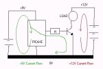
The attached circuit may help.

The PICAXE is on a 5V supply, the load is on a separate 12V supply. The 0V track is the common join between the two supplies. Current flow for the +5V is in a loop on the left, current flow for the +12V is on the right.
 

Attachments

Last edited:

120ThingsIn20Years

Senior Member
Thanks hippy.

That's just what I needed.

And also what I was trying to do when everything went dark :)

I think I actually fried the transistor.

Perhaps my diode is back to front or something.

After it had a little rest, the chip still takes a program and makes a LED on pin 1 flash.

Thanks again.
 

sedeap

Senior Member
PS (Power Source)

Ok...

Follow the manual and do a Power Source for IC ... only, & save your batteries
Then, feed the IC and analog parts with that PS
for outputs... just after the IC, put a resistor&diode to avoid BackPeaks and feed a ReedRelay to handle charges and different PS&Volts
If you want, also can use a OptoCoupler (Optic Switch) just like your use a LED (in fact is a LED inside)
Or also can use a Old&faithful mechRelay... as switch

if you want I can send you a Diagram of one 220V device timed with a PICAXE IC

C U pal...
 
Last edited:

hippy

Technical Support
Staff member
Perhaps my diode is back to front or something.
Perhaps, but what diode ? I admit I've not been following the full thread but it always helps to post a circuit diagram showing what you are doing, especially if you are throwing things together to see what works or not.

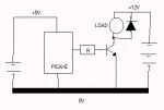
If it's an inductive load then the back-emf diode should be as follows ...
 

Attachments

Last edited:

hippy

Technical Support
Staff member
@hippy ... Battery polarities in post #273 diagram?
Yes, well spotted - I got that completely wrong ! I can never remember what the correct symbol is so guess I should have checked first.

I'll update them to be correct.
 

120ThingsIn20Years

Senior Member
I think I did fry the chip after all.

08M - I was getting a LED connected to C.1 via a 330 ohm resistor flashing very weakly when nothing in the program pointed to c.1

Q. Can a chip still load a program, and debug etc, but still be fried?

Code:
for speed = maxspeed to minspeed step -1
     pwm c.2,speed, 10 
     debug
next speed
There's nothing is that code that could be misinterpreted and that should make C.1 high is there? maxspeed and minspeed are 255 and 200.

Keeping in mind the LED is hard wired to the output marked on the proto board as 1, and my little project board has been flashing the led based on high c.1 commands the entire time, and nothings changed there.
 

SAborn

Senior Member
No, but if the led is connected to C.0 it will flash when Debug is in the program as there is data going out the serial out pin which is C.0, are you 100% sure there is no small solder bridges between C.0 and C.1 tracks anywhere, as this is the first time you have used debug and pin C.0 to see if there is a problem with the circuit and a short between the tracks somewhere.
 

120ThingsIn20Years

Senior Member
SABorn

I replaced the chip and got it working as per your emailed circuit diagram, info about diodes etc etc etc

Is it ok if I post the info in your emails here, because there are a few total new comers in my position following this thread that might be helped by the info?
 

John West

Senior Member
Yes, well spotted - I got that completely wrong ! I can never remember what the correct symbol is so guess I should have checked first.

I'll update them to be correct.
I keep screwing that up as well. I've learned to put big plus and minus signs on my battery schematic symbol, especially as there are many other folks who might look at the schematic and might have the same problem hippy and I have. I also always put a plus sign on all of my polarized capacitor symbols as well, as while the commonly used US symbol shape supposedly indicates body direction, and is supposed to have the plus sign when it is a polarized cap anyway, but some folks use the symbol direction indiscriminately for nonpolarized caps, so that little plus is especially important. Belt and suspenders.

As I work with electronics, year upon year, the thing that I continue to learn more of is the importance of attention to detail. I'm a sort of sloppy person about everything but electronics, but the lesson of being careful and paying attention to detail continues to get driven home further with every project. Working as a one-man-show on my projects, and slipping slowly into my dotage, it's great to have a forum available where there are folks who also pay attention to the details of circuits and would catch my mistakes.
 
Top