Rainwater tank controller
- Thread starter marzan
- Start date
marzan
Senior Member
Well after some reading I have some issues with hooking up the LCD I used another tutorial, which I think might have been Hippy`s to hook it up to a 28X2. I went back and found the code, but it wont compile due to syntax errors here:
SYMBOL get = b11
SYMBOL byte = b12
SYMBOL rsbit = b13
I found Nicks explanation easier to follow,but I think it uses different pis as it says :
symbol lcddata = pinsB
The way I have it hooked up is :
Backlight to B.1
RS TO B.2
E TO B.3
DB4 TO B.4
DB5 TO B.5
DB6 TO B.6
DB7 TO B.7
In hippy`s tutorial it talks of using the peek command to use the B.0 and B.1 pins, so tht`s why I used B.1 as the backlight pin.
I am feeling a bit out of my depth here, But I still like the idea of a parallel interface, and I guess once you get your head around the idea the first time it will be worth the effort. Hope this post isn`t too confusing.
Marz
There is several ways to do it and it all depends on what degree of resolution you need from your readings.180R doesn't sound like much to put into a voltage divider setup. Is there some way I can do it differently, say with an OP AMP?
My personal preference is to use a 16 bit ADC chip via I2C, its simple and easy, but not to say a opamp wont do a better job, it will with the right opamp, then you have the problem of working with a opamp, its not hard, but can be a daunting task if you have no understanding of working with opamps.
My best advice is if 10 bit ADC (picaxe) is not a good enough result then drive down the road and visit me, and i will give you a 16 bit ADC chip (albeit SMD) to try out.
I havent checked your design to see if the I2C pins are free to use such a chip ( hint i always reserve the I2C pins as a last resort to be used in a circuit design)
Once you have worked with 16 bit ADC data and a picaxe then its hard to go back to 10 bit data.
IMO if rev-ed sold a 16 bit ADC x I2C board then many ADC math problems would be solved that we always encounter with the picaxe 10 bit data.
Its a difference of working between 0 - 1024 bits for 10 bit data, and 0 - 65535 bits of data for 16 bits, its a huge difference!!!!.
Marzan,
Please list what picaxe pins connect to what pin on your LCD, because half the battle of making LCD code work is to know what pin talks to which pin where, its a sequence of procedures that must work in order, so if you change pins then you change the order the works in. And hence the code must change to suit your circuit layout.
Please list what picaxe pins connect to what pin on your LCD, because half the battle of making LCD code work is to know what pin talks to which pin where, its a sequence of procedures that must work in order, so if you change pins then you change the order the works in. And hence the code must change to suit your circuit layout.
westaust55
Moderator
GET is a BASIC program command to retrieve data from X1/X2 scratchpad memory.... hook it up to a 28X2. I went back and found the code, but it wont compile due to syntax errors here:
SYMBOL get = b11
SYMBOL byte = b12
SYMBOL rsbit = b13
BYTE and WORD are reserved words. WORD is a parameter used in various program commands - cannot recall if BYTE is used alone anywhere.
As such GET and BYTE are reserved words by PICAXE BASIC and cannot be used as alias variable names with the SYMBOL statement.
See Appendices 1, 2 ans 3 in PICAXE manual 2.
You've used the 4-bit LCD interface and my tutorial currently only covers the 8-bit interface (because it's easier and less likely to scare off the newbies) but I might add a 4-bit one as well.I found Nicks explanation easier to follow,but I think it uses different pis as it says :
marzan
Senior Member
Right, This is a link to the original tutorial:
http://galia.fc.uaslp.mx/~cantocar/microcontroladores/PICAXE/PICAXE_LCD_INTERFACING.HTM
That has the pinout I used.
So I changed the reserved words to see if the code would run, but it has an error in this line:
here is the code as I have it now.
Marz.
http://galia.fc.uaslp.mx/~cantocar/microcontroladores/PICAXE/PICAXE_LCD_INTERFACING.HTM
That has the pinout I used.
So I changed the reserved words to see if the code would run, but it has an error in this line:
Code:
pins = bytee & %11110000 | rsbit ; Put MSB out first
Code:
        SYMBOL  BKLT      = 1
        SYMBOL  RS        = 2         ; 0 = Command   1 = Data
        SYMBOL  E         = 3         ; 0 = Idle      1 = Active
        SYMBOL  DB4       = 4         ; LCD Data Line 4
        SYMBOL  DB5       = 5         ; LCD Data Line 5
        SYMBOL  DB6       = 6         ; LCD Data Line 6
        SYMBOL  DB7       = 7         ; LCD Data Line 7

        SYMBOL  RSCMDmask = %00000000 ; Select Command register
        SYMBOL  RSDATmask = %00000100 ; Select Data register

        SYMBOL  retrve    = b11
        SYMBOL  bytee     = b12
        SYMBOL  rsbit     = b13


    PowerOnReset:

        GOSUB InitialiseLcd

    DisplayTopLine:

        EEPROM 6,("Hello")

        FOR retrve = 6 TO 10
          READ retrve,bytee
          GOSUB SendDataByte
        NEXT

    MoveCursorToStartOfSecondLine:

        bytee = $C0
        GOSUB SendCmdByte

    DisplayBottomLine:

        EEPROM 11,("World!")

        FOR retrve = 11 TO 16
          READ retrve,bytee
          GOSUB SendDataByte
        NEXT

        END

    InitialiseLcd:

        FOR retrve = 0 TO 5
          READ retrve,bytee
          GOSUB SendInitCmdByte
        NEXT

        ' Nibble commands - To initialise 4-bit mode

        EEPROM 0,( $33 )    ; %0011---- %0011----   8-bit / 8-bit
        EEPROM 1,( $32 )    ; %0011---- %0010----   8-bit / 4-bit

        ' Byte commands - To configure the LCD

        EEPROM 2,( $28 )    ; %00101000 %001LNF00   Display Format
        EEPROM 3,( $0C )    ; %00001100 %00001DCB   Display On
        EEPROM 4,( $06 )    ; %00000110 %000001IS   Cursor Move

                            ; L : 0 = 4-bit Mode    1 = 8-bit Mode
                            ; N : 0 = 1 Line        1 = 2 Lines
                            ; F : 0 = 5x7 Pixels    1 = N/A
                            ; D : 0 = Display Off   1 = Display On
                            ; C : 0 = Cursor Off    1 = Cursor On
                            ; B : 0 = Cursor Steady 1 = Cursor Flash
                            ; I : 0 = Dec Cursor    1 = Inc Cursor
                            ; S : 0 = Cursor Move   1 = Display Shift

        EEPROM 5,( $01 )    ; Clear Screen

        RETURN


 SendInitCmdByte:

        PAUSE 15                        ; Delay 15mS at 4MHz

    SendCmdByte:

        PEEK $30,rsbit                  ; Recover Out0 and Out1
        rsbit = rsbit & %11             ; Send to Command register
        GOTO SendCmdOrDataByte

    SendDataByte:

        PEEK $30,rsbit                  ; Recover Out0 and Out1
        rsbit = rsbit & %11 | RSDATmask ; Send to Data register

    SendCmdOrDataBye:

        pins = bytee & %11110000 | rsbit ; Put MSB out first
        PULSOUT E,1                     ; Give a 10uS pulse on E
        pins = bytee * %00010000 | rsbit ; Put LSB out second
        PULSOUT E,1                     ; Give a 10uS pulse on E

RETURNhippy
Ex-Staff (retired)
That is code written specifically for an 18X I believe and it won't work for other chips without alteration and it's not ideally suited to alteration.here is the code as I have it now.
As SAborn notes above; it's all about which PICAXE and which pins you are using. You need to match the code being used to that. There is parallel LCD driving code which has been presented on the forum which is generic and fairly easy to convert for any PICAXE and then easier to optimise for a specific PICAXE or I/O configuration. It is best to start with that.
marzan
Senior Member
I have decided to ditch the present board and revamp everything using Nick12ab`s tutorial on 8 bit connection as the basis for the new one.
I am going to put the 2 buttons ( up and down) on the same input pin to save a pin, but I think I will put the select on another pin so it can use an interrupt if that is the best way to get it to jump straight to the menu
Marz.
That sounds like the way to go Pete. Do you have a pinout and package of the chip?My best advice is if 10 bit ADC (picaxe) is not a good enough result then drive down the road and visit me, and i will give you a 16 bit ADC chip (albeit SMD) to try out.
I havent checked your design to see if the I2C pins are free to use such a chip ( hint i always reserve the I2C pins as a last resort to be used in a circuit design)
I am going to put the 2 buttons ( up and down) on the same input pin to save a pin, but I think I will put the select on another pin so it can use an interrupt if that is the best way to get it to jump straight to the menu
Marz.
0.88 Bar is about 12.76 PSI and to get that you would need about 30 foot head of water, so i would expect your pressure sensor will be working down in the bottom 1/3 of its range, that is not a lot of difference to work with..8Bar. I`m hoping that is enough pressure.
marzan
Senior Member
Hello. I have redesigned the board so it uses 8 bit interface with a 28x2 picaxe. can someone point out where I am going wrong with the following LCD code.
When I run this code:
I get the result I am after:
Screen -> I TANK PUMP MONITOR I
I I
I TIME: I
I I
When I run this code:
I get the right result as well:
I I
I I
I I
I<- menu I
But when I combine the two:
I get: I TIME: I
I <-I
ITANK PUMP MONITOR I
I MENU I
I must have missed something, but I can`t see it.
Marz.
When I run this code:
Code:
SYMBOL  BL = c.5				;BACKLIGHT
SYMBOL  RS = C.6
SYMBOL ENT = c.7
SYMBOL lcddata = pinsb


Main:
	high BL                       ;turn on backlight

	dirsb = 255        		;set pinsb to output

	low RS

	output ENT

	pause 100

	lcddata = %00000010 : pulsout ENT,30			'Clear display
	pause 10
	lcddata = %00111000 : pulsout ENT,30			'Function Set: 8-bit, 2 lines, font 8x5
	pause 20
	lcddata = %00001100 : pulsout ENT,30			'Display on/off control: Display on, cursor off, blink off
	pause 20
	lcddata = %00000111 : pulsout ENT,30			'Entry mode set: Increment, cursor shift
	pause 20

text:
	lcddata = %00000001 : pulsout ENT,50			'return home
	pause 20
	low rs
	lcddata = 128 : pulsout ENT,1
	high rs
	for b4 = 0 to 40
		lookup b4,("  TANK PUMP MONITOR      TIME:         "),lcddata
		pulsout ENT,1
nextScreen -> I TANK PUMP MONITOR I
I I
I TIME: I
I I
When I run this code:
Code:
SYMBOL  BL = c.5				;BACKLIGHT
SYMBOL  RS = C.6
SYMBOL ENT = c.7
SYMBOL lcddata = pinsb


Main:
	high BL                       ;turn on backlight

	dirsb = 255        		;set pinsb to output

	low RS

	output ENT

	pause 100

	lcddata = %00000010 : pulsout ENT,30			'Clear display
	pause 10
	lcddata = %00111000 : pulsout ENT,30			'Function Set: 8-bit, 2 lines, font 8x5
	pause 20
	lcddata = %00001100 : pulsout ENT,30			'Display on/off control: Display on, cursor off, blink off
	pause 20
	lcddata = %00000111 : pulsout ENT,30			'Entry mode set: Increment, cursor shift
	pause 20

text:
	lcddata = %00000001 : pulsout ENT,50			'return home
	Pause 20
	low rs
	lcddata = 192 : pulsout ENT,1
	high rs
	for b5 = 0 to 19
		lookup b5,("<- MENU        "),lcddata
		pulsout ENT,1
	next
I I
I I
I I
I<- menu I
But when I combine the two:
Code:
SYMBOL  BL = c.5				;BACKLIGHT
SYMBOL  RS = C.6
SYMBOL ENT = c.7
SYMBOL lcddata = pinsb


Main:
	high BL                       ;turn on backlight

	dirsb = 255        		;set pinsb to output

	low RS

	output ENT

	pause 100

	lcddata = %00000010 : pulsout ENT,30			'Clear display
	pause 10
	lcddata = %00111000 : pulsout ENT,30			'Function Set: 8-bit, 2 lines, font 8x5
	pause 20
	lcddata = %00001100 : pulsout ENT,30			'Display on/off control: Display on, cursor off, blink off
	pause 20
	lcddata = %00000111 : pulsout ENT,30			'Entry mode set: Increment, cursor shift
	pause 20

text:
	lcddata = %00000001 : pulsout ENT,50			'return home
	pause 20
	low rs
	lcddata = 128 : pulsout ENT,1
	high rs
	for b4 = 0 to 40
		lookup b4,("  TANK PUMP MONITOR      TIME:         "),lcddata
		pulsout ENT,1
	next

	lcddata = %00000001 : pulsout ENT,50			'return home
	Pause 20
	low rs
	lcddata = 192 : pulsout ENT,1
	high rs
	for b5 = 0 to 19
		lookup b5,("<- MENU        "),lcddata
		pulsout ENT,1
	next
I <-I
ITANK PUMP MONITOR I
I MENU I
I must have missed something, but I can`t see it.
Marz.
Last edited:
The first issue is that you have enabled display shifting by setting the least significant bit in the Entry Mode Set instruction to 1. Below is the code from my tutorial where the relevant bit is a 0.
Additionally you used the Return Home instruction instead of Clear Display in your display initialization.
The second problem with the combined code is that you've tried to send the clear display instruction (it's not return home as the comment says) while the RS pin is high. But all this should do is display CGRAM character 1.
Code:
	lcddata = %00111011 : pulsout enable,16			'Function Set: 8-bit, 2 lines, font 11
	lcddata = %00000001 : pulsout enable,608			'Clear display
	lcddata = %00001100 : pulsout enable,608			'Display on/off control: Display on, cursor off, blink off
[B]lcddata = %00000110[/B] : pulsout enable,16 'Entry mode set: Increment, cursor shiftThe second problem with the combined code is that you've tried to send the clear display instruction (it's not return home as the comment says) while the RS pin is high. But all this should do is display CGRAM character 1.
marzan
Senior Member
Hmmm.. Dumb mistakes by me.. I am a bookbinder and proof read every day, yet i didnt see the obvious mistakes. Have it working now. Thanks NickThe first issue is that you have enabled display shifting by setting the least significant bit in the Entry Mode Set instruction to 1. Below is the code from my tutorial where the relevant bit is a 0.Additionally you used the Return Home instruction instead of Clear Display in your display initialization.Code:lcddata = %00111011 : pulsout enable,16 'Function Set: 8-bit, 2 lines, font 11 lcddata = %00000001 : pulsout enable,608 'Clear display lcddata = %00001100 : pulsout enable,608 'Display on/off control: Display on, cursor off, blink off [B]lcddata = %00000110[/B] : pulsout enable,16 'Entry mode set: Increment, cursor shift
The second problem with the combined code is that you've tried to send the clear display instruction (it's not return home as the comment says) while the RS pin is high. But all this should do is display CGRAM character 1.
")
If I have read this thread correctly here is my 2 cents:
1. If you need to save pins (and/or code space) use serial displays like the AXE133Y instead of driving the display with you project Picaxe.
2. If you have enough battery power to run a pump for 5 minutes it's doubtful you need to be terribly concerned with power saving.
1. If you need to save pins (and/or code space) use serial displays like the AXE133Y instead of driving the display with you project Picaxe.
2. If you have enough battery power to run a pump for 5 minutes it's doubtful you need to be terribly concerned with power saving.
If you need more pins, use a PICAXE-40X2. Serial LCDs1. If you need to save pins (and/or code space) use serial displays like the AXE133Y instead of driving the display with you project Picaxe.
westaust55
Moderator
Just so you understand why that line fails,So I changed the reserved words to see if the code would run, but it has an error in this line:
Code:pins = bytee & %11110000 | rsbit ; Put MSB out first
With X1 and M2 parts (and their predecessors) the IO pins were in general fixed to one direction and pins on the left of the equals (=) meant the outputs whereas pins on the right of the equals mean the inputs.
With the newer M2 and X2 PICAXE chips, nearly all pins can be inputs and outputs so there is a need to designate which port is involved.
Like is recommended to use the port.pin nomenclature for individual IO pins (eg HIGH B.5, LOW B.2, etc).
when you want to control all 8 pins for a port in one command rather than the old "pins" variable you must now indicate the port involved hence you must use "PinsB = ...", PinsC = ...", etc.
How? I have never had a problem even with multiple serial devices receiving data multiple times per program loop.If you need more pins, use a PICAXE-40X2. Serial LCDscanwill cause problems with interrupts, timers, servos, background i2c, background hardware serial and others so it's best to avoid them if there is the possibility that one of those will be needed or they are needed.
But those are all devices that receive serial from the PICAXE. The problems occur when the PICAXE has to be receiving the serial data or another IC is the i2c master and the PICAXE has to obey whatever clock signal speed it wants to use.How? I have never had a problem even with multiple serial devices receiving data multiple times per program loop.
I think you are confusing I and O.But those are all devices that receive serial from the PICAXE. The problems occur when the PICAXE has to be receiving the serial data or another IC is the i2c master and the PICAXE has to obey whatever clock signal speed it wants to use.
My comments were directed at the output LCD which appears to use 7 pins on the Picaxe and consumes quite a bit of (complex) program space. On the input side three Picaxe pins for buttons are trivial as is the code to implement them.
I like simple.
Imagine how much further along this project would be if the display functions were simple serout statements which could go to multiple LCDs if desired.
No I'm not. Using the serout command to control the LCD will disable all interrupts and cause problems with any interrupt-based things like background hardware i2c slave mode, timers and background hardware serial.I think you are confusing I and O.
My comments were directed at the output LCD which appears to use 7 pins on the Picaxe and consumes quite a bit of (complex) program space. On the input side three Picaxe pins for buttons are trivial as is the code to implement them.
Due to your high post count I'll defer somewhat.No I'm not.
I have never experienced any of these problems even though I have used timers and the DS1307 via i2c extensively with serial for LCD and data logging to SD cards. I don't want to drag this thread off course so your insistence should quickly provide proof via a code sample, reference to documentation or relevant forum posts. Failing that this discussion needs to move to another thread.Using the serout command to control the LCD will disable all interrupts and cause problems with any interrupt-based things like background hardware i2c slave mode, timers and background hardware serial.
marzan
Senior Member
1. I know I could use a smaller picaxe if I wished, and use an axe133. I have done so previously. I am treating this as a learning experience to see if I can nut out my project using one microcontroller. I have a crude plan of how I want to do it. I will use slot 1 to set up or change the RTC and any functions I need to set up the OLED, and possibly use a data eeprom for other settings that would not be held when moving slots. Being mindful of the issue Nick has mentioned, then move to the second slot for the program itself, using interupts to control manipulation of the switches, OLED and pump etc.If I have read this thread correctly here is my 2 cents:
1. If you need to save pins (and/or code space) use serial displays like the AXE133Y instead of driving the display with you project Picaxe.
2. If you have enough battery power to run a pump for 5 minutes it's doubtful you need to be terribly concerned with power saving.
2 The battery power is not the issue for the circuit. The rainwater and kids under the age of 4 is. I have several taps around the yard and have previously lost a lot of rainwater because I had not realised that one of the little grommets had managed to turn a tap on.
At present I am struggling to get the time to display on a certain line at a certain place. When time permits, I will take a picture of what I have so far to better explain what`s going on. Thanks for the help so far everyone.
Marz
Good idea - some relevant forum threads:I have never experienced any of these problems even though I have used timers and the DS1307 via i2c extensively with serial for LCD and data logging to SD cards. I don't want to drag this thread off course so your insistence should quickly provide proof via a code sample, reference to documentation or relevant forum posts. Failing that this discussion needs to move to another thread.
marzan
Senior Member
I have written the code for the startup screen :
Can anyone suggest any improvements to it?
Marz.
Code:
SYMBOL  BL = c.5								;BACKLIGHT
SYMBOL  RS = C.6
SYMBOL ENT = c.7
SYMBOL lcddata = pinsb
symbol seconds = b10
symbol mins = b11
symbol hour = b12
symbol day = b13
symbol date = b14
symbol month = b15
symbol year = b16
symbol control = b17


setup:
	output ENT								;set c.7 as output

	high BL                       				;turn on backlight

	dirsb = 255        						;set pinsb to output

	low RS								;command register

	pause 100

	lcddata = %00000001 : pulsout ENT,2				'Clear display
	pause 10
	lcddata = %00111000 : pulsout ENT,2				'Function Set: 8-bit, 2 lines, font 8x5
	pause 10
	lcddata = %00001100 : pulsout ENT,2				'Display on/off control: Display on, cursor off, blink off
	pause 10
	lcddata = %00000110 : pulsout ENT,2				'Entry mode set: Increment, cursor shift
	pause 10

Main:										;set PICAXE as master and DS1307 slave address

	hi2csetup i2cmaster, %11010000, i2cslow, i2cbyte	'set up RTC on I2C

	hi2cin 0,(b10,b11,b12,b13,b14,b15,b16,b17)		'read RTC
	debug
	pause 50

	low rs								'command register
	lcddata = %00000010 : pulsout ENT,2				'return home
	pause 10
	low rs								'command register
	lcddata = 128 : pulsout ENT,2					'Line 1
	high rs								'Data register
	for b4 = 0 to 16
	lookup b4,("  TANK CONTROLLER"),lcddata
	pulsout ENT,2
	next
	low rs								'command register
	lcddata = 192 : pulsout ENT,2					'Line 2
	high rs								'data register
	BCDTOASCII b12,b19,b20						'Change BCD to ASCII for transmission to LCD
	BCDTOASCII b11,b21,b22
	BCDTOASCII b10,b23,b24
	for b4 = 0 to 25
	lookup b4,("   TIME ",b19,b20,":",b21,b22,":",b23,b24,"    <-MENU"),lcddata
	pulsout ENT,2
	next

goto mainMarz.
hippy
Ex-Staff (retired)
I'd put that and similar in subroutines so the code becomes easier to use and more self explanatory. That can make it simpler to confirm code is correct and make it easier to debug and maintain ...low rs
lcddata = 128 : pulsout ENT,2
high rs
b0 = 128 : Gosub SendCommandToLcd
How the LCD actually interfaces to the PICAXE is then hidden away within those routines. You don't have to remember to set or clear RS in the main code and you can change those routines without altering the main code if you want to move to a different PICAXE, want different I/O pin connections, or want to use a different interface, serial or 4-bit, or need to tweak the timing.
Of course; it all depends upon what one considers an "improvement".
Does it work?Can anyone suggest any improvements to it?Marz.
My main advice is use SYMBOLS for all references in code:
Code:
'outputs
SYMBOL lcddata = pinsb
SYMBOL BL      = c.5								;BACKLIGHT
SYMBOL RS      = C.6
SYMBOL ENT     = c.7

'DS1307 variables
symbol seconds = b10
symbol mins    = b11
symbol hour    = b12
symbol day     = b13
symbol date    = b14
symbol month   = b15
symbol year    = b16
symbol control = b17

'DS1307 display variables
symbol hr10    = b19
symbol hr01    = b20
symbol mn10    = b21
symbol mn01    = b22
symbol sc10    = b23
symbol sc01    = b24

setup:
	output ENT								;set c.7 as output

	high BL                       				;turn on backlight

	dirsb = 255        						;set pinsb to output

	low RS								;command register

	pause 100

	lcddata = %00000001 : pulsout ENT,2				'Clear display
	pause 10
	lcddata = %00111000 : pulsout ENT,2				'Function Set: 8-bit, 2 lines, font 8x5
	pause 10
	lcddata = %00001100 : pulsout ENT,2				'Display on/off control: Display on, cursor off, blink off
	pause 10
	lcddata = %00000110 : pulsout ENT,2				'Entry mode set: Increment, cursor shift
	pause 10

Main:										;set PICAXE as master and DS1307 slave address

	hi2csetup i2cmaster, %11010000, i2cslow, i2cbyte	'set up RTC on I2C

	hi2cin 0,(seconds,mins,hour,day,date,month,year,control)		'read RTC
	debug
	pause 50

	low rs								'command register
	lcddata = %00000010 : pulsout ENT,2				'return home
	pause 10
	low rs								'command register
	lcddata = 128 : pulsout ENT,2					'Line 1
	high rs								'Data register
	for b4 = 0 to 16
	lookup b4,("  TANK CONTROLLER"),lcddata
	pulsout ENT,2
	next
	low rs								'command register
	lcddata = 192 : pulsout ENT,2					'Line 2
	high rs								'data register
	BCDTOASCII hour,hr10,hr01						'Change BCD to ASCII for transmission to LCD
	BCDTOASCII mins,mn10,mn01
	BCDTOASCII seconds,sc10,sc01
	for b4 = 0 to 25
	lookup b4,("   TIME ",hr10,hr01,":",mn10,mn01,":",sc10,sc01,"    <-MENU"),lcddata
	pulsout ENT,2
	next

goto main
Of course I'd do it with a serial LCD:
Code:
#picaxe 28x2

'constants
SYMBOL LCDbaud = n2400_8

'outputs
SYMBOL LCDpin  = B.1								'AXE133Y

'DS1307 variables
symbol secs    = b10
symbol mins    = b11
symbol hour    = b12
symbol day     = b13
symbol date    = b14
symbol month   = b15
symbol year    = b16
symbol control = b17

'DS1307 display variables
symbol hr10    = b19
symbol hr01    = b20
symbol mn10    = b21
symbol mn01    = b22
symbol sc10    = b23
symbol sc01    = b24

setup:

	pause 1000
	i2cslave %11010000, i2cslow, i2cbyte							'set DS1307 slave address

Main:

	readi2c 0,(secs,mins,hour,day,date,month,year)

	bcdtoascii hour,hr10,hr01
	bcdtoascii mins,mn10,mn01
	bcdtoascii secs,sc10,sc01

	serout LCDpin, LCDbaud,(254,1)										'clear display
	pause 30
	serout LCDpin, LCDbaud,(254,128,"  TANK CONTROLLER")
	serout LCDpin, LCDbaud,(254,192,"   TIME ",hr10,hr01,":",mn10,mn01,":",sc10,sc01,"    <-MENU")

	pause 10000

goto mainmarzan
Senior Member
You could indent the code in for...next loops to make it easier to read.Can anyone suggest any improvements to it?
marzan
Senior Member
Will do Nick. Thanks again for the tutorial on parallel interfacing. It`s where I got most of the info from to get this far.You could indent the code in for...next loops to make it easier to read.
Marz.
marzan
Senior Member
I have added a bit more code. There is a main screen which displays a initial screen:
___TANK CONTROLLER______
____TIME XX:XX:XX_______
_________________________
<-MENU__________________
When the menu button is pushed the screen changes to :
*_SET CLOCK_________
__DAYLIGHT SAVING___
__XXXXXX___________
__XXXXXX___________
When the menu button is pressed the asterisk moves down a line.
Here is the code:
That`s about the limit of my knowledge as to efficiency, so any possible improvements anyone can suggest would be great.I did toy with the idea of a lookup table. There is still plenty of room in that slot. As I mentioned previously will change slots once the clock is set if I cant get the rest to fit.
Marz.
___TANK CONTROLLER______
____TIME XX:XX:XX_______
_________________________
<-MENU__________________
When the menu button is pushed the screen changes to :
*_SET CLOCK_________
__DAYLIGHT SAVING___
__XXXXXX___________
__XXXXXX___________
When the menu button is pressed the asterisk moves down a line.
Here is the code:
Code:
	SYMBOL   BL = c.5								;BACKLIGHT
	SYMBOL   RS = C.6
	SYMBOL  ENT = c.7
	SYMBOL lcddata = pinsb
	SYMBOL seconds = b10
	SYMBOL mins = b11
	SYMBOL hour = b12
	SYMBOL day = b13
	SYMBOL date = b14
	SYMBOL month = b15
	SYMBOL year = b16
	SYMBOL control = b17


setup:


	dirsb = 255 							;set pinsb to output
	dirsc = 7      							;set pinsc

	high BL                       				;turn on backlight

	low RS								;command register

	pause 100

	lcddata = %00000001 : pulsout ENT,2	:pause 10			'Clear display
	lcddata = %00111000 : pulsout ENT,2	:pause 10			'Function Set: 8-bit, 2 lines, font 8x5
	lcddata = %00001100 : pulsout ENT,2	:pause 10			'Display on/off control: Display on, cursor off, blink off
	lcddata = %00000110 : pulsout ENT,2	:pause 10			'Entry mode set: Increment, cursor shift

Main:										;set PICAXE as master and DS1307 slave address

	hi2csetup i2cmaster, %11010000, i2cslow, i2cbyte	'set up RTC on I2C

	hi2cin 0,(b10,b11,b12,b13,b14,b15,b16,b17)		'read RTC
	pause 50

	low rs								'command register
	lcddata = %00000010 : pulsout ENT,2				'return home
	pause 10
	low rs								'command register
	lcddata = 128 : pulsout ENT,2					'Line 1
	high rs								'Data register
		for b4 = 0 to 16
		lookup b4,("  TANK CONTROLLER"),lcddata
		pulsout ENT,2
		next
	low rs								'command register
	lcddata = 192 : pulsout ENT,2					'Line 2
	high rs								'data register
	BCDTOASCII b12,b19,b20						'Change BCD to ASCII for transmission to LCD
	BCDTOASCII b11,b21,b22
	BCDTOASCII b10,b23,b24
		for b4 = 0 to 25
		lookup b4,("   TIME ",b19,b20,":",b21,b22,":",b23,b24,"    <-MENU"),lcddata
		pulsout ENT,2
		next
	if pina.3 = 1 then goto SETMENU1
	goto MAIN

SETMENU1:
	gosub SCREENCLR
		for b4 = 0 to 28
		lookup b4,("* SET CLOCK           *******"),lcddata
		pulsout ENT,2
		next
	LOW RS
	lcddata = 192 : pulsout ENT,2
	pause 10
	high rs
		for b4 = 0 to 28
		lookup b4,("  DAYLIGHT SAVING     *******"),lcddata
		pulsout ENT,2
		next
	wait 1
		do
		if pina.3 = 1 then goto SETMENU2
		loop

SETMENU2:

	gosub SCREENCLR
		for b4 = 0 to 28
		lookup b4,("  SET CLOCK           XXXXXXX"),lcddata
		pulsout ENT,2
		next
	LOW RS
	lcddata = 192 : pulsout ENT,2
	pause 10
	high rs
		for b4 = 0 to 28
		lookup b4,("* DAYLIGHT SAVING     XXXXXXX"),lcddata
		pulsout ENT,2
		next
	wait 1
		do
		if pina.3 = 1 then goto SETMENU3
		loop

SETMENU3:
	gosub SCREENCLR
		for b4 = 0 to 28
		lookup b4,("  SET CLOCK         * XXXXXXX"),lcddata
		pulsout ENT,2
		next
	LOW RS
	lcddata = 192 : pulsout ENT,2
	pause 10
	high rs
		for b4 = 0 to 28
		lookup b4,("  DAYLIGHT SAVING     XXXXXXX"),lcddata
		pulsout ENT,2
		next
	wait 1
		do
		if pina.3 = 1 then goto SETMENU4
		loop

SETMENU4:
	gosub SCREENCLR
		for b4 = 0 to 28
		lookup b4,("  SET CLOCK           XXXXXXX"),lcddata
		pulsout ENT,2
		next
	LOW RS
	lcddata = 192 : pulsout ENT,2
	pause 10
	high rs
		for b4 = 0 to 28
		lookup b4,("  DAYLIGHT SAVING   * XXXXXXX"),lcddata
		pulsout ENT,2
		next
	wait 1
		do
		if pina.3 = 1 then goto SETMENU3
		loop

SCREENCLR:
	low rs
	lcddata = %00000001 : pulsout ENT,2				'Clear display
	pause 10
	lcddata = %00000010 : pulsout ENT,2				'reuturn home
	PAUSE 10
	lcddata = 128 : pulsout ENT,2					'line 1
	pause 10
	high rs
RETURNMarz.
I'm glad you are making progress! It is great when things start doing something.
My opinion is that it is better to start at the core of your idea and work out. When one sets out to build an automobile one starts with the motor or rolling hardware, not the clock.
Others may differ but my goal is to get benefit from projects ASAP. That is why builders get a roof on a structure ASAP. I see WAY too many people that with the best intentions spend their time fiddling with the edges instead of starting at the core of an issue. This is fine if that is what you WANT to do. However it can lead to frustration and dropped projects since the real world benefits tend to only happen at the end of the project with that workflow. I'd rather get SOMETHING working quickly and fill in as time allows.
For example:
This is my lathe controller (the finished? project is here). I needed to cut a bunch of spacers so I built this. It didn't take long. It ran on that cardboard box while I made a bunch of these:
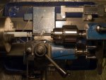
Functionality to change values, read RPM, calculate SFM were added later.
That is the way I tend to work.
I'm going to comment. Marz, you are free to follow whatever course you choose working on your project. My comments are for the benefit of the many lurkers that show up in the page counts.That`s about the limit of my knowledge as to efficiency, so any possible improvements anyone can suggest would be great.
My opinion is that it is better to start at the core of your idea and work out. When one sets out to build an automobile one starts with the motor or rolling hardware, not the clock.
There is a good starting point! Sensing water flow and stopping the pump after 5 minutes will give you an immediate benefit and make sure the project is viable. There is little point in continuing unless you can get this core bit of functionality 100% reliable.Hi everyone. I am starting a new project. I want to build a controller for my rainwater tank.
I want the controller to:
Limit the pump to run for a maximum of 5 minutes before shutting off the pump
Great second bit of programming to add. You don't have to be able to set the clock from a UI to do this. Get the desired functionality working first then add the UI. Might be easier to use an output from the irrigation system to bypass your Picaxe output though...UNLESS it is in a specified time period set to coincide with the irrigation system.
Here is a good third bit of HW and SW. The first two bits could be up and running while you got this working on a second breadboard. Once you have this working I'd add in functionality to prohibit or modify irrigation if the tank level was below a certain level.check the water level in the tank via a pressure sensor in the outflow pipe at the bottom of the tank.
Great ideas along with the UI stuff - once everything else is working.Dorji 433 MHz modules to also receive info onto a remote lcd screen (or in a perfect world an app on my computer)and a piezo to operate when tank low or time exceeded.
Others may differ but my goal is to get benefit from projects ASAP. That is why builders get a roof on a structure ASAP. I see WAY too many people that with the best intentions spend their time fiddling with the edges instead of starting at the core of an issue. This is fine if that is what you WANT to do. However it can lead to frustration and dropped projects since the real world benefits tend to only happen at the end of the project with that workflow. I'd rather get SOMETHING working quickly and fill in as time allows.
For example:
This is my lathe controller (the finished? project is here). I needed to cut a bunch of spacers so I built this. It didn't take long. It ran on that cardboard box while I made a bunch of these:
Functionality to change values, read RPM, calculate SFM were added later.
That is the way I tend to work.
Last edited:
marzan
Senior Member
@lewisg. Thanks for the input. The original idea has been through a lot of changes, mainly because of the tank level sensor. Sensors that some people have used have had problems, so while figuring that side of things I decided to start the Gui . learning to use an OLED in parallel mode was the original reason for building the whole thing. I' not too fussed on how long it takes to get finished. The journey is more fun than the destination.
I did use a similar approach to you and your lathe when getting my first milling machine going. everything was held together with rubber bands and sticky tape until I could get it making its own parts. Since then it has made me a new gantry mill with a VFD spindle and refitted a lathe to be CNC also. I cheated on the electronics though. Went out and bought geckodrives. As you said, get things going ASAP when you have spent all that money.
Marz.
Glad you took my comments as intended. I'm not trying to tic people off...@lewisg. Thanks for the input.
Have you tried on of these: HRXL-MaxSonar-WRM ?The original idea has been through a lot of changes, mainly because of the tank level sensor.
You are apparently quite handy with that mill! Nice boards!I did use a similar approach to you and your lathe when getting my first milling machine going. everything was held together with rubber bands and sticky tape until I could get it making its own parts. Since then it has made me a new gantry mill with a VFD spindle and refitted a lathe to be CNC also. I cheated on the electronics though. Went out and bought geckodrives. As you said, get things going ASAP when you have spent all that money.
Marz.
GUI on!
marzan
Senior Member
I have come up with the easiest solution (that I have found). I use diptrace for schematics and pcb layout. Export to mach3 for drill files(mirrored), export dxf (mirrored) bottom edge and cutout. Import DXF into D2NC(if sold with Mach3 it is really cheap but on its own still very cheap for all it can do) inside of mach3 to set up speeds/feeds and depths. and voila! boards can be milledYou are apparently quite handy with that mill! Nice boards!
GUI on!
marzan
Senior Member
I am attempting to program the screens. This code works as expected:
I want to put the values of b19 and b20 3 spaces over from the "SET HOURS". I want to do it after the the screen has loaded so I can alter just the variables with a + and - buttons in a loop This dosen`t work:
can anyone see where i have gone wrong?
Thanks.
Marz
Code:
gosub SCREENCLR
		for b4 = 0 to 10
		lookup b4,("* SET HOURS"),lcddata
		pulsout ENT,2
		next
	LOW RS
	lcddata = 192 : pulsout ENT,2
	pause 10
	high rs
		for b4 = 0 to 27
		lookup b4,("  SET MINUTES       <-ACCEPT"),lcddata
		pulsout ENT,2
		next
Code:
low rs
	lcddata = %00000010 : pulsout ENT,2	:pause 10				'move cursor home
	lcddata = 144 : pulsout ENT,2							        '128 + cursor moves
        high RS
		for b4 = 0 to 1
		lookup b4,(b19,b20),lcddata : pulsout ENT,2
		next
endThanks.
Marz
Last edited:
hippy
Ex-Staff (retired)
In what way does it not work; what does it do ?This dosen`t work
Only part of the code is there so I'm not sure, but don't you also need to convert the variables to ASCII first? This can be done using the bintoascii command.Sorry hippy. I just figured it out. I had rem`d out a line in the code I loaded. Oops!!
Marz
Also if you're only sending two bytes then a for : next loop is wasteful - simply use two separate let and pulsout commands.
marzan
Senior Member
I looked up the LET command in the manual but I don`t understand how to use it in this instance. Can you give an example?Only part of the code is there so I'm not sure, but don't you also need to convert the variables to ASCII first? This can be done using the bintoascii command.
Also if you're only sending two bytes then a for : next loop is wasteful - simply use two separate let and pulsout commands.
Thanks.
Marz.