Please read, need urgent help for school project!

SAborn

Senior Member
I would use RGB leds (red, green, blue, all in one led) so some effects can be created, like red for when the IR is triggered, and perhaps blue to indicate a touch switch activated, etc.
Although this makes it a little harder to program, but still simple enough.

I am doubtful that the copper strip idea will work to detect objects on the shelf, and would expect a lot of work trying to make it work with getting the shelf to flex correctly under different weights, and what happens once the first object is placed on the shelf, it will render the contact strip useless for other objects.
I would scrap that idea before you waste hours on something that might not work.

As for flow chart programming, i have never used it and no intention of even trying it, Where the Basic text method is so simple to use and far more practical i think, and teaches you a lot more much faster, so if you use flow chart programming then i cant help.

Have you done any testing of parts yet?
You need to work through each part on their own and get each section working, then try to construct the full program from each tested section, its basically how we all construct a project and write our code to suit, or it will become a code mess with nothing working as intended.

What will power this, batteries, or what?
 
What will power this, batteries, or what?
Yes at the moment it's powered by batteries , but if I want to use a external power such as a power plug how will I connect this to my pic axe?
Also if your saying that my idea of the copper strip isn't going to work, is there any ideas that could substitute this?
 

Hemi345

Senior Member
Are you still planning to use a PIR to detect motion? If so, your project could be battery powered. On a project I'm working on where running power from the mains isn't practical, I'm using a 4x AA NiMH battery pack (4.8-5V) and using the PIR to power up the PICAXE. The PICAXE is responsible for shutting itself down.

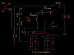
Here's a schematic:

PIR-powerup.PNG

When motion is detected, the PIR sends a high on the OUT line which turns on transistor, T1, which in turn, turns on transistor T2 and supplies power to the V+ pin on the PICAXE. The program running on the PICAXE immediately puts pin C.5 high which will keep the PICAXE powered up even if the PIR no longer detects motion. Then the PICAXE can check your shelf switch/sensor, light the red leds, etc. Then after some timeout, you can program the PICAXE to shut itself down by putting C.5 low. If while the PICAXE is powered up, more motion is detected, pin C.3 will be high and you can check for that either with an interrupt or just while looping and reset the timeout.

The PIR I'm using only consumes 30-50uA so if the PIR is not constantly detecting motion and if your red lights aren't on all the time, the batteries should last a long time.
 

SAborn

Senior Member
@Hemi345,
Neat idea and very simple, although in your circuit schematic, i would have thought the base of T2 should be pulled high with a resistor to 5v, and no resistor ( R2 ) between T1 collector and T2 base.
 

Hemi345

Senior Member
@SAborn, I thought a BJT didn't need a pulldown/up resistor (unlike, MOSFETs, where you need to pull the gate high or low to keep it from floating) unless you want it to switch off more quickly? I don't think it matters how fast it turns off since it's only supplying power and not any sort of logic.

I simulated it in EveryCircuit as I have it above and put it to work in my project and it works. But here's some screen caps of mine and yours with a 100mA load.

npn-pnp-pair.png

(sorry, don't mean to hijack this thread)
 

MikeAusP

Member
. . . . the movement of my shelf platform can move up and down in a range of 1-5 cms when the belongings are placed on. . . .
With a movement of 1 to 5 cm in the shelf, you should have no trouble at all using two metal strips making contact as input to the PICAXE.

Later you could even sense how heavy the object on the shelf was - make first contact at 1 cm movement, next contact at 2cm movement etc.

For someone who hasn't written a single line of code yet and a looming deadline, the most important design goal needs to be simplicity.
 

manuka

Senior Member
to use a external power such as a power plug how will I connect this to my pic axe?
Simply select a DC plug pak that'll deliver in the 3-5V DC range & insert (+ to + etc) where the battery connections normally go. Most thrift shops have huge stashes of ex cell phone chargers (often Nokia 5V) for a few $ that are ideal for this. Using such a plug pak however means you'll need a nearby mains outlet, which may not of course be available for a high shelf. Alkaline batteries (3 x AA) should initially suit PICAXE projects like yours,especially if energy saving software tweaks are adopted.

But enough of the tedious "what if" & "how can" my good man! You are continually asking questions that self directed learning could readily have answered in a few minutes with a dirt cheap solder-less breadboard & simple coding. Andrew Hornblow's "PICAXE Picasa" approaches mentioned some posts back show the style. Even pre-teens here in NZ use these!

Ahem -have YOU actually done any hands on PICAXE work at all yet ? Have YOU flashed a few LEDs, rustled up sounds, or made ADC readings ? IR (infrared) sending & detecting commands are inbuilt in even the humble 08M - have you explored these? Have you read the esteemed PICAXE manuals? Have you Googled some of the basic issues that arise ?
 

MikeAusP

Member
In Oz, the cheapest and most accessible motion sensor, powered from 4.5 volt is to buy a $10 3xAA powered sensor light from Woolies and use the switched light output as a Picaxe input.

Hmmm . . . if you have too much trouble getting a grasp of software controlled hardware before the deadline, here's a fallback plan.

Disassemble the Woolies light and aim the LEDs so they light up the shelf. Arrange the shelf switch so that the switch opens when items are on the shelf. Wire the switch across the Light sensor (electrically in parallel) and put black tape over the sensor.

Now if someone walks past the shelf when there's something on the shelf, it will be lit up.
 
@MikeAusP

Yes about the 4.5 volt $10 3xAA powered sensor light from woollies I typed that in their website but nothing came up.

By the way Folks has anyone had any problems with making orders from littlebirselectronics?, as iv made an order for a PIR motion sensor on the
12th and it hasn't arrived yet , they said it would arrive 3-5 days. I emailed them and there making up some BS and not emailing
me back.......
 
Hi Folks, thanks for your feedback and contribution

Just another problem iv come across.How am i suppose to connect my PIR motions sensor to my picaxe?
link to PIR sensor type - http://littlebirdelectronics.com/products/digital-infrared-motion-sensor
The PIR motions sensor has a external chord which inputs into the PIR chip and the little plug itself is forked into 1,2,3 which is 1 for D and 2 for VCC 3 for GND or something.
so ye how do i actually connect the PIR motion sensor to the picaxe if their is a chord?, do i just chop off the other end of the chors and solder it onto the picaxe?
 

bpowell

Senior Member
The PIR motions sensor has a external chord which inputs into the PIR chip and the little plug itself is forked into 1,2,3 which is 1 for D and 2 for VCC 3 for GND or something.
so ye how do i actually connect the PIR motion sensor to the picaxe if their is a chord?, do i just chop off the other end of the chors and solder it onto the picaxe?
It depends what kind of breadboard / protoboard solution you're using...you may need to chop the plug off, strip and tin the wires, and then plug them into a breadboard...or solder on a connector that will work for you.

Check the datasheet for your PIR sensor...the GND is GROUND...the same ground you'll use for your PICAXE...the VCC is (most likely, but check your data sheet) 5-Volts DC power (same voltage you'll use for your PICAXE)...the "D" signal is the digital output...again, check your data sheet...you may need to pull it high or low, and then connect it to whatever pin on the PICAXE you're going to use for the input.
 

bpowell

Senior Member
So HenryHens66 (and other Australians on the forum),

I have to ask, and I'm trying not to be rude...is this what normal high-school is like for Australian folks? You indicated in your first post that you're taking a "Design Technology" class...and you've indicated though-out this tread your instructor has said this-or-that, or suggested this-or-that...but you also seem to be at square-1 when it comes to understanding any of the technology you're supposed to be using. Which is okay, believe me...we ALL start at square-1 (well, maybe not Hippy and Dippy...they seem freakishly smart...but the rest of us). Heck, I'm only one-foot onto Square-2!

I'm just curious, because I have this impression that you sat down in class on the first day of the school year, your instructor gave you this big assignment, and you all left...never to return to class until it's time to turn in your finished projects! If this is the case, what are the instructors even for?! They sound more like "Assigners" than "instructors".

For example, here in America...a comparable class would likely teach the fundamentals of the technologies to be employed, electronics, mechanics, some theory, etc...and then, once your "tool box" was full, you'd be given a detailed assignment (such as the one you've undertaken)...but you would be able to use the fundamentals you learned to complete the assignment.

It just seems very odd to me that you're in this class, you have an instructor...and yet, you don't seem to know any of the fundamentals of the project you're trying to complete...It's like being told, "Build a submarine" without knowing a thing about the sea.

As I read this thread, this question has been bugging me, so I'm throwing it out there...and maybe this really is how school works in other countries...and maybe it's a good thing...America has certainly had a decline in science knowledge lately...maybe this "trial by fire" method works...but then again, it really seems like the PICAXE forum is doing this project, and not the student who will be turning it in. So in the end, what is HenryHens66 learning, other than to follow step-by-step directions, cut-and-paste code, and submit as original work?

Once again HenryHens66...this isn't a dig on you at all...it's just an honest question from an ignorant foreigner.
 

Dippy

Moderator
The connection is as bpowell says in #93.
Henry, if you look at the page you linked you will see it says:-
"If anything moves after that period, the 'alarm' pin will go low."
&
"Output level(HIGH):4V"
&
"Output level(LOW):0.4V"

This , apparently, is a 'driven' output so you shouldn't need any pull=up/down resistors like, for example,.and open collector/drain output.
In theory you could directly connect it to a PICAXE pin, though many here would advise a resistor in series (in line) with the signal for safety.

I would strongly suggest you test it first by powering it from 5V and checking the "D" pin1 by putting a multimeter between that pin and ground (GND / 0V). Multimeter set to DC VOLTS of course.
If that is OK then connect to PICAXE and test the signal by using an IF statement in code.

I reckon Henry's tutor/teacher should be giving some 1-to-1 advice here. We don't seem to be progressing much.

In the dim & distant I also remember having horrid projects but, as bpowell says, was taught the basics and just needed a little prompting. Fortunately I had enthusiastic teachers (who actually knew their stuff) and my Dad was an EE.
The post-grad lads I have to guide at work are very much of the cut'n'paste generation - it shows... sadly.
 

hippy

Technical Support
Staff member
I'm just curious, because I have this impression that you sat down in class on the first day of the school year, your instructor gave you this big assignment, and you all left...never to return to class until it's time to turn in your finished projects! If this is the case, what are the instructors even for?! They sound more like "Assigners" than "instructors".
It could well be that it was effectively an assignment; "This year we will each make a project; you decide what you want to do, and we will mark whatever you come up with". It could be that the ambitiousness of the project has been left to the students to decide upon.

"Trial by fire", yes, but the students get to choose their fire. It allows students to work at the level they are comfortable with but does run the risk that some students may choose over ambitious projects or find that, what seems to be a simple project, is more involved than anticipated.

Any apparent lack of guidance or help from the teacher could be that this is not a specific PICAXE course, perhaps more a design course, and the teacher has taken the approach of 'if you want to fit a PICAXE in it then that's fine by me'.

Only HenryHens66 can give us the full background story.
 

westaust55

Moderator
@henry,
A photo posted showing exactly the chord/cable as supplied with your PIR would be useful.
The website photos all show a 3-pin header connection.

You will have 3 lines as
Vcc (it is rated 3 to 5 V)
Ground / 0V
Signal - to be wired to a PICAXE input.
 

manuka

Senior Member
bpowell: "If youth only knew, if age were only able".

Few teachers here in Aus/NZ are hands off! I put in a solid 40 years at the e-tech. educational chalkface & relate that "down under" instructors (myself included) often may end up vitually doing the students work for them, especially if emerging technologies are employed that neither initially are that familiar with.

Although such master/slave approaches were perhaps once inevitable when resources were basic/standardised & knowledge was elusive, the modern issue relates to students often being better informed (but far less skilled) than their educators. Many older instructors have yet to master even a basic smart phone,spending work hours instead wrestling with classroom,educational,pastoral, sporting, admin., curriculum & resource issues- and marking!

Few experienced e-tech. educators have the time & energy to investigate emerging micro approaches (DigiSpark or RPi etc). I still encounter "chalkies" who are so blinkered with reliable 741/555 circuitry that they have yet to consider simpler PICAXE approaches.
 

bpowell

Senior Member
Hippy, Dippy, & Manuka,

Thanks for the replies. I didn't think teachers were so "hands-off"...I have a feeling like Hippy said...it might have been a case of, "You want to use a what? PicAXE? Well, okay..." kind of situation.

I've never been to a micro-controller programming class before, so everything I've learned has been from reading manuals / datasheets, or picking apart code I've found posted here and elsewhere...so it certainly IS a valid learning technique...but I've never tried to do it with a deadline looming.

I will continue observing and helping where I can.
 

SAborn

Senior Member
From the kids i have helped out with for school projects over time, it has been projects the student has elected to build, so i dont think the teacher or student can be both expected to fully understand the requirements on all electronic levels.
Often part of the assignment is for the student to source help and information, and is why i suspect Harry is here on the forum asking questions.

He may have bitten off more than he is capable of knowledge wise, but the way i see it, that is where some of us here fit in to also help direct him to complete his project, i dont see it as doing his project for him, more so helping him learn what is involved in taking a concept and designing it to a functional level.

The first indication that Harry knows little about picaxe, was some posts back when i had suggested using a load cell and the interface board i offered to build, would require working with 16 bit data (a word value) and that became too hard to do, as most here would see a word value as no obstacle, Harry did.

The question i ask is do we see this Kid not complete his project, simply because he has bitten of more than his knowledge of electronics allows in the given time span, or do we partly help design and complete his project, and hope that some guidance leads on to a future interest in electronics with some knowledge gained along the way.

We all start somewhere, and for me it was in high school 35 years ago, i took a electronics subject in science, and today im still learning, although i have had a lot of fun learning along the way, the thing with electronics is we never stop learning, it continuously keeps evolving.

Personally i think Harry is totally lost with his project, other than perhaps managing some code to flash a few leds, so do we all give up or do we help out with a circuit design and write some code to help complete his project.

If nothing else he is here on the forum trying to find information for his project, and one would expect he also has 10 other assignments from other subjects thats due in a matter of days, as well as sport, family commitments , and general life, so this project easily gets less priority and time to be work on.
 

bpowell

Senior Member
SAborn,

Thanks for the reply.

To be clear: Whether to help HenryHens66 or not is not what I was asking...I have no problem with helping as I can, and anybody else helping...this is a great forum, filled with very helpful people...I know I've benefited from it! I'm always happy to "pay it forward".

I was just honestly asking if this is a normal educational technique in Australia...I don't have any personal experience in the matter, so threw the question out there.

I'm glad HenryHens66 thought of a PICAXE in the first place...hopefully playing around with the code and LEDs will give him the "bug" to play some more!
 
Only HenryHens66 can give us the full background story...
@bpowell

Yes that is true, the thing in Australia is that we have a subject called design technology not a subject specifically for programming picaxes and the all of the above electronics.
The thing in Australia across the whole state students pick subjects in interest them to pursue into being countered towards their ATAR a final mark for all 6 subjects which is a varies complication of combining class test with assignment etc... with a final big exam THE HSC (they call in Australia) in which you get scaled and all that stuff in which you get a final digit for as your HSC ATAR competing against all other school across the states. The highest you can get is 95.95 in which you used this so called ATAR to get into university's across the state.

So ye back to the subject of DT , the format of this subject is once you hit year 12 , for america it should be your senior years or last year at school before goign to university and etc... For year 12 you pick a project you wanted to undertake to design for you MDP- major project design. So you choose anything any design you want to undertake and pursue it easy right nope... the first thing i came up was with a wall which illuminates just like a traditional light by touching the wall itself ,and there would be a detachable canvas on it so that you can change the scheme of your walls in your room. The whole design was to counter the traditional lights at home and bring a alternate view of how light can be projected ,and to bring life to young peoples life as when you are a child you do anything. Drawing is the most imaginative thing you do apart from exploring. So ye one of my teachers says that design was rubbish so i cried for a few weeks , no just kidding.. the teacher just beat the idea out of my brain. So me and my teacher negotiated and came up with a tweaked idea upon my original design instead of a wall it would be a shelf component and which for the placement of belongings KWP- key wallet phone. Which was still very early on the process and not nearly have looked like the shelf iv ended up with today. Anyway so I investigated into this until later on ,one of our three DT teachers left and abandoned the department as she got pregnant. This is when , which will finally answer your questions and the mystery behind why i used the picaxe. So a new teacher came in he was specialised in the industrial electronics of design or something. He was referenced to me by my teacher as everyone else was so he looked at every ones design. So when he came across my design of the plain boring shelf he suggested to use the picaxe and all the heebba jeebba leds sensors to be incorporated into my design and bring life to my shelf, so that its interactive. So that is covered a design brief and had purpose a need of aiding people with bad memories, or to simply change human bad behaviour to having your important belongs in one place. So ye sorry about the long article i have written as it has come to my attention allot of you are overseas and don't get the concept in Australia of how the education scheme is organised here.

PS. sorry i havnt been posting recently in reply to posts, as iv had no access to internet for a couple days and just recently been organising my evening display for my DT project at school along with another project for ART.

but thank guys for all the feedback more than 100! posts already, of ranting and stuff..., i know that i seem like iv been asking to many questions its just i started at 0 with this project using the picaxe and didn't have the luxury's of class where they get tought the basic and stuff like what Americans students get provided by school these days.
so ye thanks once again and hope to talk soon to you guys! :)
 
Last edited:

bpowell

Senior Member
HenryHens66: Thanks for the great description of how your classes are structured. It certainly sounds like a challenging program, but as I said in my earlier post...those kind of challenges are just what people can use to learn from! Good luck to you!
 
789456123.JPG

Hey Folks

Its been a while aye, just felt like uploading a picture of my finished product (HSC MDP - major project), in return for thanking you all for your contribution.
Very grateful that you folks took the time in suggesting and guiding me into the introduction of varied electronics, in which i could use
to help suit my project.

Cheers

Henry
 

manuka

Senior Member
Henry: OK! Now we can see the finished product (which doesn't look much like I'd imagined!), can you perhaps outline just how it works? I spot the PIR - how sensitive is it? Does the LCD have just one message - "Touch shelf to cancel" ?

Why all the bumps, curves & blue patches - surely things will slip off these, or is it just a quirk of the lighting ? How is it all finally powered? Current drain? Size ? Stan.
 

SAborn

Senior Member
I did assist Henry with some of the electronics and provided him with a load cell circuit that the picaxe reads the shelf weight from.
A 7kg load cell was used, and a IR sensor (round button below the display)

The Ir sensor triggers the system, and the current shelf weight is recorded, then the picaxe looks for weight added or weight subtracted, and/or weight change but no addition or subtraction.

The LCD scrolls a message to remind you to use the shelf, or to touch the shelf to cancel the operation (weight change but no addition or subtraction.)
Once the shelf detects a change in weight the message changes to something like "Welcome home" or "Have a nice day" depending if weight was added or removed.

When activated it chirps a couple of times to attract your attention, and the blue leds under the shelf flash, after a weight change it chirps again to indicate its recorded the weight change and the leds turn off.
The system has a time out of about 20 seconds that is controlled by the time delay in the IR sensor, once triggered it stays active until the IR sensor times out and can not be reactivated until the time out has occurred.
It can be cancelled within the time out by touching the shelf, but not reactivated until the time out has occurred.

Im sure several things have changed since my involvement, and i only assisted to help get some of the fundamentals working.

I am guessing the shelf shape was for 2 reasons, one to add some bling to the look and make it a little more interesting, and two to help keep the weight back over the load cell and not all the weight out on the edge of the shelf.

The last i knew it was being powered from a mains plug pack, or at least during testing it was.

This is the first time i have seen the final result too, and over all i think Henry has done a excellent job of bringing the idea together, considering the short time he had in the end to complete it.

WELL DONE!
 
Top