Please read, need urgent help for school project!

boriz

Senior Member
"Please read, need urgent help for school project!"

No information in title. Might as well say 'please help' like many before.

In future, please make title relevant to question.

Personally, this sort of vague thread title does not engage me.
 

SAborn

Senior Member
@SAborn
If I buy this PIR sensor, and follow your guides on how to program it from your previous post #36 , it should work right?
The short answer is yes i would expect it to, although i do have several sensors like the ones you have decided on, but have not used them as yet, IMO they are a large ugly, bulky sensor compared to the Mini sensors, and i threw the large ones into the junk box and used the mini sensors as they are small and discreet making them easier to hide neatly.
If you had answered our questions weeks ago then you would have had time to source parts from anywhere, considering you have just had 2 weeks of school holidays one would expect you had time to apply to this project, so remember a lack of planning on your behalf dont make it urgent on our behalf.
Although kids are the same the world over, so i guess nothing changes except dead lines get closer.
 
Pictures?
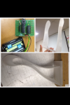
Actually I should had put a picture up earlier but here is one for the moment (see below)

11111111111111111111.PNG

The bottom part of the picture is the side view of my shelf the top right picture is the side panels to seal of the hollow opening of my shelf and the top left picture is my picaxe 20m2 which will sit inside against the back part of the shelf in which will be supported against a wall. Also there will be LEDS inside to illuminate the shelf and sensors under the shelf etc...

(P.S) @Westaust55 , @SAborn here is a picture of my shelf to give you guys some further insight into my product.
 

SAborn

Senior Member
Your work thus far on the shelf construction looks good, and has a funky appearance to it.
You must remember when prototyping an idea, not everything goes to plan, and there will be some degree of ... suck it and see, we try to give the best information we can in regards to what you give us to work with, although there will be some trial and error testing required to get the electronics functional to a acceptable level for the project.
You need to allow time within you project for this testing and changes where needed, that is why Westy and myself have been a little acid tongued in comments to get you to make decisions and move forward.
We are only here to help advise you, not to design the project for you.
Personally i would have constructed the project around a load cell so the shelf weight could be monitored, but that might be outside the actual intention of the project at your level.

What is the time frame deadline you have to complete this project?
 
Personally i would have constructed the project around a load cell so the shelf weight could be monitored, but that might be outside the actual intention of the project at your level.

What is the time frame deadline you have to complete this project?
May I ask what is a load cell?, also my dead line for my project is by 26 August for Board of studies final markings.
 

SAborn

Senior Member
@SAborn

As I'v decided to buy the PIR sensor for the use of detecting bypasses going pass my shelf, I'm still stuck with what sensor I should use to detect if belongings are placed on the shelf or not, is there any sensors which could do the same function of detecting weight such like the load cell?
If you look closely at the picture I provided in Post #45 , the platform where the belongings are placed can move up and down a few mills from weight being applied to the platform as its heat bent acrylic.
The original idea which my teacher posed was to put a sensor strip along side the end of the platform where when keys and wallet and phone are placed on the shelf platform will moves down three separate sections. If the sensor picks up movement of sections not equalling 3 it will illuminate to warm the by by passer they haven't placed all three belongings onto the shelf. what type of sensor would this be called?
Is there any suggestions to where i could obtain something like that or alternatives i could use to operate the same way?
 
Last edited:

rossko57

Senior Member
The original idea which my teacher posed was to put a sensor strip along side the end of the platform where when keys and wallet and phone are placed on the shelf platform will moves down three separate sections. If the sensor picks up movement of sections not equalling 3 it will illuminate to warm the by by passer they haven't placed all three belongings onto the shelf. what type of sensor would this be called?
A "switch" ? Or am I misunderstanding .... a shelf with three sections that bend under loading? A simple microswitch underneath each section will detect the movement. Wire three "normally open" switches in series, and they will act like one big "normally open" switch i.e. all three shelf sections must bend before the circuit is complete.
 

SAborn

Senior Member
I reality there is no real easy fool proof way other than using some proven hi tech approach, several micro switches will only prove problematic with changes in air temp and expansion and contraction of the acrylic.

As i said before if you had responded sooner we could have given thoughts to methods to try, for example the black foam a IC chip often comes inserted in, has a resistance value that changes as you compress the foam, perhaps you could use such a method, although a lot of trial and error testing is required, and then some tricky programming to make it work.
Another method i have seen is a led facing a LDR and using a sharpened pencil to move between the led and ldr to block some of the light, and changing the resistive value of the ldr, it works but problematic to set up and adjustment.

To me to make it somewhat idot proof i would have used a load cell, the same as any industry design would needing to record weight changes, there is a reason industry use them and its reliabilty.

I was prepared to help you out with a load cell circuit board should you have indicated a intention to go that way, but the window of time has closed in that you wont have time to order a load cell and me produce a circuit board to send you.
For the cost of under $10.00 you could have a load cell from China, and the cost of postage for a interface circuit board from me, then your shelf could weigh its contents down to 1 gram or less, depending on the range of the load cell used.


Do you see why not responding to forum requests can effect your end project results.
 

manuka

Senior Member
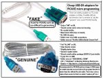
A search of this esteemed Forum would show that cheaper programming cables abound,but perhaps new users may need a direct heads up. Although taming some USB-D9 offerings can be exceedingly frustrating,the "genuine" blue ones shown have long been found totally reliable- I must have bought crates of them over the years for educational work, at bulk prices as low as US$2 each.
 

Attachments

Hemi345

Senior Member
You need to look at the Circuit Creator section of this site: http://www.picaxe.com/Circuit-Creator

There's nothing wrong with asking for help, but it's my opinion that if you cannot take the initiative to research your options and the PICAXE commands needed to exploit them, you might as well turn in your project with SAborn, WestAust55, and other fine PICAXE forum members names on it so they get credit for it.
 
@SAborn

Yes I do understand that , its just I didn't have internet to access the forum half way through my school holidays for a period of time. So that's the reason why I had replied late towards the first page of suggestions people posted kindly . In the other case if we did pursuit a load cell about how long will this process of you making circuit board and ordering a load cell would take? , as my project is formally due by 26 August.
 

manuka

Senior Member
Well at least you have 6 weeks in hand. Past calls for help often are as tight as 6 hours before due date...

Rest easy mate. Cheap piezo sound elements can double as poor man's load cells-they'll easily generate enough voltage to flash an LED when flicked! Andrew Hornblow (of NZ "BrightSpark" fame) shows these & many other user friendly approaches at his educational => PICAXE Picasa site -scroll down for "Input Circuits".

You could hardly beat the hardware setup below for simplicity.Pop into Jaycar for their AB-3440 "low profile piezo transducer" & have the whole thing working by sunset -TODAY!
 

Attachments

westaust55

Moderator
As manuka has indicated, a piezo sensor can be used.
If you have nothing to hand (eg the piezo speaker out of an old card), then Littlebird electronics have a range of piezo devices:
http://littlebirdelectronics.com/search?type=product&q=piezo

Then you can read up on some general information about Pizeo devices: http://en.wikipedia.org/wiki/Piezoelectric_sensor.

Many are intended to give a voltage pulse when flexed/impacted (hit) rather than a continuous signal.

Keep in mind that you need a piezo sensor/element and not a buzzer which has other electronics to "drive" the piezo element to generate an audible noise/sound.

Can you explain for readers how much your shelf will deflect/move when a light wallet+keys are placed upon it. Strain type elements do not need a lot of movement but could need an op-amp as an interface whereas other sensors may need significant movement for an appreciable output voltage.
 
Last edited:

SAborn

Senior Member
In the other case if we did pursuit a load cell about how long will this process of you making circuit board and ordering a load cell would take? , as my project is formally due by 26 August.
Perhaps my method of using a load cell is over complicating a school project, although some schools i have visited the students are doing some rather advanced design work in electronic projects.

Stans idea of using a piezo for a sensor would well be worth you testing.

To answer your question on time to purchase a load cell and produce a circuit board for it, would all depend on the shipping time from China for the load cell, which is around 3 weeks on average but can be longer or shorter.
I would just need time to etch and assemble the load cell circuit board (its a SMD board) , as its a board i have made previous and the artwork is already done.

Ideally you would use 2 load cells wired in parallel, one each end of the shelf to prevent sideways twisting of the cells, although with some design care in mounting, a single cell could be used. (load cells dont like sideways loading)

The cheap cells from China are not usually temperature compensated so some thermal drift will result over time, this is not usually a problem and can be allowed for in program.
How i think you might use a load cell is when the IR sensor is triggered, a shelf weight would be read by the picaxe and stored, then its just a matter of monitoring the shelf weight with further readings to see if weight is removed or added to the shelf from the stored weigh.
This way the thermal drift would not effect the operation as the stored weigh is reset every time the IR sensor is triggered.
I doubt you would need to actually display the weight, only use it to see if the shelf weight has changed within the given time period allowed.

What will power this shelf circuit, batteries, plug pack, and at what voltage, because a regulated smooth constant 5v supply is required for load cell use, changes in supply voltage will effect the cell readings (flat batteries etc)

How good are your programming skills and your ability to construct a circuit with soldering etc.

Please note... i have no intention of doing your project for you, my advice and assistance is only intended to help you establish a direction and a method for you to advance forward with your project.
If you choose to go with a load cell i will assist with a circuit board to read the cell/s, and a basic picaxe program example to read in 20 bits of data from the cell, of which 16 bits is used in program, so if you are able to work with 16 bits of data as a weight measurement and think you can code that into your project its an option you might like to consider.
If it sounds to be to complicated for your ability then you might best look to other methods.
 
You could hardly beat the hardware setup below for simplicity.Pop into Jaycar for their AB-3440 "low profile piezo transducer" & have the whole thing working by sunset -TODAY!
Ahh that simplifies everything instead using a load cell, thank you.
There is a question so the AB-3440 from jay car , does the sensor work by for example (@westaust55 this will answer your questions), the movement of my shelf platform can move up and down in a range of 1-5 cms when the belongings are placed on.
So for the link you provided -http://www.jaycar.com.au/productView.asp?ID=AB3440
how does this actually work , do i just place it under the platform shelf hooking up to the picaxe so when the shelf platform bends and applies pressure on the piezo it reads it through some elctric charge?
and what's the difference between this piezo from littlebirdselec -http://littlebirdelectronics.com/products/piezo-element than the one from jaycar
As i see form through the image ones encase and one not.
Lastly as i am most likely going to go buy one of these piezo sensors from jay car soon ,how will i program this through the picaxe programmer or flowchart for the m2 gen, and is there a link or a guide on how to program this piezo sensor?
 
Last edited:
If it sounds to be to complicated for your ability then you might best look to other methods.
I agree this is much to complicated and my ability to apply to this would be too time consuming or generally i would probably be clueless on how to work with it, but thanks for your time and effort into putting so much information and suggestions towards the path into using the load cell sensor. :)
 

MikeAusP

Member
. . . . the movement of my shelf platform can move up and down in a range of 1-5 cms when the belongings are placed on. . . . .
Then why would anyone consider ANYTHING more complex than a microswitch ????

Imagine how many posts would have been unnecessary if this basic information had been provided earlier on ?
 

lewisg

Senior Member
Then why would anyone consider ANYTHING more complex than a microswitch ????

Imagine how many posts would have been unnecessary if this basic information had been provided earlier on ?
To me it seems it was, in the 1st post:

Hi, I'm a High school student...

The sensor sandwiching the ends of platform of the shelf allows the picaxe to know if anything is placed onto the platform of the shelf as the weight from the belongings push the platform down to hit contact with the sensor.
To me that sounds like a microswitch and I assumed that was where this was headed. I'd likely go with a light sensor that has to be covered with an object so I wouldn't have to spend time with the mechanics of a moving platform.
 

westaust55

Moderator
... the movement of my shelf platform can move up and down in a range of 1-5 cms when the belongings are placed on.
So for the link you provided -http://www.jaycar.com.au/productView.asp?ID=AB3440
how does this actually work , do i just place it under the platform shelf hooking up to the picaxe so when the shelf platform bends and applies pressure on the piezo it reads it through some electric charge?
and what's the difference between this piezo from littlebirdselec -http://littlebirdelectronics.com/products/piezo-element than the one from jaycar
As i see form through the image ones encase and one not.
Lastly as i am most likely going to go buy one of these piezo sensors from jaycar soon
The bare piezo sensor would likely be a better option than the one encapsulated in plastic.
You would need to bond the piezo sensor to the underside of the flexing shelf and use it like a form of strain gauge. The more movement as items are added or removed form the shelf results in a change in voltage.
This is where you need to investigate for yourself rather than rely 100% on others. I suspect that you may need to use an opamp to increase the range of the voltage as the piezo is flexed.
In reality this is a simple form of "home brew" load cell akin to what SAborn has suggested in parallel. If you are not comfortable with load cells you will still find a home brew circuit based on a piezo is too complicated/difficult for you as well.

That said, manuka who proposed the piezo concept at post 56 with links to the picasa website may have some further information on voltage output and duration if he continues to read this thread. Otherwise it is test/experiment yourself.
As a starting point, see the picasa website here; https://picasaweb.google.com/picaxe/InputCircuits#5633823812413927298 and there is a link at the bottom that takes you to the schematic diagram - that needs some extra components (transistor, resistors etc).
see also this picasa webpage https://picasaweb.google.com/picaxe/InputCircuits#5135515332897301218
that has a direct connected piezo
While the picasa website gives photos and schematic Andrew and fireds there do not give you full working code. That is for the school children to work out for themselves maybe with teacher assistance.

You might also read this PICAXE forum thread on using a piezo sensor as a movement detector.
http://www.picaxeforum.co.uk/showthread.php?10639-motion-vibration-sensor-with-piezo.
Notice how there is reference to testing the output of the piezo just as I have suggested above. Also the possible need for amplification (an op-amp).

A theme here is that you should be doing some of our own research and not just asking question on how to do each and every step of you project.

,how will i program this through the picaxe programmer or flowchart for the M2 gen, and is there a link or a guide on how to program this piezo sensor?
You seem to have this concept of programming the sensors. While a few may/do need some programming or calibration, may such as switches, PIR's, etc do not need programming themselves.
What YOU do need to do is write a section of program for your PICAXE to accept the signals whether digital or analogue, scale or modify the value stored in a variable when the sensor is "read" and make decisions based on the value.

EDIT:
I suspect that for any simple circuit the piezo will detect vibration/movement while it occurs but you will not know some time later if the shelf has more or less weight without more complex circuitry such as a resistance bridge using a strain gauge or load cell.
 
Last edited:

SAborn

Senior Member
I agree this is much to complicated and my ability to apply to this would be too time consuming or generally i would probably be clueless on how to work with it
Well at least you are honest about your ability, other than using a micro switch with a simple on/off action, you will be working with some form of data weather you like it or not, regardless if its 8 bit or 16 bit data ( 8 bit = 0 to 255) (16 bit = 0 to 65535)

You might be best to look towards using a simple micro switch, as Westy says you will likly need an opamp to work with the piezo method and that can be a daunting task if you have no understanding of opamps.

Another thought might be to use "Touch" as its included in the 20m2, and your shelf being acrylic should work with a metal strip attached to the underside for the touch sensor.

I am not convinced a micro switch would work so well for light objects like a door key, unless you attach a house brick to your key ring.

Good luck with what ever method you choose and i hope your project works well.
 
Another thought might be to use "Touch" as its included in the 20m2, and your shelf being acrylic should work with a metal strip attached to the underside for the touch sensor.
What is this opamp sorry i dont understand, and also for the command "Touch" could you still use that for the piezo or is different? Back to something simpler you said attaching a strip underneath the platform shelf as is bends in contact with some sort of touch sensor. where can i obtain this ?
 

westaust55

Moderator
What is this opamp sorry i dont understand
@henry,

you really must learn to try and search for yourself to find some things out.
Google and forum searching are your fields.

As a start: http://en.wikipedia.org/wiki/Operational_amplifier
Then Google with the term "op-amp" which gets about 12 Million hits.

also for the command "Touch"
see: http://www.picaxe.com/BASIC-Commands/Analogue-InputOutput/touch/
Touch uses a capacitive effect. nominally between a persons finger and a metal contact wired to a PICAXE input.
SAborn is suggesting two copper strips in parallel that move closer together as the shelf flexes/moves and changes the capacitive value.
There has been some past threads where others have experimented with this. try a forum search using the search box at the top right of the forum pages.

We can give you lots of ideas (I stress ideas) but YOU should be doing some research and experiments to determine what and how to build your project with.
 

SAborn

Senior Member
SAborn is suggesting two copper strips in parallel that move closer together as the shelf flexes/moves and changes the capacitive value.
Actually i had not thought of that, i was simply referring to having an area of the shelf as a touch sensor / switch, as when an object is placed on the shelf it would be easy enough to touch an area to indicate that you had placed something on the shelf, most times you only need to be within a few mm of the touch sensor to activate it.

It works just like a button you would press, but in the case of touch, you only need to wipe your finger over the sensor.

The basic thought was an IR sensor to detect a person present, then whatever you intend to attract their attention, flashing leds, beepers, robotic arms to slap them in the face or whatever, then to deactivate the attention seeking action the person would need to touch the shelf or an area of the shelf, in many cases that could well be while placing an object on the shelf.

Its just another idea, as Westy says its up to you to reasearch the ideas to see if they are within your ability, if something seems workable then there is many here that can help you, but you must show some basic involvement to start with, or its just us guys doing your project for you.


Try this.....
connect a length (say 300mm) of plastic coated wire (any size) to pin B.0 (leg 18 of the 20m2 picaxe) and load this test program below into the picaxe, after the download it should open a debug screen on the computer, now watch variable b0 (top of the list) as you move your finger towards the wire, the value in b0 should change.
If that worked you should be able to see that you could make a switch out of it by simply looking for a increase or decrease in the value of b0 within your program.

Code:
#picaxe20m2 

Main:

touch B.0, b0

pause 100

debug

goto main
The 20m2 has 8 touch inputs so you could have several touch areas if required, each one wired to a different input.
You could have Bob, Jane, Mary, Peter, and Paul, sections of the shelf if you wanted, all with their own touch switch, or several touch areas all working as one switch.
 

ValueAdd

Senior Member
Then why would anyone consider ANYTHING more complex than a microswitch ????

Imagine how many posts would have been unnecessary if this basic information had been provided earlier on ?
When you think the OP wanted IR sensors in post 1 and 40 posts later (post 41) we almost there but the OP still wants someone to Rubberstamp what has already been suggested.


As rossko57 picked up from post #49 in his post #50 post there is reference to the shelf having 3 sections.
The original idea which my teacher posed was to put a sensor strip along side the end of the platform where when keys and wallet and phone are placed on the shelf platform will moves down three separate sections.
The lower of the 3 images in the attachment at post 45 does not clearly indicate to me where the 3 sections come into play.

The OP is out of his depth (which he acknowledges), the guys here are typing to help but there is a lack of clear definition for the project, lack of decisions and the whole is getting way too technical.
It is the OP's school project but seeming unwilling to search and seeking help at every micro-step.
If we can get a clear idea of how these 3 sections come into play and what the OP and his teacher had in mind then yes, maybe 3 micro-switches can suffice.
 
@SAborn

Ok, thats interesting. So for this copper wire acting as the touch sensor does it only react to the touch from a finger or can it react for example if i put the wire under the platform of the shelf and when pressure is added onto the shelf it will bend downwards and cause the wire to be squished in between the bottom of the shelf platform with the bottom of the inside shelf. If this works then i don't think it is necessary to use a piezo then?
Just to recap the process of my shelf-
Person walk into hall way of house
walks past shelf (IR sensor detects movement) and detects no applied pressure from the copper wire as the platform of the shelf didn't bend down to apply pressure on it
Picaxe picks up this starts to illuminate the Red LEDs inside shelf.
Person notices and put belongings on shelf
Copper wire now has applied pressure on it as the platform is sandwiching with the bottom of the inside shelf and LEDs fade out OR person touches neat wire design on the side and shuts the LEDS.
And then when leaving Vise versa with if IR sensor detecting and shelf doesn't leave contact with copper wire..... etc...
 

SAborn

Senior Member
or can it react for example if i put the wire under the platform of the shelf and when pressure is added onto the shelf it will bend downwards and cause the wire to be squished in between the bottom of the shelf platform with the bottom of the inside shelf.
No it dont work like that, it responds to somebody touching the area of the wire or metal plate used as a touch sensor, it will even work through the shelf.
You really must do some reading and check out how things work yourself.
 

rossko57

Senior Member
Just to recap the process of my shelf-
Excellent, it could be worth splitting it into tasks;

Light up the shelf - is that done now? You can write a simple test program to flash your LEDs to prove that part works.

Detect somebody passing shelf - is that done now, you have a PIR that works with picaxe? You can write a simple test program to
use the PIR output to turn on the LEDs to prove it works, and see if the PIR coverage is what you hoped for.

Detect items on shelf - this isn't clear yet. Do you need to detect just "something" - or three different somethings? Is the shelf in three sections bending independantly, or just one. There's not yet enough info to see if you want/need three sensing areas or a single sensor that only works when all three sections are occupied.

I'm not sure you even need to detect shelf occupied. If someone comes in, the shelf may or may not be occupied or partly occupied. Either way, don't you want to flash the lights to remind them to put keys/wallet/phone on the shelf? If someone goes out, the shelf may or may not be fully or partly occupied already. Wouldn't you flash the lights to remind them to pick up? When would you not want to flash lights as someone passes?
 
it will even work through the shelf.
How does that actually work, is it like a makey makey where it sends an electric pulse through the object that its connected to, so when you touch the object it reacts to whatever you program it to do for instance, touching the shelf is to turn of the LEDS illuminating in the shelf.
 
Detect items on shelf - this isn't clear yet. Do you need to detect just "something" - or three different somethings? Is the shelf in three sections bending independantly, or just one.
I thought about actually changing the process to a much simpler format, so that i could cut out the complication of the three section sensor thing for the shelf. AS it was just getting out hand on my ability to pursue it.

NEW Process-
Owner enters home
Walks past shelf
PIR sensor picks up movment, sends signal to picaxe to light up LED regardless if objects are placed or not placed on the shelf.
situation 1 - owner puts belongings on shelf and touches the shelf to stop the illuminating LEDS
situation 2 - owner has already put objects on shelf touches the shelf and shuts the LEDS from illuminating.
same Vise versa when leaving

I thought this process would be much easier , from grabbing some ideas at @SAborns Post 67#.
 

westaust55

Moderator
A “touch” wire/sensor system should be easy to implement.
Read about the TOUCH command in the PICAXE manual 2.

I recall that the intent is not to actually touch the sensor element/contact but in effect bring one’s finger close. In that case, a thin layer of plastic over the wire/sensor element so insulated wire or a layer of cling wrap (eg Gladwrap or similar) over a flat contact sensor may suffice.

If you do a search on this PICAXE forum, others have previously posted some code to calibrate the touch sensor inputs automatically when the program starts.
 

SD70M

Senior Member
I recall that the intent is not to actually touch the sensor element/contact but in effect bring one’s finger close.
That's correct, direct contact can damage the picaxe chip apparently.

Adding to what henry has now decided, why not add a timer to the LEDs being lit up, so if the PIR senses movement, and the LEDs light up, if no-one touches the shelf, for say 20 seconds, the LEDs go out. That will save battery life and reset for the next use.

Angie
 
OK thanks very much @westaust55 and @SD70M,

I have several quetions on some technical difficulties and theoretical problems which im stumped on.

1..I have come across a diffuctly in assembling one resistor on my picaxe which the assembling notes says
" Input 0 can optionally pulled high (use 10k resistor in position RPU) or pulled low (use the resistor in position RPD). only fit one of the two positions"
I dont really know where to solder the resistor to on my picaxe the placement is suppose to be either IN (RPU) OR (RPD).

2. Question on how many LEDS can one output on a picaxe 20m2 can handle? As i want to maxmise the illumination look of my shelf. Is there a limit to how many LEDS can be linked to one input/output on my picaxe 20m2?

3. From discussing with my teacher i have brung back the sensor of the shelf detecting if items are placed on it. The four main mechanism running my shelf are-

NUMBER (1) The shelf detecting sensor of objects being put onto the shelf platform. location fo mechanism Strip of copper is strapped to the bottom of the shelf platform and when weight applied to the shelf it bends down to hit contact with another copper strip located under it to detect belongings are polaced on the shelf. (not sure what type of command this is used the Touch command for contatc of two copper strips?)
NUMBER (2) the insulated copper wire touch switch sensor for switching off the LEDS
NUMBER (3) The PIR motion sensor located under the shelf which detects movement past the shelf
NUMBER (4) The LEDS lighting up

Using Psuedo code , i'v listed four outcomes which the shelf could react to, just to give you a better insight of the process. ( havnt programmed this yet)

IF 1 is ON AND 2 is OFF AND 3 is ON THEN 4 is ON (When someone has walked past shelf and has placed object on shelf but forgot to turn off LED)

IF 1 is OFF AND 2 is OFF AND 3 iS ON THEN 4 is ON ( When someone has walked past forgot to put belongings on shelf LED Illuminate to warn the person)

IF 1 is ON AND 2 is ON AND 3 is ON THEN 4 is OFF ( When someone has walked past shelf has placed belongings on shelf and has turn off LEDs illuminating the shelf) Same when leaving house

IF 1 is OFF and 2 is ON AND 3 is ON Then 4 is OFF ( When someone wants to make their way past shelf eg. to answer door bell or get mail , no need for alerting owner to pick up keys.)

For my programmign sector of my project im struggeling on actually how to write this in programed format so i can simulate this on my picaxe with all the input sensors? , im intending to use either the picaxe editor programmer but most preferably the Picaxe Flow Chart programmer for M2 gen picaxes
 
Last edited:

westaust55

Moderator
I believe you have the AXE118 with 20M2< Maybe you can confirm that.
Based on the AXE118, the answers to your 3 questions are:

1. Input0 Pull-up/down resistor
You need to decide which devices you will connect to the various IO before you can make a decision. The other 7 pins on PortC are ties to ground.
If for example you were going to use a TSOP4838 IR receiver as discussed early in this thread then a pull up would be a good position &#8211; but now you are using a PIR with a driven output this is not essential.
Some options are &#8211;(a) leave out the resistor for now &#8211; having the input floating will not harm the PICAXE (b) fit it as a pull up if you might every have an open collector device connected in future..

2. LEDs on PICAXE IO
The AXE118 board has a ULN2803 8-ChannelDarlington transistor array &#8220;chip&#8221; on the PortB pins. Thus the PICAXE will not directly drive the LED&#8217;s but control the ULN2803 to turn on the outputs. Note that when the ULN2803 outputs are on they are in effect a switch to ground so your LEDs need to be between +5V and the ULN2803 along with a series resistor to control the LED current.
The ULN2803 outputs can control up to 600 mA. With only 5 Volts you will struggle to have LEDs in series but you could have several in parallel each with its own resistor to ensure proper current sharing.
Since I anticipate that you will want the LEDs very bright to attract attention you will likely want to design for about 20mA through each LED.

3. Various
I am only answering the last part here for now.
While you could use the flow chart method of programming far more folks here use the text based BASIC programming method. I for one do not use the flow chart method so while it is promoted for schools it may limit the programming help that you receive.
 
Last edited:

rossko57

Senior Member
NUMBER (1) The shelf detecting sensor of objects being put onto the shelf platform. location fo mechanism Strip of copper is strapped to the bottom of the shelf platform and when weight applied to the shelf it bends down to hit contact with another copper strip located under it to detect belongings are polaced on the shelf. (not sure what type of command this is used the Touch command for contatc of two copper strips?)
This is just a "switch". See the Picaxe manuals for how to use switches. This will also help answer your resistor question; you might for example connect one of your strips to ground. The other strip would then either "float" at some undetermined voltage, or when activated be connected to ground. This is connected to your Picaxe input. "Floating" is a Bad Thing so you would use a pull-up resistor to make it be a known high voltage, when it isn't grounded by the switch action.

IF 1 is OFF and 2 is ON AND 3 is ON Then 4 is OFF ( When someone wants to make their way past shelf eg. to answer door bell or get mail , no need for alerting owner to pick up keys.)
You've no sensor for the passerby's intentions here. You cannot tell whether they are going out, or going to answer the doorbell. Or even returning from answering the dorr- you don't even know which way they are going (though it would be possible to find out with more sensors).
You _can_ tell what has happened in the past - did they touch the shelf hours ago? Was something put on the shelf last, or was it all taken off last? I don't think that helps much, but you should have a think about it.

For my programmign sector of my project im struggeling on actually how to write this in programed format so i can simulate this on my picaxe with all the input sensors?
Start simple. Make it flash your LEDs. Then grow it to only flash the LEDs when the PIR is triggered. Treat it as a development process to grow something bit by bit.
 
@Westaust55 & @rossko57

@westaust yes i do have the AXE 118 picaxe-20m project board kit, sorry I didn't clarify that earlier.

Thanks again guys for the info, one more quick question what recommended LEDs do you think I should buy?

As for LEDs my dad has LED strips used for light boxes and signs which i was considering to use ,but i don't think ill be able to use these as the picaxe wont be able to power it due to its needs of an external transformer to run it, I'm not exactly sure i might be wrong tho...

To the case of the standard LEDs which I'm planning to get from Jaycar to use in my project, I'm not exactly sure which specific type of LED i should get i only so far know i need red coloured ones, also for the LEDS I'm using in my shelf how many mm and MCD should the LEDS im using be suitable to illuminate through my acrylic shelf?.
Here's are web link to Jaycars LEDs -
http://www.jaycar.com.au/productResults.aspwhichpage=1&pagesize=10&keywords=&MID=1&SUBCATID=976&SSUBID=687&form=CAT2#1
 

westaust55

Moderator
Sorry but I have no firm idea on what mCd output or spacing you need.

Are you going to drill a series of holes in the rear edge of the shelf to insert the LED's and then run some wires along the back edge?

Thinking of a time when I changed the LED colour in an LCD display to achieve a different background colour. The original was one LED mounted at the edge in a housing and a plastic diffraction layer.
When I used a fairly "ordinary LED that might have been around 100 mCd, I could not tell that the KLED was even on.
I changed to a superbright 18,000 mCd LED and that worked perfectly. Now that was one super bright LED for a 25 x 100 mm area. That might equate to about 25 mm of your shelf length.

You might need to do some tests on an off-cut of your acrylic to determine a good spacing.

As an Australian alternative to JAycar you could try here:
http://www.ledsales.com.au/catalog/index.php

I purchased a fist full of RGB LEDs from them some years ago without problems.
 
Top