One-Wire Devices / Networks

westaust55

Moderator
Programming EPROM memory in 1-Wire devices eg DS2406

As promised, attached is some PICAXE program code to allow one to read the EPROM and Status memory from a DS2406 chip (Dual PIO plus 128bytes of EPROM).

The program firstly reads the EPROM and STATUS memories and displays the contents in the PE F8 terminal window.

I include a check to see if the EPROM memory is totally clear but many may want to delete that.

Next the program writes each byte of data from the PICAXE program1 byte at a time to the DS2406 1-byte scratchpad, checks the 16-bit CRC returns is correct and if so then writes the byte to EPROM memory. If the 16-bit CRC is wrong, the program will try that location one more time before aborting.

The program runs at 8MHz so that PAUSE 1 equates to approx 500microseconds for the typically 480uSec programming pulse.
This is not too crucial but if there is a need to re-write a location (can only make more bits from 1 to 0) the datasheet states that the max cumulative program pulse duration to each EPROM location is 5 milliseconds.

My program as posted only writes data to the first page (32 bytes) of EPROM but is easily modified to write to any location/part of the EPROM.

Also I do not immediately read back the data to check if it is correct. That can be added and another attemp made to write the byte if there are bits = 1 that should be =0 (remember using EPROM you CANNOT change a 0 back to a 1 as with EEPROM).

Once the desired EPROM locations are all written to, the program then displays the new contents of the EPROM memory.

Attached also is a program output as seen on the PE (F8) terminal window.

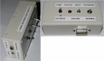
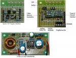
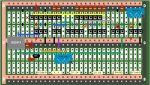
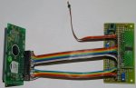
I built up the small circuit for the 12V programming interface from the Maxim datasheets on a piece of protoboard about 30mm x 30mm. The separate 3V to 12V converter is on a separate board about 30mm x 60mm in dimensions.

As built, the PICAXE pin for the programming signal MUST be made high before the 12V supply is connected. This is because PICAXE outputs are low by default which for the circuit puts the 12V supply onto the 1-Wire line to the non-Master device(s)

The programming interface circuit could be left permanently in the 1-Wire network with the 12V supply disconnected but that does introduce a small voltdrop across the FET transistor, which may influence longer 1-Wire networks, so I would suggest removing entirely from the circuit (DPDT toggle switch would do) unless programming a device with EPROM.

Have fun in a PICAXE world :)
 

Attachments

westaust55

Moderator
1-Wire network tests with 100m of CAT-5 cable

Tonight, I did some basic tests on a 1-Wire system using 100 metres of CAT-5 quad twisted pair cable and 5 DS18B20 temperature sensors. The results can be summarised as:

Separately powered network with Vcc (+5V) supplied via one pair to the remote devices.
Works great when the pull-up resistor is reduced to say 2.2 kOhms. At 3.9kOhm and 4.7 kOhm even with just one DS18B20, the 1-Wire network will not function.

Parasitically powered network where the devices all “steal” their power from the data signal line.
Works with from 1 to 5 (max I have available is 5) DS18B20 temperature sensors but
(a) the pull-up resistor must be reduced to 1.5 kOhms
(b) each sensor must be separately given the command to do the temperature conversion
(c) a delay of around 750 milliseconds must be allowed between the Convert_T command and reading the result irrespective of the selected resolution.


The fact that with a separately powered 1-Wire network, I can operate with a higher value of pull-up resistor (2.2 kOhm vs 1/5 kOhm) over 2.5 times the distance (100m vs 40 m) used for previous tests with 2 core screened audio cable does indicate the CAT-5 cable is superior due to lower capacitance.
But the previous test do demonstrate that for short distances you can utilise other cables successfully.
 

westaust55

Moderator
1-Wire Networks and devices Tutorial rev E

Attached is an updated version of the 1-Wire Devices and Network Tutorial.
This includes words and tabulated comparison of various parameters/conditions with longer cable lengths based upon my tests and also includes listings of the various programs written to date demonstrating use of the chips.
 

Attachments

Last edited:

westaust55

Moderator
1-Wire update

Finally, some DS2413 1-wire dual PIO chips arrived yesterday (from Hobby Boards in the US) in TSOP package so I can use them (without an electronic microscope).

The DS2413 is similar to the DS2406 in that both chips have two programmable IO pins that can be used as inputs and/or outputs. That however is where the similarity ends.

The DS2413 does not have on-board EPROM and does not have an activity latch as a convenient way to quickly checking when an IO pin has changed state.

The absence of the activity latch is not a great difficulty, we just need to use a byte variable to hold the previous state of the Status byte.

There are some slight differences in the way in which data is sent to the DS2413, for example, sending the PIO data control byte and then sending the compliment of that byte.

However,
the DS2413 channels A and B can both sink up to 20mA continuously (or 30mA peak/absolute max) whereas
the DS2406 channel A can sink 50mA, but channel B can only sink 8mA.


Should wrap up and post some example PICAXE program code for the DS2413 overnight.
 
Last edited:

westaust55

Moderator
DS2413 DUal PIO example program

Attached is the PICAXE program code example for the DS2413 Dual PIO 1-Wire chip.
The program is different but duplicates the functionality of the dual PIO portion of the DS2406 (code posted previously). Channel A used as an output to flash an LED (or similar) and channel B used as an input and any change in voltage/logic level is indicated.

Attached also is an example of the program output.

Have fun in a PICAXE world :)
 

Attachments

westaust55

Moderator
1-Wire chip carrrier arrangement for ease of identification

Thought that this information may be of use for others.

Many of the 1-Wire chips come in SOIC8 and TSOP6 packages.
These chips are very small so virtually impossible to read the marking without a magnifying glass and certainly insufficient space for application of an adhesive label.

I have a handful of SOIC8 to DIP8 (and some SOIC16 to DIP16) adapter boards.
What I have done is to mount each type I device I have obtained so far in a slightly different format so that just by looking at the carrier arrangement I can determine which chip is which.

Attached is a rough layout guide for the various devices I have been experimenting with to date.

Soon to write some code for the DS2890 256-step digital Pot (courtesy of KTarke) and then onto the larger 16-pin DS2408 8-channel PIO (here KTarke has also sent me one of his SOIC to SIL16 adapter boards with a DS2408 fitted.

Another source of the DS2408 from which I have obtained a few more DS2408 chips is HobbyBoards in the US. Also purchased the DS2413 chips from them. HobbyBoards have very reasonable on postage rates.

Ultimately, I am looking to create an 8-bit DAC based upon a DS2408 since the DS2890 is becoming obsolete

Also to experiment with a DS2408 based LCD interface as an alternative to the 2-wire shift register based version I developed in Nov 2009 and posted here:
http://www.picaxeforum.co.uk/showthread.php?t=13900
The DS2408 has a 9th pin that can by default act as a strobe to "pulse" data into the LCD which takes some of the programming load away from the PICAXE chip. The proof will be in the speed that can be achieved and the size of the program code but will allow an LCD to be located many metres from the PICAXE if this all works well.
 

Attachments

Last edited:

Dippy

Moderator
Hey Westy, how about converting this near-monologue into a few pretty webpages? It'll be easier for people to follow.
 

westaust55

Moderator
Hey Westy, how about converting this near-monologue into a few pretty webpages? It'll be easier for people to follow.
Hi Dippy,

simply put, I could, but I won't.

Reasons:

I see lots of links to external websites that fail in time.
came accross two broken links on another forum tonight when trying to help a member here.

There are only so many hours in a day (to my knowledge, only SAborn has 36 hour days) - I can either support PICAXE or run a website.

I prefer to post the data on this forum and keep it all together for future reference by all PICAXE users in one place.

monologues don't worry me.
My thread on the A55 gLCD was pretty much in that category.
PEBBLE thread was not much different either.

ultimately, I could ask for this thread to be moved to completed projects.
 

Dippy

Moderator
"to my knowledge, only SAborn has 36 hour days"
- judging by your number of posts you're a close second ;)
Maybe 2 - 3 hours per day on Forums?
Plenty of time to write a pukka article.:)
 

Froggs

Member
Hey; what the heck.. still a sterling bit of work. I’m new to this game; but planning to utilise 16+ ds18b20’s across the ranch. So I’ve been keeping up with progress (don’t claim to understand it all… but it’s a grand base), and I’m convinced will save me shed loads of time.. The network will use up to 500m of connections [some of them parallel] so I’m particularly interested in the knitting.. haven’t a clue yet how I’ll power this lot.

What ever it looks like; pretty or otherwise I’m sure many of us have good reason to applaud westaust55+

J
 

ValueAdd

Senior Member
Hey; what the heck.. still a sterling bit of work.
What ever it looks like; pretty or otherwise I’m sure many of us have good reason to applaud westaust55+

J
I whole heartedly agree with Froggs.

This work by westy is great.

I am more a user of technology than an inventive/experimenting type.
I don’t care if I am reading a monologue – in fact that makes it easier to follow if there is less banter and digression amidst the good work.

Some here provide great answers to others problems, some provide great a service with technical information and program examples for all to use, a few just seem to “knock”.

Keep up the good work westy. :)
 

westaust55

Moderator
DS2890 1-Wire 256-step digital pot Program Code

and now, . . . . ( fanfare :D ) . . . continuing my "near monologue" ;)

attached is my example PICAXE program for the DS2890 1-Wire 256-step digital potentiometer.

The DS2890 chips is courtesy of kTarke who also posted some simpler program code a while back.

Findings are that with a nominal 5V (4.97) applied across the potentiometer terminals RH and RL, and am seeing the full voltage range 0 to 4.97 volts at the wiper terminal. This suggests KTarke may need to revisit his earlier experiments where there was a 4V drop relative to the supply voltage which we previously though was due to wiper contact resistance/voltdrop.
I will PM KTarke in case he does not read this.


EDIT: I should also mention that as far as Maxim are concerned, the DS2890 dig pot is obsolete.
I did spot one electronic component reseller who had 100 in stock and there may be other sources with some remaining but it is a device near end of life. Unfortunately with no 1-Wire equivalent replacement.
 

Attachments

Last edited:

ValueAdd

Senior Member
Another great programming example by westy.
I may never have a DS2890 but this is become a very worthwhile library of one-wire information and code for the Picace
 

teddy7

Member
NXP (previously Philips) are the sole allocators of i2c device slave addresses but they do not release a list.

There is a list somewhere out there on the internet. Non NXP which I have downloaded it in the past but cannot quickly locate same.

A problem is that there are only 7 bits for slave address codes = 128 unique so there is much duplication such as all memory devices (EPPROM, RAM and FRAM) using the same slave ID. And within that group of memory, up to 8 addresses can be used. Many modules such as compass, GPS, etc can often allow many different addresses so the prospects for conflicting addresses is far greater and care needs to be take.


Westy, your quite right. And a simple few clicks and one has the HEX Code. I have a chart on my site with the cross from Binary to HEX.
I'd like anyone to tell me if they are all correct. ;) There aren't many yet, but I receive Updates from MAXIM Daily, so I look for
usable devices that could come in handy for I2C and SPI devices.
Cheers,
 
Last edited:

westaust55

Moderator
Hi Teddy,

That lists needs a bit of checking/editing.

For example:
i2cslave %11001100, i2cslow, i2cbyte 'sets up i2c addressing for DS18B20 - Temperature Module 1-Wire $CC

The DS18B20 is in fact a 1-Wire device (as mentioend at the end of the line) and will not work on an i2c bus.
 

teddy7

Member
Hi Teddy,

That lists needs a bit of checking/editing.

For example:
i2cslave %11001100, i2cslow, i2cbyte 'sets up i2c addressing for DS18B20 - Temperature Module 1-Wire $CC

The DS18B20 is in fact a 1-Wire device (as mentioend at the end of the line) and will not work on an i2c bus.


Looks like I shot my own foot off with that one! :(
I have just removed the DS18B20 from the list.
Thanks for the feed-back.
 

westaust55

Moderator
1-Wire Temperature Control Simulation

Recently, Clive Seager from Rev Ed sent me some bits and pieces of 1-Wire hardware than he had in the "bottom drawer" from their own past experiments.

One of the items was an early Dallas Minimalistic Temperature Control Demo board. Dallas Application Note 104 covered the board. From the App Note, the board originally came with PC based software but as I only received the board, I wrote some PICAXE code to use the features on the board.
The board also has a flexible piezoelectric sensor as in input. Using the activity latches on the DS2406 is is easy to ascertain if the piezoelectric sensor was flexed (or even touched) some time later.
Copy of the app note provided in the next post as it is harder than usual to come by.

I also modded the board very slightly to allow the temp sensor and one of the DS2406 chips to be separately powered and the on-board LED's to be powered from the Vcc rail rather than the signal line.

Attached is my demo program using this board.
The program acts as a simulated temp controller driving RED leds if the heater is required and GREEN leds is the cooler is required.
Some temp set-points are established based upon the current temp the temp sensor first detects. If the piezoelectric sensor is touched, a message comes up on the screen.

I will later upload a circuit diagram (both the original by Dallas and my modified circuit) should anyone wish to go down the track of experimenting for themselves.
 

Attachments

Last edited:

westaust55

Moderator
I came across this application note on the Maxim website as App155 entiltled
"1-Wire® Software Resource Guide Device Description"

which amongst other things has a listing of the family number for each type of 1-wire device Dallas/Maxim produce(d).

1-Wire® Software Resource Guide Device Description

A lot of the document is covering TMEX API's which are applicable to direct use of 1-Wire devices with PC's rather than with PICAXE but the mentioned table is a useful reference for those interested in 1-Wire devices.
 
Last edited:

westaust55

Moderator
1-Wire example code corrections

Red faces time today :eek:

Today while experimenting further with 1-Wire devices previously covered I found a couple of errors in the programs previously posted.

At post 14 for Multiple DS18B20 temp sensor example code:
Variable “delay” required to be a word variable and calculation of value for “delay” corrected.

At post 30 for DS2433 EEPROM example code:
line 185 had the sequence for the EEPROM address reversed.
OWOUT OW_Net, %1000, ($55, TA2_Back, TA1_Back, ES_Reg)
Should be:
OWOUT OW_Net, %1000, ($55, TA1_Back, TA2_Back, ES_Reg)

I have uploaded new versions of example program code at each of the original posts so that folks coming along later have the corrected code rather than finding the earlier buggy version and having problems.
 
Last edited:

westaust55

Moderator
1-Wire Network - a network base module

Over recent days I have assembled some small boards into a single box as a form as 1-Wire base module to provide a platform for extension to additional boxes for experimentation. The 1-Wire network will use simple spare audio type cables (ex PC audio apps) for the short experimental circuits.

The attached photos give an idea on what I have put together.
The box includes:
- the logic board to control the 12 Vdc programming pulses for EPROM in ds2406 chips,
- a converter to step 3 Vdc to to 12 Vdc,
- a board with an on-board DS2406 and DS2433 and socket for connection of DS18B20
- and LED which is driven by the DS2406 and a switch which is an input for the DS2406.
- A Normal/Programming selector switch which disconnects the DS2433 and DS18B20 from the 1 Wire Network as well as some other switching to bring the 12 Vdc into play for EPROM programming.

Note that the DS2433 EEPROMs does not need a 12 Vdc programming pulse.
 

Attachments

Last edited:

ValueAdd

Senior Member
Hi westy,

looks good.


Any chance of some schematics for us mortal types ?

This thead seems to be getting plenty of viewers, even if little in the way of responses/acknowledgement/interest shown by the readers.
 

graynomad

Senior Member
@westy
Thought you might be interested in this
http://www.hobby-boards.com
They have a range of networkable 1-wire devices. I doubt you'll learn much (although they do mention wire lenghts somewhere) but it's always interesting to see what others are doing in a similar field.
 

westaust55

Moderator
Thanks Greynomad.

Good to see that some are reading along on my thread, as Valueadd mentions (twice :) ) above.

Had come across hobbyboards myself back at post 38 after the initial DS2413 Dual PIO chips I ordered from Honk Kong arrived in an unusable (for me) micro package format. Hobby boards do have quite good postage rates and fast delivery (about a week US to Aust by normal mail).

Still a few more chips to experiment with. Was originally supposed to be working away this week :eek: but that has been delayed for the moment :cool: .


@VA, yes I might ultimately upload some schematics. Need to draw up properly. Only saved as PEBBLE layouts for some boards at the moment.
 
Last edited:

westaust55

Moderator
1-Wire multi device (DS18B20 DS2406 & DS2433) demo program

Attached is some code that provides a demonstration of my 1-Wire Network base Module.

It assumes that a network search has already been done using the separate program previously posted early in this thread.

This program checks the list for the DS2406, DS18B20 and DS2433 and if the exist in the PICAXE EEPROM list then executes the program reading messages out of EPROM/EEPROM, displaying the temp at regular intervals, flashing the LED and monitoring the switch for a change of state.

Obviously more that can be done here even to verify that the chips are still connected even if they are in the PICAXE EPROM list if one desired. But already way past the size limit to upload as a .bas file on the forum.

Program is provided as a .txt file due to forum size limitation for .bas file type.
Can still be loaded directly in with the P.E. by setting the file type to ALL.

Also provided is a sample output from the program.
The welcome message is stored in the DS2406 EPROM and the part number plus brief text descriptions (for the list of devices) are stored in the DS2433 EEPROM.
 

Attachments

graynomad

Senior Member
Yep I'm interested in reading although I don't have much to input, also we're in the middle of nowhere mostly with no comms (heading your way actually, into WA) so I don't like to start something I can't respond to.
 

westaust55

Moderator
The attached sheets correspond to the program in post 66.

One sheet shows the variable usage as some variable have multiple functions.
The lines with blue shading are fixed. the lines with green shading are free for other uses/program expansion.

The second sheet just shows the data I have put in the DS2406 EEPROM as a welcome message and 1-Wire device descriptions I saved into the DS2433 EEPROM - still some spare space in the EEPROM.

Previous program examples in this thread cover writing to the EEPROM and EPROM.
 

Attachments

westaust55

Moderator
DS2408 8-Channel PIO - using all channels as outputs

I have now started some experiments with a DS2408 8-channel PIO chip.

Attached is a first example program which utilises all 8 channels as outputs and simply counts in binary from 0 to 255 and back down to 0

Will shortly be expanding upon this program adding features such as using 4 channel as outputs and 4 channels as inputs.
 

Attachments

westaust55

Moderator
DS2408 1-Wire 8-channel chip proto-board details

AS part of my programming experiments with the DS2408 1-Wire 8-channel PIO chip, I built up a small protoboard that has the lower 4 channels permanently driving transistors for LED control.

The upper 4 channels uses a couple of small "piggy-back" boards.
- The first is straight through for using the upper 4 channels as inputs,
- The second has a very compressed transistor circuit to use the upper 4 channels as additional LED drivers.


Reason for using the transistors to drive the LED's is that the DS2408 has a maximum/total chip current rating of 20 mA for the 8 PIO plus the strobe/reset pin.

While a bit rough, the attached diagram and schematic shows how the protoboard is set up. Maybe PEBBLE layouts and DIPTRACE schematics later.

The DS2408 is in a SOIC16 package and was courtesy of KTarke pre-mounted on a small board which I reduced in size and in this instance use as a nominal 19 pin single in line (there are three pin space gaps = 0.3 inch between pins 8 and 9). Have since source some more DS2408's from hobbyboards in the US and will be looking to try a 1-Wire LCD interface later as well.
 

Attachments

westaust55

Moderator
DS2408 example code 2

Attached is a second program based upon the DS2408 1-Wire 8-channel PIO chip.

In this example, the lower 4 bits are used as outputs and the upper 4 bits are used as inputs.
After an initial count up to 15 and down to 0, the input on bit/channel 4 is used as a flash rate selector where the bits 0 and 1 drive LEDs which alternately flash on and off.
the switches on the upper three channels are effectively treated as exclusive switches where only one at a time has the corresponding input high. If two or three switches are high only the most significant bit is considered. The three switches are used to set the outputs on channels 2 and 3 in four possible states corresponding to the switch "weighting".

The program demonstrates the use of the channel activity latches as a quick way to ascertain if an input has changed state.
 

Attachments

westaust55

Moderator
1-Wire LCD interface

Just built up and tested a 1-Wire based LCD interface.

Uses a DS2408 8-channel PIO for the 8-bit parallel data plus the "E" pin strobe
plus a DS2413 Dual-channel PIO for the RS (data/command) pin control and backlight control

Speed wise, relatively slow but it does work.
For comparison, an earlier 8-bit shift register (See here) based device achieve speeds of:
bit bashed code at 4MHz clock was 65 msec per character
X1/X2 SHIFTOUT command at 4MHz gave 7.6 msec per character

The 1-Wire interface at 4MHz gave 68 msec per character.

While slow, it still worthwhile for remote displays on the same 1-wire circuit as other 1-wire devices.
For example: to know the temperature in the room you are in which may not be the room where the central controller is located.

Code is attached here.
Board layout and some photos in next post
 

Attachments

Last edited:

westaust55

Moderator
1-Wire LCD interface

Here is a composite with some photos of the interface module
- bare base board
- with DS2408 adapter and DS2413 adapter fitted
- connected to an LCD

and yes, I have not cleaned the solder flux from solder points
 

Attachments

westaust55

Moderator
DS2417 RTC program update

Since no-one took up my earlier challenge (back at post 39) , I have written some code for the DS2417 RTC chip to convert the 32-bit (4 byte) time from a count in seconds since EPOC time (for this program = midnight 1/1/1970) to the the date and time.

The actual PICAXE program code has been posted back at post 39 on page 4 for the original DS2417 post in lieu of the original code (which also happens to have a bug in the date to seconds routine :eek: which is also now fixed in Rev B :) ).

See here for post39: http://www.picaxeforum.co.uk/showthread.php?p=135438
 

hippy

Technical Support
Staff member
Since no-one took up my earlier challenge (back at post 39) , I have written some code for the DS2417 RTC chip to convert the 32-bit (4 byte) time from a count in seconds since EPOC time (for this program = midnight 1/1/1970) to the the date and time.
I knew there was something I started but hadn't finished !

I took the brute force approach; read the 32-bit RTC value, decrement it while incrementing a software RTC until it's zero, then one would increment the software RTC by however many changes necessary to keep it tracking the current 32-bit time. That's a slow start-up but means a simple increment routine to keep it tracking.

For a real 32-bit increment every second counter, started exactly when it was meant to in 1970, you'd have to take into account leap seconds or be 24 seconds slow.
 

Attachments

westaust55

Moderator
you'd have to take into account leap seconds or be 24 seconds slow.
I wonder how many clock showed the correct time at the last leap second in 2008 :eek:

The question might also be, how much longer will there be leap seconds :confused: :
At the 47th meeting of Civil Global Positioning System Service Interface Committee in Fort Worth, Texas, it was announced that a mailed vote would go out on stopping leap seconds.
The plan for the vote is:

* April 2008: ITU Working Party 7A will submit to ITU Study Group 7 project recommendation on stopping leap seconds
* During 2008, Study Group 7 will conduct a vote through mail among member states
* 2011: If 70% of member states agree, the World Radio Conference will approve the recommendation
* 2013: application of leap seconds will stop and UTC will become a continuous time scale if 70% of member states have voted to abolish the leap second, otherwise they will stay the same.
reference (page 8 here):http://www.navcen.uscg.gov/pdf/cgsicMeetings/47/[16] CGSIC47-WL General_md.pdf
 

Attachments

Last edited:

westaust55

Moderator
DS1993 iButton 512byte NV (battery backed) RAM

For those folk interested in the iButton range of 1-Wire devices,

I can confirm that the demo code I presented back in post 30 will also work for the DS1993 iButton (512 byte NV RAM ). My DS1993 sample was courtesy of Revolution Education.

All one needs to do to use the demo code as presented,
is to change the family type references to match the DS1993 part.
replace "DS2433" with "DS1993" and
family code $23 (decimal 35) with $06 (decimal 6)

The DS1993 has the advantage (for RAM at least) of being battery backed (datasheet indicates battery lasting > 10 years) and thus can be mobile yet still retain data in an un-powered state.
 

westaust55

Moderator
I took the brute force approach; read the 32-bit RTC value, decrement it while incrementing a software RTC until it's zero, then one would increment the software RTC by however many changes necessary to keep it tracking the current 32-bit time. That's a slow start-up but means a simple increment routine to keep it tracking.
The Select Structure needs the "Call" statements changed to "Gosub"

Code:
    Select Case rtc.lsw
      Case >= 3600 
        [B][COLOR="Red"]GOSUB[/COLOR][/B] IncHour
        rtc.lsw = rtc.lsw - 3600
      Case >= 60
        [B][COLOR="Red"]GOSUB[/COLOR][/B] IncMin
        rtc.lsw = rtc.lsw - 60
      Else
        Gosub IncSec
        tmp.lsw = 1 : Gosub DecRtc
    End Select
 

westaust55

Moderator
DS1994 512 Byte NV RAM plus RTC-Timer-Counter

Further to my post indicating the demo program code for the DS2433 EEPROM would work with the DS1993 NV RAM,
I can now also confirm that the demo code I presented back in post 30 will also work for the memory component of the DS1994 iButton (512 byte NV RAM plus RTC/Timer/Counter ). My DS1994 sample was courtesy of Revolution Education.

All one needs to do to use the demo code as presented,
is to change the family type references to match the DS1993 part.
replace "DS2433" with "DS1994" and
family code $23 (decimal 35) with $04 (decimal 4)

I have not tried the RTC/Timer/Counter portion of the DS1994 yet ,
but from the datasheet the RTC is very similar to the DS2417 other than an extra byte which holds 1/256ths of a second. Will look into RTC part of the DS1994 soon.
 
Top