One-Wire Devices / Networks

westaust55

Moderator
Based upon the Maxim Application notes including, AN187, AN27 and AN4600,
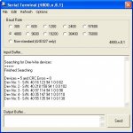
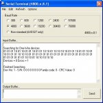
plus other info I am currently writing some PICAXE program code that will search a 1-wire network for connected devices.
This code seems to be working based upon my use of zero and a single DS18B20 at this moment.

There must be a pull up resistor on the PICAXE pin even with no devices present for correct operation.

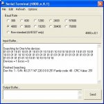
Also added mathematical program code to verify the CRC filed based on Maths as opposed to the more usual 256 byte look-up table which Maxim include in the App Notes which appears to be working based on comparison with a spreadsheet that Maxim make available via AN4600 by looking at the spreadsheet macro. :cool:

Total program memory used so far is 575 bytes, and uses 20 byte variables (b1 as multiple 1-bit flags/values) for search and check but once done, all variables are then available for users ongoing program.


Of some concern however is that rmeldo posted the 8 bytes ROM S/No data for two DS18B20 devices he has about a year ago and that fails my CRC checks and the Maxim spreadsheet for that matter.


While I proceed with code development and fine tuning . . . .
it would be good to see who else has some one-wire devices,
particularly other than DS18B20's (I have a few more DS18B20's and about to try looking for multiple devices to prove that works properly)
and if they can post with a link to their device datasheet AND post the actual ROM serial Nos so that I can enter into my code for further CRC code checking purposes to see if my math based CRC routine is "robust".
 

Attachments

Last edited:

John West

Senior Member
I'm having a very groggy morning today. I opened the thumbnail - then tried to close it by clicking on it's "X" box. Duh. Caffeine......neeeed......
 

hippy

Technical Support
Staff member
This is the code I have for one-wire checksum. Haven't checked it of late ( nor time to do so at the moment ), but it may help ...

How do I check a One-Wire Device Checksum ?

The following code will allow you to confirm that the checksum of a Dallas Semiconductor One-Wire device ( such as the DS18B20 temperature sensor ) is correct. Developed with thanks to Peter H Anderson.

The checksum is an 8-bit CRC, using a polynomial of x8+x5+x4+x+1.

Code:
        SYMBOL DS18B20    = PinNumber

        SYMBOL byte       = b0
        SYMBOL crc        = b1
        SYMBOL bit        = b2
        SYMBOL k          = b3

        SYMBOL POLYNOMIAL = $8C     ' x8+x5+x4+x+1

        READOWSN DS18B20            ' Fills b6 .. b13

        crc = 0

        byte = b6  : GOSUB CrcAdd
        byte = b7  : GOSUB CrcAdd
        byte = b8  : GOSUB CrcAdd
        byte = b9  : GOSUB CrcAdd
        byte = b10 : GOSUB CrcAdd
        byte = b11 : GOSUB CrcAdd
        byte = b12 : GOSUB CrcAdd

        IF crc <> b13 THEN ChecksumFailed

        END

    CrcAdd:
        FOR bit = 0 TO 7
          k = byte ^ crc & 1
          IF k = 0 THEN CrcAdd1
          k = POLYNOMIAL
        CrcAdd1:
          crc = crc / 2 ^ k
          byte = byte / 2
        NEXT
        RETURN
 

westaust55

Moderator
The checksum is an 8-bit CRC, using a polynomial of x8+x5+x4+x+1.
Thats exactly as per the Maxim appnotes and how I have derived my code as well. My code varies a little from yours but is working with the sensors I have.

Tried my search program with any two DS18B20's and works okay.
Added a third DS18B20 and with any third sensor goes into search mode forever. Obviously something wrong in my bit collision and subsequent. Tonights task will be to check for bugs. :rolleyes:

Was looking more for ROM S/N's from other members for various one-wire devices as opposed to program code.
 
Last edited:

hippy

Technical Support
Staff member
Your efforts inspired me to get my one-wire ROM search code out and track down the bug which made me give up on it - that turned out to be the serial number bits are lsb first.

I took a different approach to yourself and used the scratchpad as an array-come-stack so it only uses two byte variables, but 64 in the scratchpad. It's a sort of iterative 'recursive binary tree traversal' which finds one match, then works back down the bits to find where there was a clash, works up and then down again. For example with four serial numbers -

001001
001010
010001
010101

The tree would grow thus, clashes are '?' taken as 0 the first time, replaced with 1 when we back-track then move forward -

0?
_010?
____01 = 001001
____10 = 001010
_10?
___001 = 010001
___101 = 010101

Three more serial numbers for you but all DS18B20 as I don't have any other one-wire devices -

40 10 247 21 1 0 0 52
40 112 203 46 1 0 0 26
40 117 168 209 1 0 0 69
 

westaust55

Moderator
One-Wire network search for devices

Thanks hippy.

Will try your three DS18B20 S/N&#8217;s in the CRC code and MAXIM spreadsheet tonight to ascertin whether that all verify correctly.

The lsbit first was evident from the Maxim App note 187, so I had no problems there.

What I found that the flowchart and C program example using a purely mathematical approach in the MAXIM App Note only has two variables for clashes (Last_Zero and Last_Discrepancy) and thus is limited to a network with about 2 or 3 devices connected.
Hence the program went into oblivion trying to find the other devices and getting &#8220;hung up&#8221; on the first two devices repeating over and over.


Yesterday I changed the collision handling code concept and also went the 64 byte scratchpad for collision detection logging (a bit of overkill but can now handle the absolute max number of one-wire devices) which allows me to track all clashes. Another 8 bytes in scratchpad to hold the current device serial number as it is &#8220;built up&#8221; as each device number is identified bit/byte at a time and CRC verified stored in EEPROM.
Still one minor bug to look at tonight (only so many hours in a day) - with 5 devices connected presently finds all the devices and then reports one of those for a second time.
 
Last edited:

westaust55

Moderator
One Wire Network Search Code

Attached is the first release my working code for searching a one-wire network and reporting back.

Working for any combination form zero (0) to 5 devices that I currently have available but should work to the max number possible with the 64 bit serial number encoding.

Feel free to test and see if it can be broken.

Might shortly put some words together on the topic based upon what I have learnt here for One-Wire devices and post the lot in the completed projects area.

Have fun :)
 

Attachments

Last edited:

premelec

Senior Member
AN148 long leads

For some practical hardware info on long wire 1 wire networks it's worth a look at maxim-ic.com AN148 app note... looks like you've got the math going OK
 

westaust55

Moderator
More Information on 1-Wire networks

Although some way to go to wrap up this document, it does provide a starting point for new comers to 1-Wire to understand a bit about how it works.

In conjunction with the code posted recently for searching a 1-Wire network this provides a start.

I will be aiming to add more information and some example code for various 1-Wire chips at a future date. Currently awaiting more chips arriving to play with other than a group of 18B20&#8217;s.

have fun :)


EDIT: See post 43 (page5) for an update to the attached words as rev E
 

Attachments

Last edited:

hippy

Technical Support
Staff member
Excellent work. It looks like we have the same algorithm and code differing only in implementation and optimisation. I relied heavily on 'ptr' use to access the scratchpad. I also don't count serial numbers nor store them away, and the code and algorithm isn't documented.

The first is my code which assumes at least one device is connected and has no CRC checking primarily to show the core algorithm code. The second is a more complete example.
 

Attachments

ValueAdd

Senior Member
Compact one wire code

That code is certainly very compact hippy.

May not be quite as readable as Westy's endeavours for newbies, but at only quarter the program space, leaves plenty of space for more added program features.
 

westaust55

Moderator
1-Wire network - intro tutorial Rev B

Attached is an update to the 1-Wire words I previously posted.
Few corrections and some extra words.

Yet to add some programming examples - playing around with multiple DS18B20's at the moment but have ordered a range of other chips (DS2413, DS2417, DS2433 and DS2433) so some time before program examples will be added.

Might try and source some DS2408's as well shortly.

Was looking also for some DS2890 Dig Pots (having already done some work with SPI and i2c types) but seems these 1-Wire types have become obsolete :rolleyes:

EDIT: latest revision of the tutorial is now at post 18
 

Attachments

Last edited:

westaust55

Moderator
Attached are two files.

First is PICAXE program code for 40X1 but easily changed for any X1 or X2 part that works with a number of DS18B20 temp sensors and sets them all up for 9 through 12 bit resolution, reads back the temperature and displays in the terminal window.
Demonstrates individual and group call to the multiple sensors on 1 PICAXE pin to cause the DS8B20's to do a temp conversion. Then individually reads back from each sensor. This program assumes that my earlier search program has been used to search and identify the devices (but for completeness the SN's are also in EEPROM statements).

Note that I have been experimenting with 1 sensor alone on pin 2 plus a group of 5 DS18B20's on pin 7.

Secondly is an example of the output from the program showing the resolution, device serial numbers and actual temps recorded.

Once I have some code snippets (some time off as awaiting other devices being delivered) I will compile the entire collection of programs, examples and 1-Wire info/tutorial in the finished projects area.


EDIT 4July1020:
Minor corrections to program example.
Delay variable required to be a word variable and calculation of value for delay corrected.​
 

Attachments

Last edited:

KTarke

Senior Member
Was looking also for some DS2890 Dig Pots (having already done some work with SPI and i2c types) but seems these 1-Wire types have become obsolete :rolleyes:
Yes, unfortunately they are not available any more...:mad:

Did a "training project" a while ago with them, here:
http://www.picaxeforum.co.uk/showthread.php?t=15317

Yet haven't tried, so I ask:
What does READOWSN do, if there is several devices on one bus?
(It is not said in the manual, but I quess, that the command is meant for only one device/pin)
 

ValueAdd

Senior Member
Yet haven't tried, so I ask:
What does READOWSN do, if there is several devices on one bus?
(It is not said in the manual, but I quess, that the command is meant for only one device/pin)
If you read Westy's 1-Wire tutorial Rev B just a few posts further up this page I think that Section 7.1 covers your exact question.
Because each bit for the S/No is AND'ed, the result is invalid data.
 

westaust55

Moderator
Have further updated my 1-Wire network tutorial with more words at the end AND also (in section 3.2) some coverage about the value of pull-up resistors for parasitically powered devices based upon experiments I have done.
 

Attachments

Last edited:

KTarke

Senior Member
@KTarke
ValueAdd gave you a response to your posted question.

I had also sent you a Personal Message approx a week back wrt the DS2890 Digit Pot. Any response available?
SORRY, did not notice Your message (did not expect any, did not see the box that tells about messages. New to this forum am I...)
, answered now.
WILL help Your project, it's for common good...
 

westaust55

Moderator
1-Wire Network - further testing results

From this evenings experiments in 1-Wire networks where I have upped the fairly simple 2core screened cable length to 40+ metres and knowing in the past others have had problems, I thought this might be of interest prior to a next revision of the tutorial (when it will be hidden amongst the mass of words).
==========================

I undertook a number of experiments with a parasitically powered network with a number of DS18B20 temperature sensors with Vcc = 5Vdc and using the Convert_T command for both single and multiple devices. Even with a very short cable length and a single DS18B20, it was necessary to reduce the pull-up resistor below 2 kOhm and 1.5 kOhm was found to work well. The 1.5 kOhm pull-up resistor worked well with five DS18B20’s.
Another observation was that while the datasheet suggested the time to perform a temperature conversion was shorter at lower resolutions, when parasitically powered, errors occurred until longer delays were introduced (eg 750ms for all bit resolutions).

From further testing I have performed using common cheap stereo audio type cable with two cores and an overall screen up to 40 to 45 metres in length, the following observations are made:
1. With the DS18B20’s very close (couple of metres) to the PICAXE chip, then no additional delays are required in the PICAXE BASIC Program and overall program execution can be performed at best/maximum speed.
2. With the DS18B20’s very close (couple of metres) to the PICAXE chip and separately powered chips via the chips Vcc pin, then a 4.7 kOhm pull-up resistor is acceptable but a parasitically powered devices requires a 1.5 kOhm pull-up resistor.
3. With a long 1-Wire network, (eg ~40 to 45 metres) and either separately powered chips via the chips Vcc pin, or a parasitically powered devices, using the simple/passive pull-up resistor adjacent to the PICAXE chip, then a 1.5 kOhm pull-up resistor is required due to cable capacitance..
4. With a long 1-Wire network, (eg ~40 to 45 metres) and parasitically powered DS18B20 sensors, then:
• regardless of the resolution set for the DS18B20, the delay between sending a ‘Convert T’ command and reading the temperature data back should be set to say 750 msec for ALL resolutions.
• the network will not function if an attempt is made to send the ‘Convert T’ command simultaneously to multiple DS18B20 temperature sensors.​

Accordingly, it is suggested that for longer (and maybe larger) 1-Wire networks, consideration be given to separately powering those devices which have a Vcc pin to reduce the current demand via the data line.
 
Last edited:

KTarke

Senior Member
From this evenings experiments in 1-Wire networks where I have upped the fairly simple 2core screened cable length to 40+ metres and knowing in the past others have had problems, I thought this might be of interest prior to a next revision of the tutorial (when it will be hidden amongst the mass of words).
==========================
Wrong cable!

As Maxim's old appnote. according to designing long lines say,too , the cable should be TWISTED PAIR.
In my own experience, a NON-screened is better than screened... don't know why. (probably the capacitive effect on the screened one)
WHEN there is several sensor on a veeeery long line, the most significant problem is the "echo" from the end of the line (that twists the rectangular waveform). There was a solution, "terminating" the line (like with SCSI) with a resistor.
In my own experience, FORGET parasite power when using long lines. (what is the use, anyway. But "showing off" that this can be done...)
The most common (and cheapest) cable is cat-5 that has more than enough pairs to use "real" power.
Normal ,cheap, cat5 has such low resistance and capacitance, that they make no big problems under 100 meters lenght.
With DS1820, connect one pair as Vdd and GND. the other pair as data and GND (but that gnd should be connected ONLY at receiving side...)

This way, 100 meters is no problem (even pull-up does not need to be reduced from 4K7). Some people say, that more than 100m is not a problem. but I have never tried. Wildest lenght I have heard, is nearly 500m...

And a trick:
Having a 100m line, and there is a sensor at the end, and some others along the line. DO NOT cut the twisted pair, when connecting the sensors "along the line"! Only strip the insulation, and weld a "branch" to it.
Then those branches has no effect to the "twisted pair-shielding"

Nearly twenty years ago, it was a great wonder to get reliable readings from distance of 100 meters , and still is!
I experimented in a greenhouse- environment, where the "regular" approach was to have short sensor-cables, a processing unit in every greenhouse, a rs-485 -bus, and a pc to collect data... Which is cheaper, the regular way, or just 1-wire components and a pc?

From those days, I learned to make a very accurate humidity sensor . (which can be used in a "dirty" environment ,too. Where normal,more expensive, analogue humidity sensor does not last more than a week.)
It is done with two DS1820's , the other one is freely in the atmosphere, the other one is wrapped in a cloth, which is wetted by sinking the tail of it in water. Dehydration from the cloth cools the other sensor, and air-humidity can be told quite accurately , by a table of temp-differnce (if humidity is 100%, the temperature is the same between the sensors, as is, if water from the container is empty)
 

teddy7

Member
1-Wire and I2C ID

Your efforts inspired me to get my one-wire ROM search code out and track down the bug which made me give up on it - that turned out to be the serial number bits are lsb first.

I took a different approach to yourself and used the scratchpad as an array-come-stack so it only uses two byte variables, but 64 in the scratchpad. It's a sort of iterative 'recursive binary tree traversal' which finds one match, then works back down the bits to find where there was a clash, works up and then down again. For example with four serial numbers -

001001
001010
010001
010101

The tree would grow thus, clashes are '?' taken as 0 the first time, replaced with 1 when we back-track then move forward -

0?
_010?
____01 = 001001
____10 = 001010
_10?
___001 = 010001
___101 = 010101

Three more serial numbers for you but all DS18B20 as I don't have any other one-wire devices -

40 10 247 21 1 0 0 52
40 112 203 46 1 0 0 26
40 117 168 209 1 0 0 69
-----

On this same thought of ID of 1-wire, how about showing what the hex
is for I2C Devices? teddy7
 

graynomad

Senior Member
I was going to use CAT5/RJ45 cables for my network, they are neat, reliable, industry standard, well proven and cheap.

BUT

You need special crimping tools (no big deal for us I guess but the average punter won't have one or know how to terminate cables properly).

Without a tool you need to buy pre-made lengths which for long runs is a pain because you can never really know how long the run will be by the time you've gone around the back of the sofa and over the top of the fridge. Too long and you have to coil up a heap of cable. Too short and you have to re-run or add a piece with a coupling.

Also, with the connector in place it can stop you from running a cable through a bulkhead gland or grommet.

Depending on the location of the installation and the abilities of the installer none of that may matter of course, but I went for bog-standard 2- or 3-core non-shielded wire and low data rates.
 

ValueAdd

Senior Member
Wrong cable!

As Maxim's old appnote. according to designing long lines say,too, the cable should be TWISTED PAIR.

In my own experience, FORGET parasite power when using long lines. (what is the use, anyway. But "showing off" that this can be done...)

This way, 100 meters is no problem (even pull-up does not need to be reduced from 4K7). Some people say, that more than 100m is not a problem. but I have never tried. Wildest lenght I have heard, is nearly 500m...
Seems a little harst on Westy there KTarke.

While no Guru in 1-Wire, as I see it, some devices such as EEPROM are ONLY available in a parasitic powered version.
In following westy's thread here I have also had a look at some datasheets.
For the EEPROM, the MAXIMUM permissible pull-up resistor is stated as 2k2Ohms (min is 300 Ohms)
http://datasheets.maxim-ic.com/en/ds/DS2431.pdf

DS24231 ELECTRICAL CHARACTERISTICS

PARAMETER SYMBOL CONDITIONS MIN TYP MAX UNITS
IO PIN: GENERAL DATA
1-Wire Pullup Voltage VPUP (Note 2) 2.8 5.25 V
1-Wire Pullup Resistance RPUP (Notes 2, 3) 0.3 2.2 kohms

At least this thread is bring a lot more information to use lesser enthusiasts and promoting some discussion.
 

westaust55

Moderator
1-Wire Networks

Hi KTarke,

Yes, I do not disagree that a CAT-5 cable with its 4 off twisted pair construction would be a better cable. But that does not immediately mean that another type of cable will never work.

The stereo type audio cables are a type that I already had available in pre-made lengths up to 20 metres and I could buy (here in Australia) a 40+ metre length of 2 core overall screened cable cheaper than any CAT-5 cable readily available to me at this time. Telephone cable that was readily available to me was even cheaper but in a 4 core flat non-twisted construction only.

Maybe later I will buy a length of Cat-5 cable for some further tests but then, as GreyNomad has mentioned above, there is a need for the proper termination equipment if also using RJ type connectors. Maxim would not let me obtain any free samples :( , so I have recently expended around US$90 just for my experiments and self education.

A lot of the Maxim documentation for the 1-Wire systems does discuss reduction of the pull-up resistor OR using a FET as an active interface between the network Master (in out case the PICAXE) and the cable as the cable length increases. For example, see the attached extracts from the Maxim 1-Wire Standard document referred to in many of the 1-Wire application notes.

Sure, I do not disagree that I am stretching the boundaries, but I do have a working 1-Wire network with a number of devices that have a relatively high current draw (DS18B20’s) working at the end of 40 metres of “lower spec” cable in both separately powered and parasitically powered modes. With only 1 DS18B20’s at less than 0.5 metres from the PICAXE chip, in parasitic power mode the pull up resistor had to be reduced to 1.5 kOhm.

As ValueAdd has also mentioned, there are some devices (I am waiting for some 2433 EEPROMs amongst other chips) that can only be used in a parasitically powered scheme – but that does not stop other devices being separately powered on the same network.

Notwithstanding my thoughts and experiments, your own observations are noted and useful for all to know.
 

Attachments

KTarke

Senior Member
I was not meant to be harsh in any way...
Just trying to help, since I struggled with those long cable problems enough ,when I first started with 1-wire products.
After those days, Maxim has made 1820 better (back then it was impossible to read accurate readings > 65 degrees C with parasite power...)
And Picaxe's causes much less trouble than the pc- "floating ground" adapter.
So, now there are much better chances to succeed with various types of cable.

Parasite power was even more useful with pc-circuits, where there is not so easily available "real" Vcc for the components, as the matter is with Picaxe.
In Picaxe's case, there is no problem with "different potential" in Vcc and the line, as were with a pc-adapter.
I think, that Maxim in the beginning designed the whol product line for pc-use, and in that the parasite power was very helpful.

I just have experience on the cabling, and have found these:
-screened cable seems to have negative effect on the operation (capacitance?)
-twisted pair is good in preventing disturbance (once tried 40 meters line with 2 x "one pair cable" that is used in detonating! That cable is the cheapest one can get, and not very high quality, but works, because it is twisted. Being cheap, it has a little higher resistance... so 100m is out of question)
-I just recommend cat5 because it is so commonly used, and therefore cheap.
-I am sure, there IS a "thinner" cable with only 2 twisted pairs, but can't be as affordable as cat5...
-"Professional" clamping tool does not cost very much ,and RJ16-plugs are very cheap. No matter if one has to "re-clamp" cables when installing, not a big cost.

I personally like 1-wire products , and therefore want to help Westy in all ways I can, when he has taken the big project to make a 1-wire tutorial.
Very admirable project!
Yesterday I sent Westy some of those 1-wire components, that are not any more available (I still had some of those old models in my storage), for him to get as wide experience of different components ,as possible.

Nice work, all !
 

westaust55

Moderator
-----

On this same thought of ID of 1-wire, how about showing what the hex
is for I2C Devices? teddy7
NXP (previously Philips) are the sole allocators of i2c device slave addresses but they do not release a list.

There is a list somewhere out there on the internet. Non NXP which I have downloaded it in the past but cannot quickly locate same.

A problem is that there are only 7 bits for slave address codes = 128 unique so there is much duplication such as all memory devices (EPPROM, RAM and FRAM) using the same slave ID. And within that group of memory, up to 8 addresses can be used. Many modules such as compass, GPS, etc can often allow many different addresses so the prospects for conflicting addresses is far greater and care needs to be take.
 
Last edited:

westaust55

Moderator
Just trying to help, since I struggled with those long cable problems enough ,when I first started with 1-wire products.
:
:
I have experience on the cabling, and have found these:
-screened cable seems to have negative effect on the operation (capacitance?)
-twisted pair is good in preventing disturbance (once tried 40 meters line with 2 x "one pair cable" that is used in detonating! That cable is the cheapest one can get, and not very high quality, but works, because it is twisted. Being cheap, it has a little higher resistance... so 100m is out of question)
-I recommend cat5 because it is so commonly used, and therefore cheap.
-I am sure, there IS a "thinner" cable with only 2 twisted pairs, but can't be as affordable as cat5...
:
:
I personally like 1-wire products , and therefore want to help Westy in all ways I can, when he has taken the big project to make a 1-wire tutorial.
Very admirable project!
Yesterday I sent Westy some of those 1-wire components, that are not any more available (I still had some of those old models in my storage), for him to get as wide experience of different components ,as possible.

Nice work, all !
Thanks for the feedback and the forthcoming parts KTarke.
All very much appreciated in the present 1-Wire investigations and preparation of a tutorial with PICAXE code examples.
 

westaust55

Moderator
program example for 1-Wire DS2433 512byte EEPROMs

Received a couple of DS2433 4kbit (512 byte) EEPROMs yesterday.

These are in SOIC8 packages so soldered to some SOIC to DIP adapters with pins just on one side since they only work in parasitic mode (no Vcc pin) using pins 3 and 4.

Spend some time today writing a program to go through the steps of:
1. Write to the DS2433 32-byte scratchpad area,
2. verify the data written to scratchpad
3. copy from DS2433 scratchpad to a page (32 bytes) in the DS2433 EEPROM
4. read back directly from the DS2433 EEPROM pages

Attached is the PICAXE 40X1 program code which has some error checking but does not use the data CRC checking (just read back and verify byte by byte). Program code is provided with lots of comments and left with minimal optimisation so easy for others to read/understand. Also attached is a pdf showing the output to the PE terminal screen as the program progresses.

This program only writes some data to two pages (0 and 1) out of a total available 16 pages in the DS2433 EEPROM.

The read back routine actually reads all 512 bytes plus a few extra so the user can see the total contents. Cleared bytes ($00) are represented by the character "^" and just to demo what happens if one reads past the end of the DS2433 memory the character "~" is used to represent the value $FF.

At the moment, I am in communications with Maxim for some clarification.
Had earlier in the week reported an error in their DS2433 datasheet :eek:
The DS2433 chips I received have an 8-bit family code of $A3 whereas the datasheet indicates it should be $23. Hopefully Maxim can shed some light. Otherwise my chips are working okay.

Have fun in a PICAXE world :)


EDIT: 4July2010
Fixed an error in the program where address data high and low bytes were back-to-front in one line (line 185)
New code has a few more pages of example data written into the EEPROM and now covers a total of 10 pages out of 16.
 

Attachments

Last edited:

MartinM57

Moderator
Nice work WA55 - very tenacious and well explained.

You got me all excited (well, a bit excited) about 1 wire EEPROM, so I looked them up on uk.farnell.com

DS2433 TO-92 shape GBP5.39
Any other (non-1 wire) 4Kb EEPROM >=GBP0.24 and <=GBP0.95

Depends on how badly you want to have your EEPROM a long way away from your main unit I suppose...or you have a very minimalistic/crippled main board
 

KTarke

Senior Member
Nice work WA55 - very tenacious and well explained.

You got me all excited (well, a bit excited) about 1 wire EEPROM, so I looked them up on uk.farnell.com

DS2433 TO-92 shape GBP5.39
Any other (non-1 wire) 4Kb EEPROM >=GBP0.24 and <=GBP0.95

Depends on how badly you want to have your EEPROM a long way away from your main unit I suppose...or you have a very minimalistic/crippled main board
Useful asset to have a eeprom "in the line", if it is used to store logged data or chip holds parameters for the program...
Can be switched "hot" (if the program is built so, that it recognizes the switch.)

Ofcourse, the i-button-eeprom models are easier to use this way, but can be done aswel with these models, if seated on an appropriate pcb.
 

westaust55

Moderator
As a follow up to my comment about the 8-bit family code portion of the serial number for the two DS2433 EEPROM chips I purchased, Maxim have this morning responded and stated that all DS2433 chips should have a family code of $23 and not $A3. I have now passed further details to Maxim with the serial numbers of the chips I have.

The moral here (once again) is to beware when purchasing items out of Hong Kong or China. Sure my chips are working but do not match the datasheet wrt serial numbers.
 
Last edited:

westaust55

Moderator
1-Wire devices DS2450 quad ADC chip

I have completed some program code to use the DS2450 quad ADC chips. These can be configures with resolutions from 1-bit (high/low) to 16-bit. Each ADC channel can be specified with a different resolution and with different high and low alarm set-points. Channel not used as Analog inputs can even be used as simple digital outputs.

Attached is the PICAXE 40X1 program code -which but does not use the data CRC checking (just read back and verify byte by byte). Program code is provided with lots of comments and left with minimal optimisation so easy for others to read/understand.

Also attached is a pdf showing the output to the PE terminal screen as the program progresses (Note that channels B, C and D were floating when I was testing channel A).

The PICAXE program code sets all four channels as 12-bit resolution and for 0 to 5.12V input range then for demo purposes I have included high and low alarm setpoints for Channel A. The program loops through reading the four analog inputs, displays the input voltage in milliVolts and indicates the alarm status (NO/LOW/HIGH alarm) for channel A.


Have fun in a PICAXE world :)
 

Attachments

Last edited:

westaust55

Moderator
DS2406 Dual PIO with 1 kbit EPROM

More in the ongoing series for 1-Wire devices for the PICAXE.

Have been developing some demo code for the use of the dual programmable IO channels on the DS2406 1-Wire chip.
The TSOC6 package DS2406 chip was provided courtesy of forum member KTarke.

The attached program code only covers monitoring and controlling for the two programmable IO pins. Hopefully sufficient comments for other to understand how it all works. Again left very open with no optimisation for easy of understanding.

As usual I have also attached a copy of the output from the program as seen on the PE "F8" Terminal Window (here captured via the "F9" datalogger function within the Programming Editor).

THE EPROM part of this chip (1 kbit = 128 bytes as 4 pages of 32 bytes) is One Time Write only and will be covered separately.
As it is EPROM (not EEPROM as per the DS2433 covered previously, I need to create a small circuit for the 12V programming pulses over the 1-wire data line first before venturing into EPROM writing sometime soon.

Also still some other chips such as DS2413, DS2417, DS2408 and DS2890 to be experimented with as well when time permits.


Have fun in a PICAXE world. :)
 

Attachments

KTarke

Senior Member
Maybe Maxim had not enough market for the 1-wire switches (2406 and 2408) as well as the dig-pot 2890, since they are dropped off the list...

It is a pity...
The switches were very useful...
2406 was available in tsoc AND also in the same package as 1820-thermometer.
The latter was easier to use, but not as flexible (tsop-packaged chips make possible to separate also ground from the "bus", when using external Voltage for the switches.

That was really the fine thing using 1-wire switches: the "bus" could be very long, and the Voltage for "switched" device DID NOT have to be lead from the "bus master"!

If I recall right, there was also possibility to actuate BOTH states: the state of the switch (naturally) ,and also have input of the switched device, if it really has gone to other state...

Those features were "really something" ,when such fine devices as Picaxe were not yet available, and the only options to make "far away" measuring and switching possible, were:
-1- wire bus (cheap, flexible)
-RS485 and a full- scale processing unit on every "knot" of the line. (expensive, more vulnerable)

In my opinion, the 1-wire switches would be nice to still have on the market.

It might be, where the world is going, everything has to be wireless...
(unreliable, vulnerable, and who knows, what the 50 different magnetic and RF-field at home does to You in the long run...)

In these days, (especially when talking about pc-stuff) it is a wonder, that any product-line or standard lasts more than a decade... If we look the thing in that light, 1-wire is still alive and kicking, even if in truncated selection range.

I am very happy, that Westy has taken the the big project of cooking a complete reference of the product-line!


I am not nearly as good in either designing circuits ,nor coding, but have a long experence of these products. So ,I try to help as much I can.
Later (when Westy and I have a time to do it), there is a very much needed gadget for the whole 1-wire bus: opto isolation for the whole bus!
Good for any solution, but essential when making any security application (VERY powerful and cheap electronic lock/passage monitoring ,because it it impossible to duplicate the original 64-bit code, burned on any 1-wire chip...)
Making opto-isolation is no challenge (at least to wiser than me :)) but ,from experience, the choosing of components is critical, for to keep the signal shape good in the bus.

And, when already written a lot of stuff, that does bore the most :), a little more:
In the past days, there was a interesting episode: I ordered chips straight from Maxim, USA ( to Finland), and the accidentally sent me all I ordered...
There was a little fuss to get the stuff back, before it reached Finland...
The thing was, among other chips, I ordered JAVA I-buttons. And it was strictly prohibited to sell that stuff to Finland, because we had a common border with Soviet Union! (Java-buttons have a strong security, not available for commy countries...)
A few weeks later, my friend managed to get some of the same chips from Western Germany... (NATO country)
 

westaust55

Moderator
Maybe Maxim had not enough market for the 1-wire switches (2406 and 2408) as well as the dig-pot 2890, since they are dropped off the list...
DS2406 is still available from Maxim as is the DS2408. An alternave to the DS2406 is the DS2413 which is dual PIO (switches) but no EPROM.

DS2413 and DS2408 are also available from Hobbyboards in US.
http://www.hobby-boards.com/catalog/index.php?osCsid=c03ddd04780f6ba4e4fc9908712f0799

The DS2890 digital pot is unfortunately obsolete but in searching the internet I did find a company still with 100 in stock (did not record website :eek: ).
 

westaust55

Moderator
DS2417 RTC chip with Interrupt pulse pin

Today I spend some time experimenting briefly with the DS2417 RTC clock chip.
It is actually a counter with a 32768Hz crystal which increments the counter every second.

Easy enough to define a time on say the Unix (and some other operating systems) principle of seconds since 00:00:00 on 1-Jan-1970 (=epoch time).
Does however involve working with 32-bit numbers (= 2 word variables).
So the communications with the DS2417 is simpler than the math for date & time conversion.


Within the attached program I convert the setting time to seconds since the above stated "epoch time". Then I am just displaying the setting and date/time as read back as two word variables. As you can see from the attached program output, the seconds are increasing by 5 seconds per reading interval.

No time today to write the PICAXE code to go back from clock seconds to current time.
Lets see who else is willing to have a go. Does NOT need a DS2417 - just test the code in the PE. :)


EDIT: 30/7/2010
I have updated the attachment for the BASIC program with Rev B which also converts the seconds read back into the Date and Time for a more complete Demo package for the DS2417

The seconds to time & date routine is a bit slow at 4MHz clock speed due to the complexity.
I tired 32 bit math with divisions but dividing number like 5,000,000,000 by 60 and then by 60 and then by 24 was resulting in rounding errors so a simpler but slower routine was developed.

have fun :)
 

Attachments

Last edited:

westaust55

Moderator
The P-channel FET small signal (200mA) transistors I was awaiting arrived yesterday. (Had plenty on N-Chanenl FETs). Sourced from Aztronics in Adelaide. Dr_A country :)

So a busy evening last night:

Built a 3V (2 x AA cells or whatever source takes your fancy) to 12V converter. It is rated around 50mA and the DS2406 only required 10mA from EPROM programming.

Bread-boarded and tested a programming interface circuit for 1-Wire devices such as the DS2406 with EEPROM so that using a single extra “Program” line from the PICAXE chip I can write to the EPROM in these devices. (Note this is not required for the EEPROM devices). Now to assemble a more permanent version on some proto-board.

Then in Excel proved the polynomial value ($A001) for the 16-bit CRC (for X15+X13+X2+1) to validate data before committing from scratchpad to EEPROM.
As per an earlier post, for EEPROM such as the 1-Wire DS2433, life is easy as the scratchpad is 32 bytes in size and you can read the actual bytes back for validation. But with the DS2406, the scratchpad is a single byte and there is no means to read the scratchpad so CRC-16 checking becomes necessary.


Hopefully over the next day or so will now generate some PICAXE code to enable writing to EPROM memory in such 1-Wire devices using the 12V converter, 1-Wire interface with 12V injection and CRC-16 checking.
 
Top