I have the sync button switching burst on and off I foun for full auto weopons burst fire messes them up so I want to only turn It on when I have a semi auto weopon. Also in you code you have an input and output for the trigger I found it only works when you use one pin and swith between input and output.
Modding XBox Controller
- Thread starter D396
- Start date
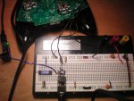
Got the interrupt code to work. Here it is it switches between modes every time you press the button. Pin2 is the sync button and pin1 is the middle pin of the trigger. I have not tested it yet on an Xbox but scope output looks good.
Code:
setint %00000000,%00000100
symbol mode = b0
mode = 0

main:
		if pin1 = 1 then 'trigger is being pressed
select mode
case 0
	dirs = 2
		high 1
	pause 125
		low 1
	pause 125
	DIRS	= 0
case 1
	dirs = 2
		high 1
	dirs = 0
endselect
		endif
	goto main

interrupt:
if pin2=0 then interrupt
	if mode = 0 then
		mode = 1

	else if mode = 1 then
		mode =0
	endif
setint %00000000,%00000100
returnI just treid the matrix Again just for fun And I got a working code and circuit. Again I still have to test it on an Xbox but scope looks good.
The circuit is pin1 connected directly to the middle pin of the trigger and pin2 connected to the middle pin of the sync button.
Here is the code
The circuit is pin1 connected directly to the middle pin of the trigger and pin2 connected to the middle pin of the sync button.
Here is the code
Code:
setint %00000000,%00000100
symbol mode = b0
mode = 0

main:
		if pin1 = 0 then 'trigger is being pressed
select mode
case 0
	dirs = 2
		low 1
	pause 125
		high 1
	pause 125
	DIRS	= 0
case 1
	dirs = 2
		low 1
	dirs = 0
endselect
		endif
	goto main

 interrupt:
if pin2=0 then interrupt
	if mode = 0 then
		mode = 1

	else if mode = 1 then
		mode =0
	endif
setint %00000000,%00000100
returnok good. the sound card scope works but i can tell that there is a big filtering cap on the line because the picaxe which is putting out square waves puts out these sort of spikes. at least i can measure the frequency but thats about it. also it picks up a 60hz signal and i cant even filter it out.
This is the code for the cg controller. All the circuit is is pin1 connected to the middle pin of the trigger. It will only work on an 08m, x2 or m2 series chips because of pin configurations. Here is the code without the mode switching.
P.S. I might have to rethink using the sync button as the mode button It looks imposable to solder.
Code:
symbol mode = b0
mode = 0

main:
		if pin1 = 1 then 'trigger is being pressed
select mode
case 0
	dirs = 2
		high 1
	pause 125
		low 1
	pause 125
	DIRS	= 0
case 1
	dirs = 2
		high 1
	dirs = 0
endselect
		endif
goto mainsorry just read your last post. Here it is with comments")
Code:
symbol mode = b0
mode = 0

main:
		if pin1 = 1 then 'trigger is being pressed
select mode ' if mode equals 0 then go to case 0 but if it equals 1 then go to 'case one if it eaquals 10 then the picaxe with explode cause there is no 'case ten(not realy)
case 0
	dirs = 2 ' Set pin1 to an output
		high 1
	pause 125
		low 1
	pause 125
	DIRS	= 0 ' set it back to an input
case 1
	dirs = 2 ' Set pin1 to an output
		high 1
	dirs = 0 '  set it back to an input
endselect ' endselect statment
		endif
goto main 'loop[size=+5]WOW[/size] I feel really dumb, and I mean that in a big way. I thought they had patched the uber jitter mod(rt.x.yy), but one of my solder joints just broke. I'm relieved but I feel stupid. Now time to kill some noobs with my full auto pump action! And I changed my configuration so I could use the trigger as an input and output. So now instead of pressing that button on the bottom I just press the trigger. Wow just an awesome moment.
My controller now has 5 modes!
Heres my code if you want it.
Thanks for the help although I indirectly stole your code for switching between inputs and outputs, and put it into my controller.
My controller now has 5 modes!
- rapid fire for black ops 525 rpm
- 3rd burst for black ops 525 rpm
- dual pistol rapid fire for black ops with alternating fire about 1050 rpm combined
- rapid fire for MW2 625 rpm
- and le piece de resistance jitter mod pro aka rt-x-y-y for use on shotguns, and 3rd burst guns, around 730 rpm or more with the burst guns
Heres my code if you want it.
Code:
main:
	setfreq m8 ; set the 14ms clock to 8mhz
	let dirsc = %00000110 ; set output 3 to an input

mode_1:
	if portc pin0 = 1 then rapid_fire ; if the black button is pressed then go to rapid_fire
	if pin4 = 1 then switch_1 ; if the red button is pressed then goto switch_1
	goto mode_1 ; go back to mode_1

rapid_fire:
	let dirsc = %00000111 ; set input portc pin0 back to output 3
	high 3 ; right trigger pull
	pause 121
	low 3 ; right trigger release
	pause 121
	let dirsc = %00000110 ; set output 3 to an input
	if portc pin0 = 1 then rapid_fire ; if black button is still being pressed then go back to rapid_fire
	goto mode_1 ; go back to mode_1

switch_1:
	if pin4 = 0 then mode_2 ; if the black button is released then goto mode_2
	goto switch_1

mode_2:
	if portc pin0 = 1 then rapid_fire_burst;if the right trigger is pulled then go to rapid_fire_burst
	if pin4 = 1 then switch_2 ; if the black button is pressed then goto switch_2
	goto mode_2

rapid_fire_burst:
	let dirsc = %00000111 ; set input portc pin0 back to output 3
	high 3 ; right trigger pull
	pause 121
	low 3 ; right trigger release
	pause 121
	high 3 ; right trigger pull
	pause 121
	low 3 ; right trigger release
	pause 121
	high 3 ; right trigger pull
	pause 121
	low 3 ; right trigger release
	pause 121
	let dirsc = %00000110 ; set output 3 to an input
	if portc pin0 = 1 then rapid_fire_burst_wait ; if the right trigger is still pulled then goto rapid_fire_burst_wait
	goto mode_2

rapid_fire_burst_wait:
	if portc pin0 = 0 then goto mode_2 ; if the right trigger is released then go to mode_2
	goto rapid_fire_burst_wait

switch_2:
	if pin4 = 0 then mode_4 ; if the black button is released then go to mode_4
	goto switch_2

mode_4:
	if portc pin0 = 1 then rapid_fire_dual ; if the action button is pressed go to rapid_fire_dual if not then continue
	if pin4 = 1 then switch_4 ; if the mode button is pressed go to switch_4
	goto mode_4 ; repeat mode_4

rapid_fire_dual: ; this mode will rapid fire both triggers at the same time but will alternate which one is being pressed
	let dirsc = %00000110 ; set output 3 to an input
	high 3  low 2; right trigger pull left trigger release
	pause 100
	low 3 high 2; right trigger release left trigger pull
	pause 100
	let dirsc = %00000110 ; set output 3 to an input
	if portc pin0 = 1 then rapid_fire_dual ; if action button is still pressed goto rapid_fire_dual:
	low 2
	goto mode_4 ; go back to mode_4

switch_4:
	if pin4 = 0 then mode_5 ; if the mode button is released then go to mode_5 if not then continue
	goto switch_4 ; repeat switch 1

mode_5:
	if portc pin0 = 1 then rapid_fire_625_rpm ; if the action button is pressed go to rapid_fire_625_rpm if not then continue
	if pin4 = 1 then switch_5 ; if the mode button is pressed go to switch_5
	goto mode_5

rapid_fire_625_rpm: ;  this is an auto quick scope for the intervention in Mw2
	let dirsc = %00000111 ; set input portc pin0 back to output 3
	high 3 ; right trigger pulle
	pause 100
	low 3 ; right trigger release
	pause 99
	let dirsc = %00000110 ; set output 3 to an input
	if portc pin0 = 1 then rapid_fire_625_rpm ; if action button is still pressed goto rapid_fire_625_rpm if not then continue
	goto mode_5 ; go back to mode_5

switch_5:
	if pin4 = 0 then mode_6 ; if the mode button is released then go to mode_6 if not then continue
	goto switch_5 ; repeat switch_5

mode_6:
	if portc pin0 = 1 then jitter_striker ; if the action button is pressed then go to jitter_striker if not then continue
	if pin4 = 1 then switch_6 ; if the mode button is pressed then go to switch_6 if not then continue
	goto mode_6 ; repeat mode_6

jitter_striker:   ; this is my personal favorite it will take most shotguns and 3 round bursts and make them full auto.
	let dirsc = %00000111 ; set input portc pin0 back to output 3
	high 3 ; press right trigger
	high 1 ; press x button
	pause 32
	low 1 ; release x button
	pause 32
	high 4 ; press y button
	pause 32
	low 4 ; release y button
	pause 32
	high 4 ; press y button
	pause 32
	low 3 low 4 ; release y button and right trigger
	pause 11
	let dirsc = %00000110 ; set output 3 to an input
	if portc pin0 = 1 then jitter_striker ; if the action button is still pressed then goto jitter striker if not then continue
	goto mode_6 ; go back to mode_6

switch_6:
	if pin4 = 0 then mode_1 ; if the mode button is released then go to mode_4 if not then continue
goto switch_6 ; repeat switch_6Here is a video of the mouse version in bfbc2. Post if you want mouse circuit details.Rename the file to .wmv.
Attachments
-
185.1 KB Views: 2
Here is the final xbox code with interrupt. Same circuit. I just bought a pc dongle on ebay so I might not test it on xbox live.
Code:
setint %00000000,%00000100
symbol mode = b0
mode = 0

main:
		if pin1 = 1 then 'trigger is being pressed
select mode ' if mode equals 0 then go to case 0 but if it equals 1 then go to case one if it eaquals 10 then the picaxe with explode cause there is no case ten(not reaaly)
case 0
	output 1 ' Set pin1 to an output
		high 1
	pause 125
		low 1
	pause 125
	input 1 ' set it back to an input
case 1
	output 1 ' Set pin1 to an output
		high 1
	input 1 '  set it back to an input
endselect ' endselect statment
		endif
	goto main 'loop


interrupt:
if pin2=0 then interrupt
	if mode = 0 then
		mode = 1

	else if mode = 1 then
		mode =0
	endif
setint %00000000,%00000100
returnYeah. I have not cut the trace on the cg controllers this entire time. I dont think you have to cut the trace on the matrix either. What version of bf do you have. How do you use readadc for the trigger. What is your gt on bf.
Attachments
-
 743.6 KB Views: 9
 -
 299.9 KB Views: 5
When you go to install the picaxe you should put the chip right above the pins for the right trigger. Theres a small slot in the top part of the controller case, which provides a big enough spot to fit the picaxe and the wiring into without removing the motors. Theres two ways to do this. The first way is less invasive, but the second way gives you much more space to use to fit bigger chips(18m2, 20x2) and a hole for the programming jack I've attached some images.
Also I have thought of another way to have a programming jack in the controller without cutting a hole in the controller's case. There is an attachment for the controller called a "chatpad". It connects to the controller using a headphone jack, and two flat plastic pieces with metal contacts on them. If you remove the connector from the "chatpad" you could wire a 9 pin to the jack(the gray piece in the picture below), making a special serial download cable. You would then cut the traces in the controller that would connect to the chatpad, and wire them up to the picaxe. this could also be done with a play and charge kit but it would be more difficult to make the cable.

Also I have thought of another way to have a programming jack in the controller without cutting a hole in the controller's case. There is an attachment for the controller called a "chatpad". It connects to the controller using a headphone jack, and two flat plastic pieces with metal contacts on them. If you remove the connector from the "chatpad" you could wire a 9 pin to the jack(the gray piece in the picture below), making a special serial download cable. You would then cut the traces in the controller that would connect to the chatpad, and wire them up to the picaxe. this could also be done with a play and charge kit but it would be more difficult to make the cable.