Modding XBox Controller

D396

Senior Member
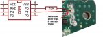
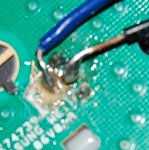
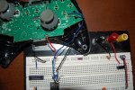
I am currently modding an Xbox controller and I have a question for you. How do you control the triggers I have my picaxe hooked up so It can sense when the trigger is pushed but I don't no where to put the output From the picaxe to make the controller think the button is being pressed when the picaxe output is pulled low. I am using my picaxe to make a rapid fire mod like this one http://www.evilcontrollers.com/products/modded-controllers/evil-specials/auto-burst.html. I got it working on a PC mouse but now I would like to get it to work on a Xbox. Thanks.
 
Last edited:

aduy

Senior Member
Well its not really hi jacking the thread because im making a modded controller. and i would be glad to help.

ok well first what type of controller board are you using, matrix cg cg2 wired or the brand new controller with the chrome guide button?
i have attached a few images to help you determine which one it is.

I would suggestusing a diode in between the the trigger and the chip

later today i will make you a schematic of how i have my other modded controller rigged up( i have a picture of it in post #1 of this thread). and I will post some code if you want.


Attachments

Last edited:

D396

Senior Member
I am modding 3. 2 of which are the new one. the other one is the old one. The one I am doing first is the old one. I didn't' even know there were two types:eek: 
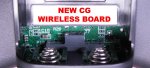
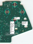
both of them are wireless though
One more thing which direction should the diode go. Cathode to the picaxe or Anode to the picaxe. Thanks
 

aduy

Senior Member
ok so you have one matrix and two cgs i think. well actually i have never done a mod where you just press the trigger and it rapid fires. but i think when you do it like that you can just put a 1k resistor between the picaxe and the middle pin of the trigger. and then hook the middle pin of the trigger directly up to an input of the picaxe. what picaxe are you using by the way im asuming 08m so heres a picture of the how to attach it to the 08m
 

Attachments

D396

Senior Member
Yup I am using an 08m. I will try that this afternoon. I originally cut the trace from the trigger to the main chip and inserted my picaxe there but this might work.
will this code still work
Code:
main:

debug
'if pin4 = 1 then
if pin1 = 0 then
LOW 2
    pause 62
     HIGH 2
      pause 62
  LOW 2
    pause 62
     HIGH 2
      pause 62
     LOW 2
    pause 62
     HIGH 2
      pause 62
     LOW 2
    pause 62
     HIGH 2
      pause 62
     LOW 2
    pause 62
     HIGH 2
      pause 62
     LOW 2
    pause 62
     HIGH 2
      pause 62
     LOW 2
    pause 62
     HIGH 2
      pause 62
     LOW 2
    pause 62
     HIGH 2
      pause 62
endif
'else if pin4 = 0 then
'if pin1 = 0 then
'low 2
'endif
'endif


goto main
 

D396

Senior Member
Now that I think about it I doubt that code will work because the pins are different. Do you have any code that will work for that?
 
Last edited:

D396

Senior Member
Here is a picture of my original circuit. I have not had a chance to test it because I do not own an Xbox but I might test both circuits tonight at a friends
OK never mind I cannot Find a way to upload my pictures they are to big but basically on the matrix type I have a wire soldered to the middle pin of the trigger. And then another wire on the via connected to the button with the trace cut in between. The picaxe when the button is pressed pulses the output pin connected to the via tricking the controller into thinking you are pressing the button really fast. theoretically. It works amazing on a PC mouse so the program itself works. I just have to test it but I was wondering if there was an easier way to do it because I have to do ALOT of them.
Thank you for All your help
 
Last edited:

aduy

Senior Member
ok heres my code for my 14m it has a few different modes, which we can discuss later but you can modify my code to work for your 08m and i configured my chip using diodes, and transistors so that in the program when it says high 3 or which ever pin it will send a signal to the button to tell it that its being pressed. just keep that in mind. you may want to do this to avoid confusing yourself when you are writing the code.

Code:
setfreq m8 ; set internal clock frequency to 8mhz to speed it up

mode_1:
	if pin4 = 1 then rapid_fire_dual ; if the action button is pressed go to rapid_fire_dual if not then continue
	if pin3 = 1 then switch_1 ; if the mode button is pressed go to switch_1
	goto mode_1 ; repeat mode_1

rapid_fire_dual: ; this mode will rapid fire both triggers at the same time but will alternate which one is being pressed
	high 1 ; right trigger pulled
	pause 31
	low 1 ; right trigger released
	pause 49
	high 2 ; left trigger pulled
	pause 31
	low 2 ; left trigger released
	if pin4 = 1 then rapid_fire_dual ; if action button is still pressed goto rapid_fire_dual:
	goto mode_1 ; go back to mode_1

switch_1:
	if pin3 = 0 then mode_2 ; if the mode button is released then go to mode_2 if not then continue
	goto switch_1 ; repeat switch 1

mode_2:
	if pin4 = 1 then quick_scope ; if the action button is pressed go to quick_scope if not then continue
	if pin3 = 1 then switch_2 ; if the mode button is pressed go to switch_2
	goto mode_2

quick_scope: ;  this is an auto quick scope for the intervention in Mw2
	high 2 ; pull left trigger
	pause 570 ; wait for perfect moment
	high 1 ; pull right trigger
	pause 100
	low 1 ; release right trigger
	low 2 ; release left trigger
	pause 1400 ; wait for reload
	if pin4 = 1 then quick_scope ; if action button is still pressed goto quick_scope if not then continue
	goto mode_2 ; go back to mode_2

switch_2:
	if pin3 = 0 then mode_3 ; if the mode button is released then go to mode_3 if not then continue
	goto switch_2 ; repeat switch_2

mode_3:
	if pin4 = 1 then jitter_striker ; if the action button is pressed then go to jitter_striker if not then continue
	if pin3 = 1 then switch_3 ; if the mode button is pressed then go to switch_3 if not then continue
	goto mode_3 ; repeat mode_3
	
jitter_striker:   ; this is my personal favorite it will take most shotguns and 3 round bursts and make them full auto. 
		    ; in black ops this was patched
	high 1 ; press left trigger
	high 3 ; press x button
	pause 32
	low 3 ; release x button
	pause 32
	high 4 ; press y button
	pause 32
	low 4 ; release y button
	pause 32	
	high 4 ; press y button
	pause 32
	low 1 low 4 ; release y button and right trigger
	pause 11
	if pin4 = 1 then jitter_striker ; if the action button is still pressed then goto jitter striker if not then continue
	goto mode_3 ; go back to mode_3

switch_3:
	if pin3 = 0 then mode_1 ; if the mode button is released then go to mode_1 if not then continue
	goto switch_3 ; repeat switch_3
 

aduy

Senior Member
ok well i need to see your circuit so just go into paint and make the image smaller and then save it and upload it.
 

D396

Senior Member
Thanks for the code I will try and modify it. I only need the right trigger for jitter fire. Also could you post a schematic on how you wired it. Have you tested it and does it work? And what do you mean by patched in Black Ops?
 

aduy

Senior Member
yes it works. um i will post a schem later today of my controller mod. and what i mean is it the jitter mod used to work and now it doesn't. you can still do the basic rt-y-y jitter but that doesn't work on the shotguns. when they come out with updates to the game its called a patch. in this case the patch was to block some modded controllers. there may be ways to get around this patch but i haven't had the time to find them. oh and to post an attachment you do whats posted in my attachment.
 

Attachments

aduy

Senior Member
ok i think you need a resistor between the ouput of the picaxe and the rt trace on the controller. your wires are a little thick. try to find some stranded 30 or 28 gauge. also use some alcohol to clean off the flux.
 

D396

Senior Member
I just tried your circuit with the resistor and with my multimeter it worked perfectly. My multimeter reads 8 Hz at the center pin of the trigger. Thanks.
I will post tomorrow on how it works on the Xbox. Attached is my schematic. I hope it inst copyrighted;)
 

Attachments

aduy

Senior Member
0.8 volts i think you mean and its good that it worked cause i was guessing based on mods that i have done. cg controllers are easier to mod on then matrix. the matrix requires some extra transistors and such. have you looked at the xbox-scene forums? they would probably know more about what you are doing after all im only 17 and this is only a hobby of mine.
 

D396

Senior Member
No I meant 8 Hz I have the picaxe set to pulse it at 8 Hz when I press the trigger. the one I an currently using is a matrix one so I don't know how it works if I don't have any extra components. No I haven't check the Xbox forums.
P.S. I am younger than you
 

aduy

Senior Member
ok well i dont know too much about that whole matrix thing but if it works then it works and its nice to know im not the only high school kid who can actually do electronics. and btw i finally got the anti sway mod to work i just need to find the pattern and ill e golden.
 

aduy

Senior Member
one problem that i have had using wireless controllers is that not only do they suck batteries, but when they run low on power the timings will get messed up and even stop working.
 

D396

Senior Member
Well It didn't work last night. I pressed the trigger and it fired once not full auto. I am going to take another look at it today.
 

D396

Senior Member
OK here is what I got using my oscilloscope. When the trigger is pressed the wire which is connected to the input and the output is pulled high the picaxe pulses it put instead of going to ground and then to 3 volts it goes from 1.5 to 3 and back. I have attached my circuit, code , and oscilloscope readings. There may be a simple circuit to fix my problems but I cannot find it. Thanks
 

Attachments

aduy

Senior Member
which game are you doing this for cause if its black ops its really hard to get the fal and m14 to rapidfire
 

aduy

Senior Member
also your timing seems really slow just from my experience running at 4 mhz you should have your pauses set at about 30-18 time units.
 

aduy

Senior Member
oh i thought of something to bypass the mod block. on the three pins for the right trigger find out what the voltage of the pin closest to the back. that should be the maximum output of your picaxe. also you can attach a capacitor to smooth the square signal to make it more human like. oh what is the debug for, because that may be whats slowing the program down.
 
Last edited:

aduy

Senior Member
oh i did a little work on your code try this

Code:
setfreq m4

main:
if pin1 = 0 then goto main
goto burst

burst:
high 2
	pause 166
low 2
	pause 166
high 2
	pause 166
low 2
	pause 166
high 2
	pause 166
low 2
	pause 166
if pin1 = 1 then goto waiting
goto main

waiting:
if pin1 = 0 then goto main
goto waiting
 

D396

Senior Member
That doesn't work. I am almost positive it is the circuit. When I press the button it is pulled high. The picaxe reads the high and tries to pull it back low but It cant get all the way to 0v. So when I pull the trigger instead of pulsing 3V 0v 3V 0v and so on It pulses 3v 2v 3v 2v And the controller does not read that as low so it ignores the pulses.So basically I need a circuit so that the picaxe will overpower the pullup on the trigger making it low
 

aduy

Senior Member
ok what you need to do is actually cut the trigger's trace and use the trigger as the input for the picaxe and the output from the picaxe should be attached some where on the trace that you cut. if you want you could install a switch to reconnect the trace and the trigger, or you could do it in the program by having it so that when the trigger is pushed the picaxe sends a signal to the controller. oh and that code i put up is more of what you want i think. when pin1 goes high it will fire three rounds and then wait until you release the trigger to fire another three rounds. the upside to this over what you did is that the only pause between bursts is how long it takes you to pull the trigger again.
 

D396

Senior Member
where should I cut the trace and were would the output of the picaxe go. Do you have any pictures.
P.S. this is how I did on my mouse and was originally going to do it on the controller but I did not know were to attach the picaxe.
 

D396

Senior Member
OK so I did that to my matrix and I wont fire at all even with the inputs and outputs connected. Did I do something to the via. I removed the top layer of solder mask.
 

aduy

Senior Member
check to make sure that a signal can be sent by using a wire to connect the bottom pin of the trigger and the hole where i told you to solder. if the controller did not register a pull of the trigger, you need to re-solder that hole until it does.
 

aduy

Senior Member
can you post a picture of how you did it. also if you save your picture as a .jpg you can do a higher resolution which would be much better than the teeny tiny pictures.
 

aduy

Senior Member
you may be shorting the via with ground. i think you took off too much of the stuff covering the traces. so does it send a signal or no?
 

D396

Senior Member
what do you mean by send a signal. The picaxe sends the signal but the game does not respond.
 
Top