Borehole well water level sensing

Jeremy Harris

Senior Member
On another thread I took things off topic by looking at ways to measure water level in a borehole well. This thread is to hold those posts moved by admin (I hope) so please don't add posts here until the old posts have been moved over.

The challenge I have is wanting to measure the depth of water in a 53m deep water supply borehole. The resting water level is usually around 4m from the surface, but when the well is pumped very hard for long periods it can drop to around 11m below the surface. The pump sits at about 25m below the surface.

I would like to periodically measure the water level, just for reassurance that all is well, and to track any seasonal changes. At the moment I have to measure the water level by dropping a pair of wires down the hole, with a water conductivity switch on the end, that operates a beeper when it touches the surface of the water. I have markers on the wire that show me the depth.

--------------------------

From other thread ...

It's a pity those "time of flight" sensors don't have a longer distance measurement range. I've been wanting to put a simple water depth indicator on our borehole well for some time now. I know that the water level sits around 4m down when the well isn't being pumped, and that after prolonged pumping at the maximum pump rate (around 2000 litres per hour) the level drops to about 11m down, but it would be nice to have a simple monitor that shows the water level. The pump is around 25m down, so well below what I think is the worst case low level, and the well is 53m deep.

I like the idea of having a small, sealed, unit that just shines a laser down to the water surface and picks up the reflection. Easier to make watertight than an ultrasonic ranging system, and because the well is totally dark, the performance of any sensor should be improved.

Many years ago, I built a distance measuring system for doing cave surveys. That used a low frequency (a few hundred Hz, IIRC) sine wave modulated point source LED (one intended as a fibre optic driver) and collimated it to a near-parallel beam, with a single lens. I used a bigger lens (around 30mm in diameter) for the receiver, to focus the reflected light back to a photodiode. A sideways pinhole allowed some modulated light from the transmitter to also hit a reference photodiode. The signals were amplified by a pair of identical tuned amplifiers, rather like very low frequency radio IF amplifiers, then fed to a pair of identical threshold comparators. The difference in phase between the transmitted light and the received light gave the range, with pulses that could easily be measured by a small microprocessor.

I could build the same sort of system again, as I still have all the parts from the original survey unit, but it would be a bit large to fit under the well head cap (the well is roughly 120mm in diameter). I wonder if any of the modules mentioned here could be modified to do the job? My biggest problem last time was the optics, and I had an aluminium block machined up with two parallel holes, with small apertures for the LED/photodiodes and a rebate to take the lenses. I may just get one of those sensors with the optics and see if there's a way to modulate the thing at a few hundred Hz and do as I did before with the receiver.
 
Last edited by a moderator:

Jeremy Harris

Senior Member
I did look at them, but sadly that's out of my price range!

I suspect it uses the same modulation technique that I used all those years ago, though. I first read of it in a Texas Instruments Application Note back in the early 1980's, and was fascinated by the use of low frequency light modulation to convert the time of flight of light down to an easily measurable phase difference between the transmitted and reflected signals.
 

techElder

Well-known member
I would think ultrasonic sensors can be provided with IP67 sealing, but you're only going to get about 10 meters out in open air. Your problem is that 120mm bore diameter. You'll get many extraneous reflections from the bore walls IMHO. Plus your bore isn't "clean" in the sense that you have wires and pipes going down into it.

You'd be better off with a mechanical gauge inside of another pipe run down the bore; basically a float gauge in a protected tube.
 

Jeremy Harris

Senior Member
I would think ultrasonic sensors can be provided with IP67 sealing, but you're only going to get about 10 meters out in open air. Your problem is that 120mm bore diameter. You'll get many extraneous reflections from the bore walls IMHO. Plus your bore isn't "clean" in the sense that you have wires and pipes going down into it.

You'd be better off with a mechanical gauge inside of another pipe run down the bore; basically a float gauge in a protected tube.
Similar to my thoughts about using an ultrasonic system - the echoes would be a major problem.

I have got a nice quality Microgage stainless 100psig pressure transducer, scrounged years ago from an aerospace project. I had been toying with the idea of sticking it in a watertight enclosure, putting one of those HX711 bridge amplifiers in there, together with an 08M2 and running serial data and power up through a small pipe to the surface (the pipe would give the surface gauge pressure reference needed, too). The problem it that it's another thing to get tangled up around the pump pipe, cable, safety rope, etc, every time the pump twists a bit as it starts and stops, hence the desire to try and do it from the surface. It's enough fun pulling the pump up now (I fitted it myself and have had it in and out twice when I was setting things up). Another thing to get tangled up would just make things worse, I think.

Maybe the price of those neat long-range optical range sensors will come down over time.
 

Jeremy Harris

Senior Member
Hi Jeremy,

Here's another of my half baked ideas.

Your bore hole is like an organ tube, and will have a resonant frequency depending on its depth.

By measuring the amplitude of a swept frequency audio signal you could determine the water level.

Cheers,

Buzby

EDIT : Here are the tools for calculating stuff : http://hyperphysics.phy-astr.gsu.edu/hbase/Waves/opecol.html
That is a damned good idea!

The thing does "boom" very loudly, the noise from it is clearly a single tone when you tap or knock the plastic liner. A waterproof speaker and mic, set into the lid and set to track the resonant frequency, would probably do the job. I bet the pipe is a damned good band pass filter, with a pretty high Q, so a tiny bit of excitation from a speaker should get it resonating. If the speaker and mic were in a phase locked loop, then it might well be possible to get a frequency output that's proportional to water depth. The only thing I'd have to watch is whether or not the pump motor messed things up, as it is bound to have 50Hz harmonics that might interfere with the higher order resonances.

From a quick look it seem that if I can filter things to only receive the fundamental of the closed pipe, then I'd be looking for a frequency range of around 7Hz to 21Hz, which looks as if I should be able to filter out anything over about 25Hz pretty vigorously, so the thing stays locked on to the fundamental.

I wonder if anyone has tried to make a Picaxe work as a low frequency phase locked loop? It seems possible to have a mic, amplifier, LPF and comparator feeding in to a pulsin measurement, and then driving a frequency output to the excitation source, looking for resonance, where resonance would look like a 50% duty cycle at the resonant frequency (I think). Filter phase shifts may be a problem, but I shall have to give this a bit more thought!
 

Jeremy Harris

Senior Member
Thinking about it some more, I don't think I need anything so complex as in the ramblings above. I only need to make spot measurements at intervals, so something like a mic, filter, amplifier and rectifier, fed to an analogue input, with a slowly swept frequency output going to a small, low frequency capable, speaker, would do the job. The high Q of the closed pipe at resonance may well be enough to allow the peak to be detected via the ADC and then the excitation frequency output used to give the water depth. I need to hunt around for a low frequency excitation source. I doubt a small speaker will do much below about 100Hz, let alone 7Hz that I really need to get the sort of worst-case depth I'm likely to see.
 

Buzby

Senior Member
Hi Jeremy,

I'm glad you like my idea, and think it's worth a punt.

Does the liner protrude above ground level ?.

If so, you could strap the exciter to it.

For low frequency stuff like this you could even contemplate making your own exciter.

Maybe a variable speed saw tooth wheel running against a tab fixed to the liner.

Or an eccentric weighted motor, like a giant phone vibrator ?

Cheers,

Buzby
 

Jeremy Harris

Senior Member
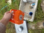
Yes, the liner sits around 150mm above the bottom of a concrete pit, with a flange on top that's bolted down. Here's a photo taken before I fitted the pump or flanged top plate that supports the weight of the pump, pipe, safety rope, cable etc (I'm using a home-made beeper detector to measure the resting water level in this photo):

View attachment 20524

I like the idea of something that just vibrates the pipe. It may well be that I could just fit something like an offset weight to a motor shaft and use that to vibrate it enough to detect the resonance. The resonance seems to be very pronounced and easily excited, as the thing really does make quite loud booming noises when you're lowering or raising stuff and hit the side of the pipe.
 

Attachments

Buzby

Senior Member
Message for Admin.

Can you split this from around post #49 into a new thread ?

It's gone a bit off topic, but seems like it might have wings.

Cheers,

Buzby
 

Jeremy Harris

Senior Member
On another thread I took things off topic by looking at ways to measure water level in a borehole well. This thread is to hold those posts moved by admin (I hope) so please don't add posts here until the old posts have been moved over.

The challenge I have is wanting to measure the depth of water in a 53m deep water supply borehole. The resting water level is usually around 4m from the surface, but when the well is pumped very hard for long periods it can drop to around 11m below the surface. The pump sits at about 25m below the surface.

I would like to periodically measure the water level, just for reassurance that all is well, and to track any seasonal changes. At the moment I have to measure the water level by dropping a pair of wires down the hole, with a water conductivity switch on the end, that operates a beeper when it touches the surface of the water. I have markers on the wire that show me the depth.
 

hippy

Technical Support
Staff member
I have copied the posts from the other thread. The forum keeps the same timestamps so I edited the first post to to include the above post to give it better context.
 

Buzby

Senior Member
The pipe is narrower than I imagined.

Put some ferrous tape round it, then an electromagnet coil. ( You'll probably have to wind that yourself. )

Drive that with a power amp of some kind.

This should excite the pipe, and no moving parts should be more reliable.
 

Jeremy Harris

Senior Member
The pipe is narrower than I imagined.

Put some ferrous tape round it, then an electromagnet coil. ( You'll probably have to wind that yourself. )

Drive that with a power amp of some kind.

This should excite the pipe, and no moving parts should be more reliable.
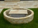
The pipe is actually 125mm OD, and 119mm ID, I think, so 3mm wall thickness, and made from PVC. For interest, it comes in 3m long sections, with Acme threads on the ends (internal one end, external the other) and the lowest 4 sections have a slotted filter, in that the pipe has vertical slits, 0.5mm wide and around 20mm high, all around it. On the outside of the slotted pipe sections there is a bed of ground glass, that acts as a filter. The actual drilled borehole is 200mm in diameter, so there is around 37.5mm of filter material all around the lower slotted section. The glass media extends up for a few metres above the slotted section and is then covered with Bentonite, clay that forms a watertight, and bug-tight, seal around the liner, right up to the surface. At the surface the liner is encased in concrete at the base of a standard drain-type concrete manhole. Since that photo was taken the system has been completed and the house completed, and the well now has a wall around it and a stone cover, and will eventually be a feature in the garden. This is what it looks like now:

Borehole well head.JPG

It would be easy to just bolt something to the flange at the top in order to produce a sound. The top plate is made from 12mm thick PVC sheet and bolted down with 6 off stainless screws to the flange that is bonded to the top of the 125mm pipe, so is around 150mm in diameter. It has a 1" BSP fitting in the centre for the pipe that comes up from the pump, a couple of cable entry glands, one used for the pump power cable and the other fitted as a spare (currently blanked with a cap). There's also a hand screw fit 1 1/2" PVC capped pipe in the top plate, that I can unscrew and use to drop the water level measurement wire down. Finally, there's a stainless eye bolt under the top plate, to which the pump safety rope is tied. The pump pipe is a 25m length of 25mm OD MDPE water pipe, and that jerks and flexes with the torque reaction from the pump starting and stopping (it's a 1hp, 3" diameter pump, so has a fair bit of power).

I will have a play around and see what can be done with just a vibrating motor, I think. I have some small stepper motors around, with drive boards, and IIRC they can run at around the right sort of rpm. I might be pushing it to get 1300 rpm, but they might do it. If they can, then setting the frequency of the vibration actuator would be easy, just send pulses out at the right rate. This would make the system you described, Buzby, of sweeping the frequency and looking for the resonance peak pretty easy to implement with a Picaxe, with just a microphone, some filtering and amplification and rectifying to a voltage fed into an ADC.
 

hippy

Technical Support
Staff member
At the moment I have to measure the water level by dropping a pair of wires down the hole, with a water conductivity switch on the end, that operates a beeper when it touches the surface of the water. I have markers on the wire that show me the depth.
You could perhaps automate that. Have your conductivity sensor spooled-up and lower it down with a DC motor or stepper. How long it takes before conducting will be proportional to the depth.
 

Jeremy Harris

Senior Member
You could perhaps automate that. Have your conductivity sensor spooled-up and lower it down with a DC motor or stepper. How long it takes before conducting will be proportional to the depth.
That's another good thought. I have some small geared motors around somewhere, and if I used thinner wire I could get the spool size down a fair bit. There's now a fair bit of space above the borehole top plate, as I added a second concrete manhole ring since the first photo, so I might be able to make something that fits onto the threaded bit of 1 1/2" pipe, with a guide to lower the wire down the centre.

The spool needs to hold around 12m of twin core wire, so the bigger the diameter the better, I think.
 

Buzby

Senior Member
If you had fixed long bare wire, using earth as return, would the current ( albeit small ) be proportional to the length underwater ?
 

hippy

Technical Support
Staff member
Rather than use bare contacts which might not fare well when left exposed in air, I was thinking a small base plate with a float switch attached underneath it. As the plate approaches the water the switch will be forced underneath the water, raising the float and opening/closing the switch -

Code:
  ___                      ___
 ( O )                    ( O )
  | |                      | |
.------------------------------.
|                              |
`------------------------------'
                |       |
         _______|___    |
        |           \   |
        |          O )  |
        |___________/---'
.
 

Jeremy Harris

Senior Member
If you had fixed long bare wire, using earth as return, would the current ( albeit small ) be proportional to the length underwater ?
Almost certainly, but I think there are a couple of problems with this idea. The first is that the conductivity of the earth varies a fair bit, and may well swamp the effect of a change in water level. The second is that the conductivity of an immersed bare wire will change with time, as it corrodes or attracts surface deposits (the water is fairly hard).

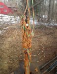
If I can get a solution to work that doesn't need anything to go down the borehole at all, then that would be my favourite. There's always the risk of getting tangled in the pipe/cable/safety rope that run down to the pump, something that does seem to happen when people drop probes and things down boreholes. I had a lot of problems getting good water from our borehole, as there's a lack of expertise here in the UK. I ended up going on to a US forum, where there were hundreds of members with borehole water supplies. The forum itself was a bit commercial, but one guy from Texas emailed me lots of times and gave me a fantastic amount of help off-line. With this help I was able to clean the borehole out (there were issues with the way it was drilled and commissioned initially) and design and build a treatment system that gives us really nice water, with no chlorine etc. As an idea of the sort of tangle you can get down these things, thins is a photo from a US forum where a pipe broke and the pump wound up the cable:

Pump and wire tangle.jpg
 

techElder

Well-known member
Not to get too far out but add a safety wire or you might end up with what in the Texas oil business is called a fishing job.
 

Jeremy Harris

Senior Member
Rather than use bare contacts which might not fare well when left exposed in air, I was thinking a small base plate with a float switch attached underneath it. As the plate approaches the water the switch will be forced underneath the water, raising the float and opening/closing the switch -

Code:
  ___                      ___
 ( O )                    ( O )
  | |                      | |
.------------------------------.
|                              |
`------------------------------'
                |       |
         _______|___    |
        |           \   |
        |          O )  |
        |___________/---'
.
That would work OK, but there's still the potential for tangling. The pump kicks when it starts and stops, twisting the long pipe. It causes no harm, but is an inevitable consequence of a rotor spinning up quickly or slowing quickly, with a lot of power.

The switch I use on the hand-held dipper has gold contacts, and is designed for things like basement flood alarms, where it's either wet, or in a high humidity area, all the time. I don't think corrosion would be a problem, and I did get half a dozen of these switches that I still have, with the idea of hanging a "daisy chain" of them down the well to give a very rough indication of water level. It was the potential for getting tangled up that stopped me doing this!

I think I need to at least try the acoustic system out, even if it's just with a jury rigged noise maker, a mic and the 'scope, to see whether the resonant frequency is readily detectable. It may well be that just having something like a solenoid that bangs an anvil on the top plate would give enough to excite the pipe at the resonant frequency, in which case it's just a matter of firing the solenoid "hammer", having a mic with some amplification, filtering and a comparator, and using multiple pulsin instructions to read the pulse width a few times and get an average.
 

Pongo

Senior Member
I have a similar well except the water can be 80 meters down. The bubbler method of measuring water depth is pretty reliable. A open ended tube is fed down the well until the end is under water and a small compressor used to pressurize it. The pressure will increase until it flat lines when it overcomes the water pressure and bubbles out the end of the tube. The calculation is detailed here.

Use 1/4 or 3/8 nylon tube (weighted at the lower end), an inexpensive air brush compressor (must be oil free), pressure sensor (Motorola now Freescale?), picaxe and a few other bits :)

(I haven't tried the numbers to see if it works for a shallow well.)
 

Jeremy Harris

Senior Member
Not to get too far out but add a safety wire or you might end up with what in the Texas oil business is called a fishing job.
I have one, fixed to a stainless eye bolt under the top plate.

I made a submersible camera when I was having all the problems with the well initially, and even shot a video of it going down the borehole (it's here, on YouTube: https://www.youtube.com/watch?v=xmxXTku9_90 - note that I settled the case with them without legal action!). You can see the four slotted sections of the liner right at the end of the video. The orange stuff is ferric oxide, from when the borehole was shock sterilised with bleach. This oxidises the ferrous oxide in the water ("clear iron") into ferric oxide ("rust") that precipitates out on any horizontal surface or edge.

After doing this, they asked me to make them a submersible camera, a very small one (1 1/4" diameter, including the lights) as they had to go "fishing" down another borehole to retrieve a drill bit.................
 

Buzby

Senior Member
Hi Jeremy,

It is looking like the resonance idea is most promising at the moment, and very easy to test.

There are plenty phone apps to generate sinewaves, ( some with sweep abilities as well ), a simple amp/speaker, and a laptop scope should let you test the idea before building anything.

Cheers,

Buzby
 

AllyCat

Senior Member
Hi,

+1 for the "Organ Pipe" method (Buzby beat me to it). I suspect that a Continuous Wave (i.e. resonance) method might be the most accurate, where the depth is wavelength / 4. Perhaps a "subwoofer" will go to a low enough frequency, or you might work with harmonics, e.g. it should be possible to identify if two adjacent resonant frequencies are e.g. 7th : 9th or 9th : 11th, etc..

I believe that electret microphones have quite a good low frequency response, but for even lower frequencies you might consider repeated measurements from a PICaxe-friendly I2C barometric pressure sensor, which can be low cost and have remarkable sensitivity.

Cheers, Alan.
 

Jeremy Harris

Senior Member
I have a similar well except the water can be 80 meters down. The bubbler method of measuring water depth is pretty reliable. A open ended tube is fed down the well until the end is under water and a small compressor used to pressurize it. The pressure will increase until it flat lines when it overcomes the water pressure and bubbles out the end of the tube. The calculation is detailed here.

Use 1/4 or 3/8 nylon tube (weighted at the lower end), an inexpensive air brush compressor (must be oil free), pressure sensor (Motorola now Freescale?), picaxe and a few other bits :)

(I haven't tried the numbers to see if it works for a shallow well.)
As mentioned earlier, I have a nice quality 100psig pressure sensor (an aerospace standard one, from Microgage) that I could fit into a watertight housing, together with an HX711 bridge amp and a Picaxe 08M2. If I fitted this housing and electronics to a long length of thin pipe, with four wires coming up through it, I could get a direct level reference from the gauge pressure. I could make the same thing work with a bubbler air system easily enough. Coincidentally, there's a homebuilt aircraft fuel gauge that works the same way, but uses a small hand air pump to pump air down the tube, so you can make bubbler depth measurement systems work well even at really shallow depths.

If I can avoid having something else hanging down the well then I reckon that's a big advantage for me, though. I've hauled the pump in and out of my well three times, the first two times was the "old" Grundfos pump, that got sand damage, and that was about 45m down, the last time was the new pump that I only dropped 25m down (it's a LOT easier pulling a pump only 25m!). I now have a tripod rig that I can put over the well to make pulling the pump out easier, but it's never a fun job.
 

erco

Senior Member
How about a long multiwire insulated cable running down the well, maybe old 300 twin lead for TVs. Wouldn't the capacitance change measurably as the water level changed? Calibrate that.
 

Jeremy Harris

Senior Member
Somewhere I have some electret mics, and they do seem to work down to low frequencies OK, as they seem very good at picking up wind noise. I suspect it won't take much to get the pipe to resonate, as it's closed at both ends. There is a small sintered bronze filter on the top plate, to allow the air pressure to equalise and keep bugs out, but I'm really looking at a pipe, closed at both ends that can vary in length from around 4m to about 11m.

Given the low frequency needed, I've been wondering if a piston driven by a coil might do the job as a speaker, or perhaps a rubber diaphragm driven by a cam from a motor (perhaps a geared up stepper motor). I need to do some tests to see how a closed pipe behaves, because I've only experienced it "booming" at its resonant frequency when the top has been open.
 

geezer88

Senior Member
The bubbler method of measuring water depth is pretty reliable.
I've used this method for years in my well. It is easy, and repeatable. A few thoughts might be helpful. You want the air flow rate to be low enough that the pressure drop across the air tube is insignificant compared to the "signal" pressure, however, if the air flow rate is constant, you can null out the difference. The tube can be remoted quite a distance if it is more convenient, but again the pressure drop will be greater, and more time required for the system to come to equilibrium after turning on the air pump.

You will want to get a transducer that has a full scale range a little larger than the anticipated range of depth, including some leeway for that unusual "dry year". There are lots of cheap sensors out there that will work, but try to get one that conditions the signal and is temperature compensated to reduces the hardware design.

If you remote the sensor and air compressor, and the air line travels through a space that freezes, you may have trouble with condensation freezing in the tube and plugging it.

All this has assumed that you want an "electronic signal". If you just want to go out now and then with a bike pump and a mechanical gauge, you simply hook up your "tester" to the tube installed in the well, pump until the pressure is constant, take your reading and you're done. I reworked the dial of a cheap pressure gauge to read feet of water, and walked the 900 feet to my well now and then for a reading.

tom
 

Jeremy Harris

Senior Member
Thanks for all the advice - it's noticeable that the practical knowledge all comes from friends here from the US!

This mirrors my experience in trying to get good advice here in the UK - it seems so few people live "off grid" in terms of not having a mains water supply here that there really are very few people around with the depth of knowledge to deal with borehole well problems, particularly when it comes to domestic drinking water. There are plenty of drillers sinking wells for farms, where the water quality isn't generally that important, but I found that drillers seems to just know about drilling the hole and lining it, and you're then pretty much on your own when it comes to sorting out all the other stuff needed to get a good, reliable, supply of drinking water.

In our case, it was a new house build, and the original idea was to have the well working ready for mixing concrete, making tea etc before the house went up. As it turned out, we had a years worth of well problems, and I was shipping water over to the site in 5 gallon containers every day, often several trips a day, all through the build. It delayed our build for around a year, all told, first sorting out why we seemed to have nearly 20m of hard packed sand at the bottom of the well (we didn't, the well was drilled and lined 7m short), then having major problems with lots and lots of fine sand being pumped up. We knew we were taking water from a "running sand" aquifer, and the hydrologist had designed and specced the well to account for this, with a target depth of 55m and lots of glass filter media packed around the slotted liner section. Because our drillers "missed" finding water (despite the fact that we can pump at 2000 litres per hour, continuously, for days on end; I pumped it non-stop for two weeks to try and clear the sand, on the advice of the drillers, which didn't fix the sand problem but did wear the new Grundfos pump a lot) they carried on (supposedly) drilling to 70m, but in reality we found they'd only drilled to 53m. The aquifer is where the hydrologist said it would be, around 45m down, so as it turns out the well is at around the right depth and to the right sort of spec. The problem was that we our pump was way too deep, and we were pumping the well too hard to try and clear it, which was just pulling more fine sand through.

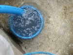
I ended up following the advice of a really helpful chap in Texas, who pretty much talked me through how to make an air lift and clean out the well. That advice alone was invaluable, as I air lifted the hole, which resulted in sand like this coming up from the bottom (this is the air lift in operation):

Sandy water coming out 1.JPG

After clearing the sand, the Texan chap suggested I give the well a "blow job", pumping air from a pipe at the bottom, using my small compressor, and letting the whole liner act as the lift pipe. I was amazed how effective this was, and how much water my small compressor would lift from the well. It really cleaned things out:

Blow job 1.JPG

After all this work, the well only seemed to be 53m deep, as the air pipe was hitting something solid at that depth (as far as I could tell). The drillers were telling me this was just packed sand, but by now I had no faith in anything they told me, so I made up a camera to take a look.
 
Last edited:

Jeremy Harris

Senior Member
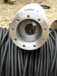
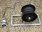
The camera rig looked like this:

DIY borehole camera - smaller lighting ring.JPG

DIY borehole camera rig 1.JPG

And was made from an old underwater UAV camera housing I'd scrounged from a scrap pile years ago (which had no camera in it). I fitted an old car reversing camera I had, made up an LED lighting ring (had two goes at this, as the first was just a bit too close to the well bore, so was very slow to sink) and used this to video the well. I found the PVC end cap on the liner at 53m down, which proved beyond doubt that I didn't have a 70m well! As the drillers charge by the metre for both drilling and lining, we had a "discussion" about their bill and compensation for all my lost time, and settled out of court.

To be fair, the drillers had a load of problems, with rigs breaking down, waiting for spares, switching rigs half way through the job, etc, so I can see how their drill logs got messed up (one rig used 2m long rods, the other used 3m long rods, so the numbers got mixed up somewhere along the line, and when they though they were at target depth they were really a long way short, hence the extra drilling (or so they thought) to 70m.

Once cleaned out, shock chlorinated to disinfect it and with the new pump fitted at 25m down, rather than 45m, the well has been fine, as long as I don't pump it too hard. I have a Dole valve to limit the pump rate, and two 300 litre pressure tanks, plus one 100 litre pressure tank, so in practice we have loads of water and can run the showers till the hot water runs out, without the pressure dropping below the pump cut-in pressure.

I had to treat the water to get the iron out, and to remove a little bit of hydrogen sulphide, but again had great advice from my friend in the US, so we now have really good water.
 

Pongo

Senior Member
Wow, that's quite saga! I've had good experience except when a new replacement pump failed after 2 hours and they had to pull all 80 meters twice in the same day. Yes, 10% or more of US households have a well, it's probably closer to 50% where I live.

Since we've already strayed more than an little, may I ask what you are using for iron filtering? I have BIRM followed by a potassium salt softener to tame mine.

Nice job on the camera :)
 

inglewoodpete

Senior Member
I don't know if anyone has discussed the method used locally for water level depletion due to pumping faster than the bore can be replenished.

My bore casing is PVC with a stainless steel screen at the bottom (fully sealed apart from the screen perforations). From memory, the bore is 30 metres deep. The pump 'spear' reaches practically to the bottom, obviously. The difference is that the top of the bore casing is sealed, with the water outlet coming through the cap. As water is pumped, it creates a vacuum in the upper part of the casing, forcing surrounding water through the screen into the casing at the bottom.

I have never wondered how deep the water is. This system has not let me down in 18 years.
 

Pongo

Senior Member
I don't know if anyone has discussed the method used locally for water level depletion due to pumping faster than the bore can be replenished.

My bore casing is PVC with a stainless steel screen at the bottom (fully sealed apart from the screen perforations). From memory, the bore is 30 metres deep. The pump 'spear' reaches practically to the bottom, obviously. The difference is that the top of the bore casing is sealed, with the water outlet coming through the cap. As water is pumped, it creates a vacuum in the upper part of the casing, forcing surrounding water through the screen into the casing at the bottom.

I have never wondered how deep the water is. This system has not let me down in 18 years.
That's an interesting concept. What diameter is the bore and how far down is the water level?
 

inglewoodpete

Senior Member
That's an interesting concept. What diameter is the bore and how far down is the water level?
Water is about 12 metres below ground level according to the government's on-line water atlas. The (permanent) outer casing is about 125mm. I think it's that size to fit into the temporary 150mm/6" casing that is used while drilling the hole. The assembled 125mm gear is lowered into the outer casing before the outer case is recovered. The ground is quite sandy.
 
Top