Borehole well water level sensing

Willie...

New Member
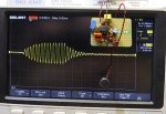
Hey, Alan! Thanks for the input! The 32ms of the burst is measured on the O'scope, so it is accurate at 16MHz. :)

I'll have to try your code, and see how it works. I would imagine that the 08M2 chip should still be more than powerful enough to process this... unless it lacks a timer, but I don't think that's the case. I don't need microsecond accuracy, after all. :) I'm only dealing with a maximum range of about 150ms echo to 390ms echo, and want to convert that into a percentage of water level. Sadly, right now, I just found out that I'm close to zero! :(

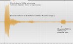
Minutes before posting this reply, I did a REAL WORLD TEST with a very crude speaker setup and my phone to record it. The ping and the echo are truly distinct.

NOTE: The 630 Hz echo is the SAME, regardless of the water level! I have several recordings of various water levels, and confirmed that with the FFT analysis of my audio editor. :)

Here's what's really cool! When I send 20 cycles of 630 Hz down... I get twenty cycles back! :eek: There is minimal "ringing", so... well, a picture is worth 1,000 words. The sounds are as crisp and clear as this audio editor's image implies! I hear the "PIP!" of the speaker, and the "pip" of the echo. It should be very easy to make a clean logic pulse from this echo, to stop the timer in the PICAXE.
 

Attachments

Willie...

New Member
Follow-up for Alan - I tried your code, and I had to tweak a few things to get it right on my chip. "Cycles" needs to be 206, and the pause of 62ms had to be 64, *BUT* when run and watched on the o'scope, the number of cycles varied from 19 to 20, sometimes a "half" cycle also appeared. Granted, that's not critical, I just found it interesting and worthy of mention. :) With the FOR/NEXT loop, it was always 20 (for obvious reasons).

Suffice to say, I'm quite happy with this 630Hz tone burst, and may reduce it to just 10 cycles later, as the project progresses. I need to see how well the signal filtering circuits work, to determine if any changes to the number of cycles are going to be needed.
 

AllyCat

Senior Member
Hi,

The "jangle" at around 150 ms is interesting (as we've seen it before) and potentially needs gating/masking to avoid false triggering (unless thresholds are very carefully controlled), but it's not a major issue.

No, the M2 family doesn't have a "timer" (instruction) as such. But at the Start, you can READSFR the Timer1 High byte (which increments every 256 us), then poll it regularly to check/count for overflow/wraparounds (every 20 ms), then READSFR the End value and finally compute the total time, scaling to "%" with the ** operator.

The 'scope screenshots don't appear to show the amplitude scale, but if the Echo is (amplified to) above about 100 mV peak, then the waveforms seem so clean that the whole project could be handled in software on an 08M2 (but a larger chip might be easier). However, you're probably more comfortable with adding some Hardware. :)

Your measurement of the PWM method is interesting. Partial pulses are (kind of) "expected", but they didn't occur with another project (the overall delay period changed a little, but all pulses were "complete"). It might be related to a feature of the "base PIC" controller, or some "synchronising" characteristic related to the PAUSEUS instruction or running at a higher freuency (which the other project used). Your required ~4% change in frequency is also surprising because the PICs are normally within about 1% (the maximum CALIBFREQ 31 instruction gives only around 3% change).

Cheers, Alan.
 

Willie...

New Member
The noise within 150ms of the pulse, is because of the various things near the top of the well, like the coupler that joins the pump to the house pipe. There's also excess power wire, which is 3 thick wires that run down to the pump, with the slack just kinda bunched up near the top. That's why anything less than 150ms really isn't going to matter... if the echo is THAT short, I have PLENTY of water. :) In fact, we're going to have to call for a delivery of "pool water" to fill this stupid well, tomorrow... it's empty! :( That means taking a day off work to be here for the delivery. If they come early, I can just go to work a little late... but that's off topic.

I'm working on the 630Hz audio filter, but it's getting quite late. I also realized that I can't use the 08M2 in the final project, because I need 6 pins to drive the LCD! For now, the little chip makes the pulses, so I can work on the microphone & analog circuitry. I'll use a 20X2 in the final project.
 

premelec

Senior Member
Looks like you have your problem solved... I am still wondering about the 630Hz - seems to me it is likely an artifact of the measuring system rather than the well geometry... if you point your device at a wall 100 feet away or such does the 630Hz still appear? Just trying to reconcile my experience with reality... ;-0
 

Willie...

New Member
No matter what object I tapped on to make the "CLICK", the ECHO is ALWAYS centered at 630Hz. Sure, if I sent a 500Hz tone burst, I'm sure I'd get 500Hz back... but with much less amplitude than I get with 630. That's just some characteristic of the well. The depth of the water doesn't affect the frequency, only the amplitude. Deeper, naturally, means lower level... but it's 630 Hz, regardless of depth.

BTW, the problem isn't "solved" yet... I still haven't figured out or gotten any ideas on making the "timer" work reasonably.
 

AllyCat

Senior Member
Hi,

Re-read Paragraph 3 of my post #116. If using an M2 chip you need to know that symbol TMR1H = $17 ; Timer 1 High byte SFR address , so read Timer 1 at the start and end of your timing period with PEEKSFR TMR1H , bx and then subtract. The value increments from 177 (The pre-load value) to 255 (then overflows) over a period of 20 ms. For longer periods it's necessary to count the wraparounds e.g. if b2 < b1 .... (a previous value), and/or inferred from any PAUSE periods that have been used. Note that you can't use the Simulator for SFR commands.

As said, I don't use X2s myself, but I believe you just need to set a Pre-Load value to give (say) a 1ms overflow, then clear the timer at the start of the period and read it at the end. That seems to run in the PE5/PE6 Simulator (the timer value increments in the simulation/explorer panel) , but (unsurprisingly) doesn't appear to "print" the correct value in the code below.
Code:
#picaxe 20x2
#no_data
settimer 65505     ; Pre-Load for 1 ms?
do
    timer = 0        ; Reset
    pause 200
    w1 = timer     ; Read
    sertxd(" Timer= ",#w1)
loop
Cheers, Alan.
 
Last edited:

Willie...

New Member
Hmmm... Not sure how I didn't see that, earlier! :( (Looking in the manual about the "settimer" variable, and others associated with it, so I can get a handle on what's actually going on with it.)

Ideally, I want to set a timer to zero, then let it count up until the processed echo pulse returns, and stops the timer... is that not possible? A word variable should work, if I can get the timer to increment at 1KHz, because the maximum time will be 390 milliseconds. (The empty well depth.) There will be a "sanity check" at about 500ms, because there's no way the echo would ever be that long. It will simply report "No Echo" on the display, so that I can press the button to try again, being more careful with the positioning of the box on the well opening. ;)

Here is a picture of the analog portion, which I just built today. It is the 630Hz audio filter, with a mic preamp. Note just below the square yellow cap, I use a 2-pin "socket" for the gain resistor in the preamp, so I can change the gain as needed to get reliable responses! the next circuit will be the detector/comparator to convert that pulse into a logic level signal for the PICAXE. The scope is showing a small amount of ringing in the filter, with a 15 cycle burst from the speaker. It SHOULD be clean enough to give me a solid detection of the echoes! If it works at 390ms (empty) it will certainly work at higher water levels, as the echoes will be louder. (Still 630 Hz, tho!)
 

Attachments

Last edited:

AllyCat

Senior Member
Hi,
Ideally, I want to set a timer to zero, then let it count up until the processed echo pulse returns, and stops the timer... is that not possible?
It's certainly possible with the M2 family's "Timer1 Gate" input (Generally Leg 3 or 4) as I documented in post #10 HERE. So it might be possible to do something similar with an X2 (if you can be bothered to work through the BASE MICROCHIP DATASHEET). But I think the "intended" method with an X2 is to generate an external interrupt which stops the Timer (i.e. Timer OFF). But IMHO it's easier to just read (copy) the instantaneous Timer value (after polling a pin or an interrupt) and work with the value copied into the register (DO : LOOP WHILE pin = 0 : Echo = Timer : etc...).

Cheers, Alan.
 
Last edited:

inglewoodpete

Senior Member
Having a 1mS background timer with timer interrupts in an X2 PICAXE will be sailing pretty close to the wind. You will need very efficient code because the chip is likely to spend around half its available time just handling the interrupts.

Operating at 8MHz with absolutely minimal code, a 5mS timer spends about 2.5mS in the interrupt routine. The chip will need to run at 64MHz to have any hope of handling 1mS Timer interrupts in the real world. Even then, there will not be much time available for foreground tasks.
 

AllyCat

Senior Member
Hi,

I thought I was only proposing an interrupt to STOP the Timer. But can you suggest how the Timer function is intended to achieve the OP's requirement?

Cheers, Alan.
 

Willie...

New Member
In an earlier post, I made a crude "flowchart" of what I'm looking to do with the PICAXE. Here, I've updated it:

1) Wait for a button press. When pressed, pause 1 second.
2) "CLICK!" (Send 15 pulses of 630 Hz. This part is working 100%)
3) Pause for 150ms (the MINIMUM echo time of this well, water is FULL.)
4) start timer at 1KHz clock rate
5) receive echo pulse (processed by external hardware, into a single logic pulse. This is partly working, already.)
6) Stop timer and read it
7) Do the math, validate result. If invalid, clear timer & variables, display "No Echo" and goto 1
8) display result
9) Goto 1

That's about it. :) Yes, I know it's not THAT simple... but things are moving forward, thanks to some helpful people sharing info here! :)
 

inglewoodpete

Senior Member
I thought I was only proposing an interrupt to STOP the Timer. But can you suggest how the Timer function is intended to achieve the OP's requirement?
Yes, that should be doable. I've been doing too much speed reading of this thread ;). I tend to use the background timer with Timer interrupts for things like time supervision, rather than actually timing events.
 

AllyCat

Senior Member
Hi,

As said, I don't normally write X2 code and can't test it, but possibly something like the following:
Code:
#picaxe 20x2
#no_data
settimer 65505                            ; For 1 ms ticks (or lower value for direct "%" count
symbol pushbutton = pinb.1
symbol intpulse = %00000100        ; Pin mask
symbol LOUDSPEAKER = c.5        ; Only available PWM pin on a 20X2 ?   :-(
symbol echotime = w2
symbol percent = w3
symbol CALIBRATE = 29789            ; Assuming 2.2 ms = 1% (i.e = 65536 / 2.2 with calculator)    

;  Initialise LCD as required
DO
; 1) Wait for a button press. When pressed, pause 1 second.
    DO : LOOP UNTIL pushbutton = 1                ; Or 0, depending on polarity
    PAUSE 1000
; 2) "CLICK!" (Send 15 pulses of 630 Hz.
    PWMOUT PWMDIV16, LOUDSPEAKER, 200 , 402
    PAUSE 32                                        ; Don't forget this is part of the delay
    PWMOUT LOUDSPEAKER,OFF
; 3) Pause for 150ms (the MINIMUM echo time of this well, water is FULL.)
    PAUSE 150
; 4) start timer at 1KHz clock rate
    SETTIMER 65505            ; Or scale to give "1%" increments
    TIMER = 0
;5) receive echo pulse (processed by external hardware, into a single logic pulse.
    SETINT intpulse,intpulse
;6) Stop timer and read it   (Stopped by INTERRUPT)
    PAUSE 350                                    ; The timeout period (terminated by interrupt)
    echotime = timer
    SERTXD("Echo= ",#echotime, "ms",cr,lf)                ; For debugging
; 7) Do the math, validate result.
    echotime = echotime ** CALIBRATE         ; Not required if Timer already calibrated to %
    percent = 100 - echotime
; 7a)  If invalid, clear timer & variables, display "No Echo" and goto 1
    IF percent > 100 then                                    ; Probably negative (underflow) value
        SERTXD("No Echo",cr,lf)                                ; Or SEROUT to LCD
    ELSE   
; 8) display result
        SERTXD("Water Level= ",#percent,"%",cr,lf)    ; Or SEROUT to LCD
    ENDIF
; 9) Goto 1
LOOP
interrupt:
    SETTIMER OFF
return
Seems to run in the simulator but the PAUSE / TIMER relationship looks rather arbitrary.

Cheers, Alan.
 

inglewoodpete

Senior Member
I'd zeroise 'echotime' at the start of the loop and put the "echotime = timer" command in the interrupt routine as its first command.

Then, in the main loop, print/display 'echotime' when it becomes non-zero.
 
Top