Borehole well water level sensing

Jeremy Harris

Senior Member
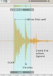
Yes, the frequency and number of pulses will have to be a compromise between the pipe diameter and the minimum expected water depth and the ease of filtering out the expected echo return. The burst length always needs to be shorter than the round trip time-of-flight time for the shallowest depth, in my case around 8m (4m depth x 2). I'm not sure yet, but think there's probably an advantage in having a specific frequency "ping", rather than just a pulse, if only to make detection easier.

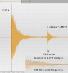
In theory, I could increase the frequency of the burst above 300Hz, I'm sure. As long as the wavelength remains significantly longer than the well liner inside diameter, then there should be almost no interference from wall reflections. With my 119mm liner inside diameter, that's a frequency of just under 2.8 kHz. I chose 300 Hz as it's roughly 1/10 of that frequency, to be on the ultra-safe side, but I could probably usefully increase the frequency of the tone burst to around 1 kHz, and still remain reasonably free from wall reflections.

1 KHz is 0.33m per cycle, so 10 cycles would be 3.33m, which is less that half the total distance for the round trip down and back to the water surface at the shallowest depth I'm likely to ever get.

I think some more experiments are needed, as increasing the frequency would definitely improve the efficiency of the small waterproof speaker a fair bit. Be able to use a burst of 1 kHz as the pulse would also make the filtering simpler and reduce the length of the pipe that I intend to use a as an acoustic filter at the well head.
 

Jeremy Harris

Senior Member
How about a 100 watt Piezo Horn Driver, you could really give it a kick with that.
What I've found so far, is that you don't really need much power at all to get a usable return echo. A bit of pipe is pretty good at ducting sound with low losses, so a pretty low power ping should work OK. Not sure about those with really deep wells, maybe they will need a bit more power, but I'm hoping that I can get away with a ping that's barely audible at the well head.
 

techElder

Well-known member
Jeremy, the most ideal "ping" is one where you push the speaker cone to its maximum swing and "let go" of it. Let it swing at its resonant frequency, so to speak, but damp it down to one or two cycles depending on how far the echoes have to travel. You can get away with 300 Hz. if that is near resonance, but it isn't necessary to get that complicated.

In other words, you could drive the speaker with a capacitor coupled circuit. Just bang it with a quick pulse and control the generated wave with the damping circuit on the speaker.

PS. Or you could do it like the old Polaroid system (might still be around) where they used a piezo crystal for the transducer, adjusted the receiver gain over time and even used multiple frequency pulses.
 

Jeremy Harris

Senior Member
That's an idea, just apply a pulse of DC to deflect the coil as far as it will go, then remove the power and, perhaps, add a resonant tank circuit tuned to the mechanical resonance of the speaker coil to produce the transmit signal. It has the advantage of not needing much drive power, I think, just enough to get the coil to deflect to it's maximum and no more.

I'm just working on the hardware for now,cutting bits of plastic sheet and getting things ready to bond them into the small sealed ABS box I have. A boss once told me years ago that the best way to start any project was to get the case and enclosure built before you start, as psychologically you're then better equipped to finish it. I've found it to be good advice over the years!
 

techElder

Well-known member
That's an idea, just apply a pulse of DC to deflect the coil as far as it will go, then remove the power and, perhaps, add a resonant tank circuit tuned to the mechanical resonance of the speaker coil to produce the transmit signal. It has the advantage of not needing much drive power, I think, just enough to get the coil to deflect to it's maximum and no more.
In ultrasonic inspection equipment, the an SCR is actually the driver with a capacitor to couple to the transducer. Of course, those are piezo-type transducers and the drive is at 400 volts to get the highest resolution possible at high megahertz frequencies. Not in your case, though it probably will work.
 
I apologize to break in on thread this late, but this is a very hot topic, and I know the well monitoring problem well (sorry..) from Tanzania, where supply of fresh water can be a big problem. In both of "my" wells (Dar es Salaam and Bagamoyo), we use the basic manual method (load and rope), but I would welcome something automatic which communicates to my cell phone.
Although acoustic methods seem tempting, I thought - but never tried - that if one could vary the pump rpm, one could find the minimum voltage/rpm to start the flow of water, and that would reflect the pressuse difference and thus the level of water in the well. Have anyone of you guys tried or heard of that?
 

edmunds

Senior Member
Just an idea from looking at the pressure gauge from a washing machine I just replaced...

What if you bought a thin plastic tube, like they use in aquariums and similar places and connected it to a pressure sensor like this on top of the well. The other end of the tube would have to go to the minimum water level you are interested in measuring. Rising and falling water level would create different and proportional air pressure in the tube that would change the reading on the output of the sensor.


Good luck,

Edmunds
 

techElder

Well-known member
I've never seen a submersible well pump that you could "vary the rpm" with. Most use AC motors designed for the local grid connection.

Perhaps there is a DC well pump that you could find to do that with.
 

Jeremy Harris

Senior Member
I apologize to break in on thread this late, but this is a very hot topic, and I know the well monitoring problem well (sorry..) from Tanzania, where supply of fresh water can be a big problem. In both of "my" wells (Dar es Salaam and Bagamoyo), we use the basic manual method (load and rope), but I would welcome something automatic which communicates to my cell phone.
Although acoustic methods seem tempting, I thought - but never tried - that if one could vary the pump rpm, one could find the minimum voltage/rpm to start the flow of water, and that would reflect the pressuse difference and thus the level of water in the well. Have anyone of you guys tried or heard of that?
It might work with some simple pumps, but some (like my Grundfos) have clever electronics built in, the idea being to both give the pump a "soft start" and to allow reduced power consumption plus protection from dry running. Also, must non-intelligent pumps seem to use a capacitor start/run motor, either with the capacitor at the well head or pump room, or, in some cases, built in to the pump motor.

If you had a standard "dumb" two/three phase motor and could hook it up to a variable frequency drive, then I think what you propose could work. Grundfos have something similar with their electronically controlled pumps, that use power line signalling to tell the pump what speed to run at, with a well head, or pump room, constant pressure controller. Getting some indication from that could do what you want, but those Grundfos pumps are pricey!
 

Buzby

Senior Member
Hi Jeremy,

It's gone a bit quiet on this thread, how are you getting on ?.

If you are still interested in the 'organ pipe' idea, here is a little tool I knocked up to generate low frequency sine waves.

Code:
'============================================================================================
' Low frequency sine wave sweep generator using DAC 
'============================================================================================

#picaxe 28X2
#no_table
#no_data
'#terminal 76800

symbol DAC_PIN = A.2	' Fixed pin for DAC output
symbol dval = w0		' Pause delay value for selected frequency
symbol srate = b2		' Sets sample rate, determines purity of wave shape vs maximum frequency.
symbol fsel = b3		' Frequency selector
symbol icount = b4	' Interrupt counter

symbol icountmax = 15	' Interrupt counter divide value, determines speed of sweep in 0.25sec units.

' Constants for frequencies when srate=1 
' Double frequency when srate=2, quadruple freq when srate=4, octuple when srate=8
' Note, resolution is reduced as srate increased > 1 

symbol  p1Hz = 2970
symbol  p2Hz = 1420
symbol  p3Hz = 897
symbol  p4Hz = 639
symbol  p5Hz = 486
symbol  p6Hz = 382
symbol  p7Hz = 307
symbol  p8Hz = 253
symbol  p9Hz = 210
symbol p10Hz = 175
symbol p11Hz = 149
symbol p12Hz = 123
symbol p13Hz = 103
symbol p14Hz = 85
symbol p15Hz = 70
symbol p16Hz = 57
symbol p17Hz = 46
symbol p18Hz = 36
symbol p19Hz = 27
symbol p20Hz = 18
symbol p21Hz = 9

'============================================================================================
' Code starts here 
'============================================================================================

setfreq em64		' Use external 16MHz xtal with 4x multiplier 

gosub setupram		' Setup the sine wave table in scratchpad RAM

low DAC_PIN			' Make the DAC pin an output

dacsetup %10100000	' Set DAC ouput to external pin, Vref is supply voltage

settimer t1s_16		' t1s_16 is 1sec at 16MHz, but 0.25sec at 64MHz

srate = 1			' Sets sample rate, determines purity of wave shape vs maximum frequency.  

gosub interrupt_enable 	' Enable interrupts from timer ( Comment this out to run only at inital frequency )

dval = p10Hz 		' Initial frequency

' Main loop
' ---------
do
	ptr = ptr + srate & $FF ' increase ptr by current step value, limit to 255
	daclevel @ptr 	' Set DAC output level
	pauseus dval 	' Delay according to selected frequency
loop	' End of main loop

'============================================================================================

interrupt:
	' Interrupt is called every 0.25sec

	' interrupt counter, only process every icountmax interrupts, determines sweep rate.
	inc icount
	if icount >= icountmax then 
		
		icount = 0

		' frequency selector
		if fsel > 20 then : fsel = 0 : endif
		lookup fsel,(p1Hz,p2Hz,p3Hz,p4Hz,p5Hz,p6Hz,p7Hz,p8Hz,p9Hz,p10Hz,p11Hz,_
		             p12Hz,p13Hz,p14Hz,p15Hz,p16Hz,p17Hz,p18Hz,p19Hz,p20Hz,p21Hz),dval
		inc fsel 
		
	endif

interrupt_Enable: 	' Enable or re-enable interrupts
	setintflags %10000000, %10000000
	timer = $FFFF
	toflag = 0
return
	
setupram:
	' Populate RAM with sine wave
	for ptr = 0 to 255
		lookup ptr, (16,16,16,17,17,17,18,18,19,19,19,20,20,21,21,21,_
			      22,22,22,23,23,23,24,24,24,25,25,25,26,26,26,27,_
				27,27,27,28,28,28,28,29,29,29,29,29,30,30,30,30,_
				30,30,31,31,31,31,31,31,31,31,31,31,31,31,31,31,_
				31,31,31,31,31,31,31,31,31,31,31,31,31,31,31,30,_
				30,30,30,30,30,29,29,29,29,29,28,28,28,28,27,27,_
				27,26,26,26,26,25,25,25,24,24,24,23,23,23,22,22,_
				21,21,21,20,20,20,19,19,18,18,18,17,17,16,16,16,_
				15,15,15,14,14,13,13,13,12,12,11,11,11,10,10,10,_
				9,9,8,8,8,7,7,7,6,6,6,5,5,5,5,4,4,4,3,3,3,3,2,2,_
				2,2,2,1,1,1,1,1,1,0,0,0,0,0,0,0,0,0,0,0,0,0,0,0,_
				0,0,0,0,0,0,0,0,0,0,0,0,0,0,1,1,1,1,1,1,2,2,2,2,_
				2,3,3,3,3,4,4,4,4,5,5,5,6,6,6,7,7,7,8,8,8,9,9,9,_
				10,10,10,11,11,12,12,12,13,13,14,14,14,15,15,16),@ptr
	next
return
If you run this into an amplifier and speaker you should be able to hear the resonance.

The code is a bit basic, it just sweeps from 1Hz to 21Hz over a few seconds then repeats.

What it really needs is some up/down controls to allow tweaking the frequency on demand, but I'll leave it to you to add these if needed.

Cheers,

Buzby
 

Jeremy Harris

Senior Member
Thanks for giving me a gentle nudge - much needed!

I've been diverted over Christmas into redesigning and relocating our whole house data acquisition and logging system. This was just a single unit, with a load of sensors connected directly to it, that sat in an out-of-the way location, close to where I could easily get the sensor cables to it (most of the sensors are DS18B20s, but there are also humidity sensors and now a CO2 sensor as well). A while ago I converted this unit so that the RTC is corrected and reset every night (at 02:03, to catch the hour change with BST/GMT switch overs) using a remotely mounted MSF clock to get a decent time standard, one that adjusts for BST and GMT.

This has worked well for a couple of years, but SWMBO likes looking at the accurate clock display on the front of the unit, and it's tucked away where this isn't easy. So, the Christmas break project was to take everything apart and re-jig it.

I now have a hall mounted 20 x 4 line LCD display and sensor unit (with one of the nice laser cut bezels from Rev Ed) that displays outside temperature, indoor relative humidity, indoor CO2 concentration and the day, date and time on the lower line. This has a 20M2 driving the display, an IR CO2 sensor, a DS18B20 for room temperature and a humidity sensor.

Where the old logger was located, under a worktop in the utility room, I now have just a data acquisition box, with a 14M2 in it and no display, that just measures a load of sensors and transmits the data via a serial link (at TTL level......................) to the relocated logger. The logger (which stores data every 6 minutes to an SD card) also uses a 14M2 and an OLED 20 x 4 line display, but now just takes serial data from both the hall mounted unit and the utility room units, and logs it. It also transmits the outside temperature and the RTC data to the hall mounted unit. I've stuck this away upstairs in the services room we have, where the electrical switchgear, hot water system and heat recovery ventilation system is located.

It's taken longer than planned because of the limitations of sending serial data at TTL levels. It took me a while to work out what the cause of the odd problems were, as I was happily sending TTL level data on one link, at 2400 baud, over a 10m length of cable. However, another similar length of the same cable point blank refuses to work reliably at 2400 baud, something I've literally worked out in the past half hour. As I need clock rates of 16MHz on some of the Picaxes (to get reliable 9600 baud comms with the SDLogger and the CO2 sensor) I'm now in the process of re-writing the code to slow the clock speeds right down so that I get nice, low, baud rates for the hall display and data acquisition unit, then speed them up again for the timing critical stuff.

It's taken me far more time than it should have done to resolve this - it comes from having quickly got one bit working over 10m of cable and then doing that most dangerous of things, assuming it would ALL work over similar lengths of cable. I'm about to try it all at 600 baud, to see if that cures all the problems, but as none of it is really time-critical (the time is only displayed to the nearest minute) then I could go lower if needed.

So, the bottom line is that faffing around with this has meant I've done nothing at all with the borehole sensing - but thanks very much for the code snippet, I shall get back to it as soon as I've got the other stuff working, screwed all the boxes back on the wall, and touched up the paint................

(I've just down a quick count, our house now has around 11 Picaxes on all the time doing stuff!)
 

Jeremy Harris

Senior Member
I can imagine your house, Jeremy. Is there a traffic counter on the stairs?

Happy New Year.

Peter
There's more on the house here: www.mayfly.eu if you want to see what it looks like. Some of the stuff in that blog is outdated now, and I'm in the process of updating it by adding new entries describing what we finally ended up with.

I also underestimated the number of Picaxes in the house! The total is:

2 off 14M2s, 1 off 08M2 and 1 off 20M2 running the data acquisition and SD card parameter logging ( 4 Picaxes in total as a system, including the 08M2 that runs the MSF radio code clock)

2 off 08M2s and 2 off 20M2s running the energy monitoring and display, plus the excess PV electricity diverter that gives us hot water (so 4 Picaxes in total looking after energy measurement and control).

2 off 08M2s in two separate electric vehicle charge points (EVSEs) to provide the control signalling needed to operate electric car charging to the J1772 protocol (so 2 Picaxes dedicated to the two EV charge points, one by the garage one at the other end of the drive)

2 off 14M2s and 1 off 08M running the sewage treatment plant alarm system (with radio link to the house) and providing a 66% duty cycle timer for the aeration pump (30 minutes on, 15 minutes off) to reduce energy use (so 3 Picaxes in total)

4 off 08M2s running remote radio switching for control of external gates (so 4 Picaxes in total)

1 off 08M2 running a 20 second pulse switch to operate a solenoid valve whenever our borehole pump switches on, to flush the aeration tank of ferrous oxide particles (so 1 Picaxe there).

1 off 08M2 connected to a Doppler microwave sensor and a radio link, plus another 2 off 08M2s connected to radio transceivers and relays, to detect intruders and turn on two solid state CCTV recorders connected to 2 cameras (so another 3 Picaxes)

That brings the current total to 21 Picaxes in the house and there are plans for several more, as I want to replace 4 time switches with a radio linked programmable timer system, with the clock set by the MSF radio code receiver. At a guess this means at least 5 more Picaxes on the way, maybe more, as the master timer control box may well need more than a single Picaxe to handle things. There are also portable things with Picaxes in, not mentioned above. I have a portable air quality monitor that has a 20M2 in, a portable MSF time code receiver (with cable interface for resetting the RTC on other things) with an 08M2 in, my electric bikes each have at least one Picaxe in (one has two, the other has one) and there are probably a few more things around that I've forgotten!

Happy New Year, everyone!
 

Willie...

New Member
THIS TOPIC is what I have been searching for! Wow! It's been difficult to find!

OK, my situation is similar to this discussion, except that I have a DEEP borehole well! (over 200 feet, 62 meters)

My water level ranges anywhere from maybe 50 feet (15 meters) when the well is FULL to over 200 feet (62 meters) deep when EMPTY. I can VERY EASILY hear the echoes to the water from the well head if I make a CLICK. (Clap my hands, tap the pipe, etc.) I can clearly hear the echo. When the well is full, the echo is short, approximately 150 milliseconds (round trip.)

I measured the time by recording the sound with my phone, then opening the recording in my audio editor software on my PC, then highlight the distance between CLICK and 1'st echo. Deceptively simple. :)

When the well is empty, the pump controller shuts down, to prevent dry-running the pump. At the empty depth, the echo is 389 milliseconds. All I want to do is use my PICAXE to pulse a speaker once to make a "CLICK!" then start a timer, and wait for that first echo. Once that is done, some BASIC (pun intended) math should give me the well water depth. To make things even simpler ;) I would like to have the PICAXE calculate the depth as a percentage, so 150 milliseconds (or less) would be 100% full. 389 milliseconds would be 0%.

I am a very skilled electronics tech, and can build/design many kinds of analog circuits, so that part is fairly easy for me. I just need some help coming up with the CODE to calculate those echoes. :)
1) "CLICK!"
2) start timer
3) receive echo pulse
4) do math
5) display result

Ideas? :) THANKS in advance!
 

premelec

Senior Member
Likely you need to exclude pump running sounds and drip sounds so best take a listen before going too far... don't know if SRF ultrasonic sense units can do skinny bore work... in any case I would check several readings in a row for consistency before accepting the reading. There are commercial "Pump Saver" units that check the pump currents and shut down or retry [we use one...] - good luck with it.
 

inglewoodpete

Senior Member
... don't know if SRF ultrasonic sense units can do skinny bore work... in any case I would check several readings in a row for consistency before accepting the reading
I did some experiments with ultrasonic distance sensing in a 100mm (4") PVC pipe a few years ago. Unsuccessful! After about 500mm, there is such a tangle of echoes that false triggering was almost constant.
Echo received at 1400mm:
Sonar1400mm_N445_S861_LR.jpg

I was not sensing the depth of water but determining the distance to an object suspended in the pipe on a cable. The (very successful) solution was to mount the ultrasonic transmitter on the suspended object and the receiver at the end of the pipe. Rather than relying on the confusing echoes, the measurement was from Tx to Rx.
 

AllyCat

Senior Member
Hi,
highlight the distance between CLICK and 1'st echo. Deceptively simple. :)
.... I just need some help coming up with the CODE to calculate those echoes. :)
A very interesting project and IMHO quite possible to do even with a PICaxe (or maybe particularly with a PICaxe). ;)

The timing, "math" and display are all well established and you should find particular (coding) assistance in the CODE SNIPPETS section of the forum. The forum "Search" is still quite primitive and you may do better with a "Global" Google Internet search, including "PICaxe" as a keyword. For display, possibly a classic 1602 (16 x 2 characters) or 2004 (20 x 4) LCD or OLED display, or the tiny current favourite SSD1306 OLED "graphical" displays for a simple "historic" presentation (hours through to years)? But I note that the power supply and a "User Interface" are not on your coding list?

IMHO the echo detection is potentially the "difficult" part of the project : don't under-estimate how dificult it can be to code something that the (human) brain finds trivial. Firstly, do you mean "Click", or might "Pop", "Ping" or even "Tick/Tock" be more appropriate? But personally, I would definitely use "audio" (sound) in preference to Ultrasonics, if only for the same reason as working with visible (white) light in preference to Infra Red - in that it's easy to "see" (hear) the conditions under which the sensor is (or isn't) operating.

However, my thoughts immediately turned to an "Organ Pipe" solution (maybe from originally reading this thread, I haven't looked at it again now), i.e. putting the air column in the pipe into resonance. Such a method automatically incorporates the probably essential averaging and filtering required for the "audio" processing. I believe the fundamental resonance is wavelength / 4 , with much the same theory as (monopole) radio antennas, i.e. reflections and phase inversions happening at "short-circuit" and "open-circuit" terminations. In principle, you would kick the pipe into resonance with Clicks/Pops spaced at the resonant frequency, either by feedback (hence possibly Tick/Tock = +/- ) or simply "sweeping" the frequency and looking for a peak. I'm not sure what transducer might be used, but probably a conventional (8 - 32 ohms) miniature loudspeaker?

In this case the "audio" frequency may be around 1 Hz (i.e. ~1000 times slower than normal audio) so the analysis/calculation might take literally minutes, which is one reason why I think this could be well-suited to a PICaxe. Of course the question arises: what "microphone" works well at 1 Hz, to which my answer is "A barometer". Several have been discussed in the Snippets section, but the current favourite is probably the tiny, low cost BMP280 (on a breakout board, not the naked chip!) which can interface with the PICaxe directly via just the two-wire I2C bus. It can detect air pressure differences equivalent to a few cms of altitude*, sampling the data at up to around 100 Hz, which seems well within the requirements of this project. Don't be disturbed by the apparent (and actual) complexity of the BMP calculations, which are required to give absolute pressure, but you only need to detect pressure differences which can come directly from its raw ADC converter (20 bits). *Or "floating" one on the water together with a (wireless) transmitter might be an alternative, but not very sensible, alternative. :)

Practical experience is really the most important factor, but Jeremy's "mayfly" link looks incorrect now? I don't believe he's been "active" on this forum recently, but I notice that he did "visit" it yesterday, so perhaps will contribute if he has anything to add.

Cheers, Alan.
 

Buzby

Senior Member
I've not tried this, but it looks like it might be good for analysing bore hole resonances, before developing a measuring device.

It's a real time frequence response measuring programme that uses pink noise instead of a swept frequency.

It is really aimed at audiophiles, so I don't know if it will have a low enough 'bottom end'.

( Regarding the 'click and echo' method, I can definately confirm that after a few metres the returned echo is just a mush of noise. Very difficult to sort the wheat from the chaff. )


premelec

Senior Member
FWIW a reliable and likely good way to implement a solution is to run a small bore pipe down to the pump top and use compressed air at the well head forcing bubbles at the pump top to determine the water depth above the pump with a pressure transducer on the compressed air needed to make bubbles down below. Likely a small compressor such as found in auto blood pressure cuffs would work.
 

Willie...

New Member
Some thought-provoking replies, here. :) First, to clarify, ultrasonics absolutely WILL NOT work in this case. The distance is MUCH too great, (Over 200 feet (62M) when empty) AND the pipe and bore hole totally absorb high frequencies. A "CLICK" that's rich with high frequencies (has a "sharp" sound, like clapping hands) comes back as a dull thud. Meaning, only the lower audio frequencies are making the round trip from the top, to the water, and back. It would also be nearly impossible to set up something capable of single-digit Hz, using anything but long-throw woofers! ;) No, the "Click!" and wait for echo method would be best, simply because the first echo is VERY easily discerned both audibly, AND on a waveform display. I've attached a picture of the "empty" well echo. Because the echo contains a fairly low frequency (maybe 400Hz?) the echo is VERY clear and could be easily detected by a normal microphone & op amp/comparator to give the PICAXE a clean pulse input. The pump already has a controller, so no need to worry about that. :) I definitely don't want to lower anything down into the well, either... would make pump replacement VERY problematic! Again, this well is over 200 feet (62M) deep! I have assisted the well crews with TWO pump replacements since we bought this house in 2000. It takes THREE MEN to pull that thing up!!! :eek: (I just Googled it, and it would take nearly 100PSI to "bubble" at 150 feet depth!)
 

Attachments

Last edited:

premelec

Senior Member
OK I missed actual head of water and you do not want to use bubbler [I get about 65PSI if I understand correctly .44 PSI per foot]. I have pulled deeper pumps in the good old days of iron pipe... that water & pipe ARE heavy! As I mentioned my current well uses a Pump Saver unit which checks operating current for suck out, dead head, etc. I expect your main concern would be running dry and that could be discerned by flow and a delay to allow well to refill - and perhaps timing between suck outs auto lengthening the delay... Good luck with it - home water systems are wonderful and educational... A simple flow detector can be made with two identical thermistors in the stream - one heated with some current and other not... or a pressure transducer...
 

Willie...

New Member
Fortunately, the pipe is actually a slightly flexible PVC-like material. It is pulled by using a pulley system at the well head, then three guys do a tug-of-war across the property, pulling over 200' of that pipe out of the ground, until the pump is finally lifted to the surface. As I mentioned, I have assisted the well workers with the pull... to save the expense of bringing in another guy! ;) However, as I get older... that's getting more difficult! :( Anyway, the pump-saver has been working perfectly all along. It senses the current of the pump motor, which drops sharply when it starts to draw air. That trips the shutdown. I haven't timed the re-start timer, but it's a fairly long time. (An hour? Not sure.) However, the way the pump works requires the water to rise some unknown distance ABOVE the pump, before it will again start pumping. Because the recovery rate of this well is rather slow, and it varies, there's no way to know... until the re-start activates, and the pump actually starts pumping. That often takes hours, and more than one re-start. So, I want to measure the water... just for reference, so that I can do a "sounding" and know that I have, say, 33% water remaining, and plan accordingly. Thankfully, we have a large pressure tank, so even when the well "goes empty", we can "ration" that water to last as long as several days. So far (thank the LORD) we have only had to "ration" for a day at most. I can tell by the behavior of the pump, sounds of the check valve, and the current draw, a very rough guesstimate of water remaining. If the well is FULL, the check valve chatters clearly and distinctly, and the pump draws slightly more current. (I have an arbitrary scale, home-made "clamp-on" current meter on the system to watch it.) I also have 21 years of experience with this thing. :) I know it pretty well. (Pardon the pun.) ;)
 

Willie...

New Member
BTW, a follow-up thought on the heated vs unheated sensors... I worked with an AM broadcast transmitter years back, that used a similar concept to ensure that there was sufficient air-flow to keep the transmitter cool. It used a transistor with a small heat sink in the air intake path. If it wasn't getting enough airflow, the temperature would rise, the current would change, and trigger a safety shut-down of the transmitter. Flow-rate in this case would be a very difficult thing to set up. The operating PSI of the tank ranges from 50~70 PSI. I don't want to be drilling holes into the pipes feeding it. :)
 

AllyCat

Senior Member
Hi,
..... the first echo is VERY easily discerned both audibly, AND on a waveform display. I've attached a picture of the "empty" well echo. Because the echo contains a fairly low frequency (maybe 400Hz?) the echo is VERY clear and could be easily detected by a normal microphone & op amp/comparator to give the PICAXE a clean pulse input.
Remember that "the computer" (PICaxe) may be working with purely binary signals (Yes/No) and is only as "intelligent" as you make it in your program. Firstly, the decay of the "click" has a larger amplitude than the "echo" until at least 4 horizontal divisions, so you'd need to "gate" (ignore) any microphone signal for the first 5 divisions, which appears to impinge on your "Well Full" delay for a 50 feet measurement? Of course the echo should be larger at that point, but it implies that you need some form of adaptive/variable gain/threshold control. Secondly, here is an "alternative" version of your screenshot, which also might look "plausible" (particularly to a dumb computer algorithm) but is the WRONG delay. ;)

PreEcho.png


Personally, I still consider myself primarily a trained Hardware Engineer, but as electronics components got smaller and my eyes older, I'm quite relieved that I (partially) crossed the water into Software Design. IMHO the Microchip/PIC assembler Instruction Set is "horrible" (so we must be grateful to Rev Ed for PICaxe Basic) but the PIC "silicon" Hardware features have always been commendably good, so we should try to use them. ;) Also, it's generally much "Easier for Us to help You" if the hardware characteristics are known to us and potentially under our (software) control. And the PICaxe Editors' software simulator shouldn't be overlooked.

Now to consider the hardware design: You might even use the Loudspeaker as a "Microphone", but that certainly would need an amplifier. I believe Electret (capacitor) microphones may give quite a large signal output; particular problems with needing an amplifier is that its "overload" capability may cause issues (particularly ac bias-level shifts) and/or a variable gain control be required. Then you need an "Envelope Detector", in principle just a Diode, Capacitor and a couple of Resistors, but the time constants need to be optimised and the (variable) forward voltage drop of the diode can be quite significant if signals are small. Then, ALL current PICaxes have at least one internal Comparator, with the advantage of a software-adjustable threshold level (DAC). But for the time delays here, a continuously-polled ADC measurement (less than 1ms) may give the program more useful "information" (and control) than a simple 0/1 input.

But, as I often say, it's really down to the "Requirements Specification": A User-Friendly "Display that hangs on the wall and accurately shows the water level 24/7" would be a more challenging task than a "Flash a LED warning, to go and see if there's a possibility that the pump might be getting into trouble". ;)

Cheers, Alan.
 

Willie...

New Member
OK, here's a bit more detail. :) The echoes of various depths (only comparing FULL & EMPTY here) are 630 Hz bursts. The CLICK is a tap against the pipe with the wellhead cover. (All metal.) Ideally, I would definitely use a speaker and a microphone. The PICAXE creates the CLICK (just a simple pulse) waits 150ms, then starts the timer, until the pulse is received. Using hardware op amp and comparator, will give me the square pulse needed to stop the PICAXE timer. The rest would be a matter of using the right algorithm to calculate the range of delay, which is pretty much fixed. Any echo less than 160ms from "CLICK" means that the well is FULL. An echo of 380ms means the well is EMPTY. Everything in between can be scaled from 100% down to 0%. I have no way to safely PERMANENTLY mount such a sensor outside, at the well, so this will be a device I carry out there, open the well, set the "box" on top, and press a button... then read the display. :) At this point, it's just a "rough guess" by lifting the cover, then tapping it against the pipe, and listening to the echo. (Or record it on my phone, then analyze it on the PC.) Would be nice to just read a display "55%". BTW, I've pored through the CODE SNIPPETS section here on the Forum, and found nothing even close to what I need here. :( I'm not asking "please write my code for me", as that's selfish and rude. :) I only need some ideas to get me going in the right direction with this. :)

THANKS IN ADVANCE! :)
 

Attachments

Jeremy Harris

Senior Member
Sorry for the absence of a conclusion to this project!

I couldn't get a sound-based system to work, for the reasons others have given regarding the very dirty return signals. I used a "bubbler" system for a time, that used a small air pump and pressure sensor to measure the back pressure, but the small compressor packed in after a short time. The system I have now is a bit crude, but seems reliable. I have a string of conductive type water detectors down the well, the sort intended for use to detect flood water in cellars (these: https://www.tanealarm.com/products/accessories/tane-ws-1/). I have them spaced at half metre intervals and have found that's good enough to be able to monitor changes. In practice I've found that there is barely any change in the level at all. It drops by about a metre when the pump is running, but almost immediately comes back up to the ~11m below ground level resting level. The well itself is actually 53m deep, but we now have the pump only about 25m down, as we have had to change it once and it's a lot less work hauling 25m (~82ft) of pipe and pump up than it was pulling about 50m of pipe and pump up.
 

premelec

Senior Member
Willie - despite what Jeremy says it looks from your oscillograph traces you could come close enough for some practical use... some analog or DSP processing of the signal could help or just a peak capture circuit for first echo... Suggest trying different rapping than speaker to see what that does to the signal - i.e. tap with hammer [could be solenoid]. Any way if you solve it let us know... BTW there are ultrasonic flow methods that don't require contact with liquid that can detect flow.. perhaps doppler shift though I don't remember specifics. You mention age/ability - I am 85 and have large loss of ability from heart and lung troubles over last year... it is no fun... keep in shape... ;-)
 

Willie...

New Member
Sorry for the absence of a conclusion to this project!

I couldn't get a sound-based system to work, for the reasons others have given regarding the very dirty return signals.
Interesting! I noticed also that the return echo gets "dirtier" when my well is full... but it really doesn't matter, because if the echo is less than 160 milliseconds, I have more than enough water. :) My well is nowhere near as good as yours. :( If we use too much water in too short a time, the pump controller detects the fact that the pump has stopped pushing water, and it shuts off. It takes a number of HOURS for the water level to rise enough for the pump to "grab hold" again, and start pumping. Fortunately, our pressure tank is large enough to hold at least several days supply of water, if we ration it.

Yet my neigbor, who's well is no more than 60 feet away (19 meters) NEVER RUNS OUT OF WATER! His well seems to be a lot like yours. If you look down the borehole, you can almost ALWAYS SEE the water. No such things with mine... you HAVE TO use an echo... or something you lower into the well. I VASTLY prefer the former. ;)
 

Willie...

New Member
Willie - it looks from your oscillograph traces you could come close enough for some practical use... some analog or DSP processing of the signal could help or just a peak capture circuit for first echo.
I probably could build something like a "twin-T" audio filter, tuned for 630Hz, because that is the frequency that returns from the echoes at any depth. It is a CLEANER 630 Hz signal when the well is low, and has more noise & harmonics with the full well. Still, the echo is very definitely clear and distinct enough, that a few op amps will suffice to pick it up and give the PICAXE a clean pulse.
 

AllyCat

Senior Member
Hi,

Hmm, I'm surprised that Jeremy couldn't get an audio system to work because he seemed to be on the right track (200 Hz. "Ping", etc.) using a principle that's commercially available (and of course used for underwater "Sonar" depth sensing). The reason is possibly that a PICaxe is inherently too slow to "analyse" audio signals, which I why I've tried to steer towards an Ultra Low Frequency (~1 Hz) resonance system which a PICaxe could (more) easily detect. Note that it doesn't need a Low Frequency Loudspeaker, in the same way that a clock pendulum resonating at 1 Hz (or 1/2 Hz) is energised just by the "Tick" and "Tock".

But back to the current concept; Firstly, I suspect that there's an enormous difference in the amount of energy introduced into the pipe (and air column) by hitting it, compared with a Loudspeaker. So it could be that you should be designing a magnetically-driven "hammer" for the pipe, which might generate a reasonably good "burst" of constant-frequency tone. Secondly, the waveforms are "Envelopes" which are almost impossible to (directly) detect with a PICaxe: If you use IF pin = xx or READADC pin then it is a random chance whether the program will "see" an instantaneous High or Low part of the waveform. Thus you need either a Hardware "Envelope Detector" or to measure the pin at least ten times and compute an average, which is not ideally suited to a PICaxe (but not necessarily impossible). Or perhaps a simple Peak Detector or a Threshold Detector + Latch , if you're confident that there will be no spurious "spikes" of sound during the measuring period.

You haven't specified which PICaxe you're planning to use, but PICaxe Basic doesn't really offer a "timer". The "normal" method of measuring time intervals is PULSIN , which measures the time between a rising and falling edge (or vice versa) on a single input pin, but can do nothing else during that period. There are other possibilities such as a "counting" software loop (but calibration is difficult) or accessing one of the hardware counter-timers, but the programming is not trivial. Also, I suspect you may need a "decaying" threshold during the measurement period to compensate for the lower amplitude of the more distant echos.

However, if you can design hardware to reliably deliver logical pulses or edges which correspond to the "click" and the "echo" and describe a "strategy" using the available PICaxe Basic instructions, then we should be able to devise a program to measure the time delay. But you should plan to make multiple measurements and have a strategy to "sort the wheat from the chaff" if they don't all agree. As I've indicated before, it's easy to look at a 'scope waveform and decide if it's "good" or "bad", but much more difficult for a program to do the same thing. From then on, the calculation to a Depth and/or Percentage value should be quite trivial, with snippets available if necessary for the initialisation and presentation of data on most types of display.

Cheers, Alan.
 

Willie...

New Member
Thank you, Alan ("AllyCat") for that detailed reply. :)

I do, indeed, plan to use external hardware to detect and convert the analog pulses into a squarewave (logic level) pulse for the PICAXE. I have used a number of different sources for the sound of the "CLICK"... from clapping my hands, to tapping on an empty plastic container. *ALL* of those methods produced a VERY CLEAR echo, both audibly AND on the screen of my audio editor/analyzer software. Thus, a simple "CLICK" from a speaker will more than suffice to create an echo, especially if the "click" is a burst of several cycles of 630 Hz. :)


This is a crude "flowchart" of what I want to do with the Code... (I hope this helps.) 20X2 Chip

:START
(WAIT for button press)
(SEND CLICK) 'Just pulse a speaker with a short 630 Hz burst. the "Tune" command should suffice.
(PAUSE 150ms)
(START TIMER, 1ms increments) ' A 1KHz clock freq on a timer will be sufficient
(LOOK for logic pin to change state) ' This is handled by external analog hardware; op amps.
(STOP TIMER & read value) ' Values will range from about 10 (or less) up to less than 400.
(COMPUTE value from 0 to 100%, and send it to LCD.)

GOTO START

I already have my LCD working... this little display is over 30 years old! Still works 100%! :)
Of course, I HAD TO put "Hello World!" ;) 5 seconds after that, it clears and writes all "solid block" characters, then clears the display, and loops back to write the chars again, with a .5 second delay. The purpose being to "exercise" the LCD segments to improve contrast. I'm just glad it still worked after all these years in my parts bins. :)
 

Attachments

premelec

Senior Member
Not clear what 630Hz has to do with what you want to measure - Just a DC hit to the speaker should produce a good echo. Simple rectifier and RC short time constant filter on microphone end could work ok. - you can use the speaker as a receiver with appropriate amp. Maybe the 630 Hz is a small speaker resonance... ?
 

inglewoodpete

Senior Member
Not clear what 630Hz has to do with what you want to measure - Just a DC hit to the speaker should produce a good echo. Simple rectifier and RC short time constant filter on microphone end could work ok. - you can use the speaker as a receiver with appropriate amp. Maybe the 630 Hz is a small speaker resonance... ?
Perhaps 630Hz is the dominant echo or some strange resonance (or more likely, non-resonance) of the bore casing. Wavelength of 630Hz in air is 546mm at sea level and 20 degrees C.
 

AllyCat

Senior Member
Hi,
.... this will be a device I carry out there, open the well, set the "box" on top, and press a button... then read the display........ Would be nice to just read a display "55%"
There's a great temptation (for us) to Over-Design a project, so to start, perhaps we Keep It (even) Simpler. A "box"/PCB which you sit on the top of the wellhead and hit the pipe with a little "hammer" (a teaspoon or key, etc.). Perhaps use (intentionally) different strengths of "click" and if the majority of displayed measurements are consistent then you have a "result"; If not, then the pessimists among us may be correct (or the optimists wrong). ;)

Is the 630 Hz perhaps the air resonance across the diameter of the pipe? I think it should be half-wavelength which I calculate as 10 inches, but perhaps half of that? However, I don't think you've shown us a screenshot of the fundamental wave, to see if we would also interpret it as 630 Hz. :) If using a Loudspeaker, I'm not sure if using this "natural" frequency is a good idea, I would be tempted to start at around 100 - 200 Hz., a frequency that a PICaxe program could potentially sample and decode using "software only" (apart from a microphone/transducer).

Personally, I don't use X2s, they do have a "timer" but with limited formal documentation. So you may need to start at SETTIMER and work from there. For 1 ms "ticks" it looks as if you would need a preload value of 65536 - 31 = 65505, but it could be easier to calibrate it directly in "feet" or even "%". I believe 100% = 220 ms so the preload could be 65536 - (31.25 * 2.2) = 65536 - 69 = 65467 ? You would then simply set the "starting delay" (e.g. PAUSE 150) to give "0" (%) when the well is full, or more probably "100" when empty, and then the display calculation becomes : timer = timer MAX 100 : Levelpct = 100 - timer. Incidentally, the M2s do have a "Timer1", complete with "Timer1 gate" hardware and latches on an input pin. But with a fixed 20 ms "tick" (overflow) , no accessible overflow counter and only by using Special Function Register commands.

Note that you don't necessarily need to "stop" the timer, just READ it, and then could wait for any further echos, to give more "confidence" or accuracy in the result. Also, all PICaxes have at least one internal Comparator which can be set to use the internal "DAC" to set its "threshold" level. So in principle, you could start the measuring interval at a "high" threshold and then after the PAUSE starting delay, gradually decrease the DACLEVEL xx to give increased sensitivity. This DAC has only 32 levels, so alternatively you might use an external capacitor for the threshold level, either driven from a PWM output (1024 equivalent levels) or by simply using the natural exponential decay of a parallel RC combination.

Cheers, Alan.
 

Jeremy Harris

Senior Member
FWIW, my initial system was just a cable reel with the cable marked off with distance markers along its length, a beeper fitted to the reel and a simple water detector on the end, with a brass weight to keep the cable taught. I'd lift the cap on the well and just unreel the cable down the well until the thing beeped, then read off the distance down to the water level from the cable marks. I still have this as a back up, as it's simple and pretty much foolproof. The well drillers had a commercial device that looked much the same, but had the wires embedded in what looked like a Fibron surveyors tape, and it was seeing theirs that gave me the idea to make one, using an old enclosed extension lead reel, that had room in the centre to take a battery and small beeper.
 

Willie...

New Member
I'm not going to use the PICAXE to try to measure the frequency. An external circuit is going to amplify, detect, and convert the echo into a single logic pulse. I only need to measure the time from CLICK to first echo. Regardless of the source sound I use at the well head, the ECHO is ALWAYS 630Hz. Why? I don't know... but it is. It is obviously some kind of "natural resonance" in the well... so I may as well work with it. :) If I "ping" a speaker with a few cycles of 630Hz, then I can expect that will yield a very "clean" echo, easily detected. That will be my first test with the actual PICAXE... get that 630 Hz "ping" to be the best length, for the clearest echoes.

I've owned this house for 21 years, now. Over this time, I have become all too familiar with all of the quirks of this well and the system connected to it. :) We're on our 3'rd pump... but when this one goes, I've already talked to the the well company, we're going to replace EVERYTHING down there... pump, pipe, safety rope, and wiring... it's all been there since I bought the house. (Except the pumps, as noted.) I just simply want a means to get a percentage of water remaining. 280ms is "Empty" and less than 150ms is "Full".
 

Willie...

New Member
UPDATE: I've gotten the following pulse test program written and working 100%. It is extremely simple, because I'm only testing the ability to generate a controlled frequency and number of pulses. According to the FFT analysis in my O'scope, this is 630Hz. :) Twenty cycles. It works beautifully! The duration of the pulse train is a bit over 30ms. I will probably end up reducing the number of pulses, as I experiment with this. I'll modify the code, below, to send a different number of pulses and do more in-depth audio analysis on my PC, to determine the "optimal" number to get the best echo.

Picture is of the O'scope screen, with a very simple R/C network (50 ohms to speaker, 10uf across speaker) being fed by the PICAXE chip. I may end up using some filtering and an audio amplifier, to get a sinewave to the speaker.

PS: Yes, I know I used a WORD variable there in the loop... originally, the value was 1000, to get a good reading on the scope. ;)

Code:
#no_data ; Save time, no EEPROM upload
#picaxe 08m2 ; Force compiler to proper chip mode

start:
sertxd("630Hz burst test for 08M2",cr,lf);ID chip program @ pwr-up

setfreq m16     'Set chip to 16MHz (Default is 4)

main:   

if pinc.3 = 1 then     'Wait for button press to start
   
    pause 2000     'Enough time to let go of button
   
    for w5=1 to 20     'send exactly 20 pulses of 630Hz, approx 50% duty cycle
        High c.1
        pauseus 200    'Very close to 630Hz
        low c.1
        pauseus 120    'Unequal due to loop timing
    next
endif

    pause 150     'Wait for echo (to be programmed)
   
'Timer, calculation, and display program will be written here...........

    goto main    'loop back to start
 

Attachments

AllyCat

Senior Member
Hi,
ECHO is ALWAYS 630Hz. obviously some kind of "natural resonance" in the well... so I may as well work with it.
Provided it's not related to the level of the water, but that seems unlikely as it would be around a 100x harmonic. It's probably related to the diameter or circumference of the pipe (Pi = ~3 might be a clue). ;)

Don't forget the PAUSE 150 is divided by 4 (~38ms) with SETFREQ M16 (plus of course the 32 ms of the burst). Only for certain pins (C.2 on the 08M2) but the following (untested) should be more convenient and "portable" between PICaxe chips. It can still work at 4 MHz, but I've used 8 MHz for slightly better accuracy/resolution and compatibility with X2s.
Code:
#picaxe 08m2
#no_data
symbol cycles = 198                ; For 630 Hz at 8 MHz
symbol period = cycles - 1
symbol duty = cycles * 2
setfreq m8
pwmout pwmdiv16 , 2 ,  period , duty
pause 62                              ; 31 ms at 8 MHz (~20 cycles)
pwmout  2 , off
Cheers, Alan.
 
Top