Pinout explanation

GAP

Senior Member
I am looking at the Picaxe 40X2 pinout diagram and am not sure what I am looking at.
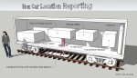
I want to input a level from 20 LDRs and output drive to 20 LEDs to make a train detector for my garden railway layout.
I idea being that an LDR will be between the tracks at points around the track and as the train passes over the resulting level change will be read by the picaxe and light a corresponding LED on a board the has a schematic of the layout so I can see at a glance the position of trains running.
I will also be planning to use a picaxe to show the setting of remote control points but that is another project.
I know that I have to use ADC as my input for the LDRs and In/Out for the LEDs the question is what is the meaning of for example D.7 {ADC27/touch} does that mean that the pin can be configured as an ADC input and what do I put into my program to configure it? I have read the readadc description in the manual but am not sure if I am reading it right.
 

Billo

Senior Member
You can't do what you want to do directly. The 40X2 has only 32 I/O pins. Can you get by with 16 LDRs and 16 LEDs?

Unless, of course you will drive the LEDs with a shift register.

But to answer your question, yes, if the pin description has ADC in it it can be configured as an ADC input.
 

GAP

Senior Member
thank you for that I might use 2 40X2s with some of the second one being for the points position display.
What do I have to put into the script to configure a pin to read ADC?
 

Billo

Senior Member
Just use the readadc or readadc10 (for 10 bit resolution).

e.g.

readadc 27, b0 - reads an 8-bit value on analog channel 27 (D.7) into variable b0

readadc10 27, w0 - reads a 10-bit value on analog channel 27 (D.7) into variable w0
 

AllyCat

Senior Member
Hi,
... what is the meaning of for example D.7 {ADC27/touch} does that mean that the pin can be configured as an ADC input and what do I put into my program to configure it?
Yes, the "ADC" part indicates that the pin has an internal connection to the ADC module. The number indicates the "Channel" number which "should" be used in the READADC or READADC10 command, not the Port.Pin number. In practice the compiler does "understand" the Port.Pin number, but NOT if it's represented by a Symbol (i.e. any Symbol declaration must use the Channel number). The "touch" indicates that the pin can be used as a touch-sensitive input and there are many other internal "Hardware" functions which are only available on certain pins, such as PWM Outputs, Data Buses, etc..

To drive motors or points etc., you generally do need a pin for each function, so you might need two pins for Forward and Reverse (or the equivalent). However, for indicating LEDs, there are various "tricks" (such as multiplexing) that can control (an average of) more than one LED per pin. One useful method (because it needs no additional hardware) is called "Charlieplexing" which can control a very large number of LEDs, provided that not too many are lit at the same time and/or they don't need to be too bright. 5 pins can just drive 20 LEDs, or 9 pins if they have 3-colours (Red/Green/Blue), i.e. 60 diodes for example. This can also reduce the number of wires required, but both the connecting arrangement and the PICaxe Program is somewhat more complex than a simple one-to-one connecting arrangement.

Cheers, Alan.
 

Buzby

Senior Member
Before exerting a lot of effort on a 20 LDR + 20 LED system, I would suggest you build a 1 + 1 and try it in different places around your track.

However, detecting light changes reliably when the equipment is outdoors is notoriously difficult, I would never try to roll my own solution.

There are many off-the-shelf devices on eBay and Amazon that would be perfect for this application, search for 'infra red barrier' or 'photo switch'. These devices are also already weather-proofed, another challenge you will face if you try to DIY.


Photoswitch photo.JPG.
 

AllyCat

Senior Member
Hi,

I totally agree that the OP should test one sensor before building 20 ! But I suspect that a sky-facing Retroreflective sensor might be even less reliable (and more difficult to hide in the track) than an ambient-light "shadow-detecting" sensor. In another thread the OP has proposed a differential LDR arrangement, with LDRs inside and beside the track.

However, I do agree about the pitfalls of using LDRs outdoors; presumably the days of encapsulated ORP12s are long gone. Most LDRs now seem very "cheap and nasty" and the very large (potential) resistance range means that insulation/sealing needs to be very good. I think I might be happier with Photo-Diodes which can at least be sealed and the wire connections protected with heat-shrink tubing, etc.. But of course they must be polarised correctly and the currents may be even lower than with LDRs.

Cheers, Alan.

PS: And Buzby knows all about Charlieplexing. ;)
 
Last edited:

GAP

Senior Member
This is the other detection method that I am considering, a bit more work but I am not sure of what inputs to the picaxe to use.
I didn't mention that the picaxe will be in a shed while the sensors could be across the yard over 10 Meters away so maybe LDRs may not work so this may force me to go down this track..
 

neiltechspec

Senior Member
Why not consider "Hall Effect" sensors, then it's just a simple task to glue small neodymium magnets to the underside of the locos.
No need to worry about light then. That's what I used on my indoor N guage layout.
 

Buzby

Senior Member
I was more thinking of a horizontal arrangement, with the train breaking the IR beam. The devices and reflectors could be hidden in trackside buildings. There are similar sensors to the one I posted, but with the beam at 90' to the body axis, great for hiding in trackside lamposts.

Regarding the dual LDR idea, detecting the difference between a mid-track shadow and trackside LDR, this might work, but it would need a lot of experimental work to get a reliable solution. LDRs have wildly variable resistances, even at the same illumination level, so each LDR pair would need characterising individually. Then you need to take into account the huge dynamic range of ambient light at different times of day and seasons, and they are temperature sensitive as well.

Much easier to use a ready-built IR solution. These do not use a continuous 'beam', it's modulated and synchronised between the TX and RX, so they can work in virtually any ambient light conditions. They provide a simple on/off signal, so no messing about with analogue calibration. They are already environmently protected, so no need to waterproof them. These would be my goto solution.

However, if I was determined to roll my own unique solution, I wouldn't be looking at beams of light or IR.

Passive IR detectors are simple and cheap. Mounting one mid-track would probably work. Because they use changes in position of IR illumination, not changes in brightness, they should be less susceptible to ambient light levels.

Another idea would be to try a so-called 'microwave radar' module. ( They are not really radar, they just detect radio wave disturbances.). These again are ridiculously cheap and simple to use. The bodywork of a garden train is probably big enough to trigger them, and no problems about ambient light.

Might be worth a try.

Cheers,

Buzby
 

AllyCat

Senior Member
Hi,
.... if I was determined to roll my own unique solution, I wouldn't be looking at beams of light or IR.
Agreed ! Since we are considering 20 sensors, my motto would be KISS (Keep It SimpleS). Trying to "hide" transmitter/receivers in trackside buildings, etc. just seems like too much (unnecessary) work and cost. Also there can be a lot of IR in daylight which might still "saturate" a (40 kHz) modulated receiver. I haven't read the linked article in #8 in detail, but at least the "Remote Control" type IR sensors are very sensitive, so could/should be located behind a very strong (attenuating) optical filter.

Personally, I would be inclined to avoid any form of "Active" sensor: certainly not transmitting light or IR, but maybe not even using Powered receivers. Although I suppose that a "bridge" (e.g. LDR potential divider) needs (common) Supply and Ground Rails; Or could you steal that from the Track nowadays? ;)

Much depends on the "size" and budget of the intended project and whether it needs to operate in very low light levels or at night, etc. (occasional direct sunlight is assumed, even for the UK). Thus, directly sky-facing Photodiodes (which are often actually transistors with no base connection) appeal to me, but I agree that Hall effect (if you can attach "button" magnets to all the rolling stock) or the passive "radar, people detectors" (used for automatic hand dryers and taps, etc.) are "interesting" for the application.

Cheers, Alan.
 

Flenser

Senior Member
neiltechspec's idea appeals to me because the hall effect sensors set along the middle of the rails could be easily installed so they are completely invisible
BUT
I've never used hall effect sensors so I don't know what you might have to do to use them over 10 meters to the shed.

Of course, you could use 2 PICAXE chips. One to monitor the sensors at the railway layout that comminicates using a serial connection to a second chip in the shed.

What ever types of sensor you choose to try out I agree with AlleyCat's advice to test with one sensor, to make sure you have a solution that works reliably, before building 20.
 

AllyCat

Senior Member
Hi,

The majority of Active Sensors will probably have a "TTL" type of output which should be fairly easy to transmit over 10 metres or more. You might even locate an 08M2 {LE} PICaxe at each sensor to transmit its data over a "one wire" data bus and greatly simplify the connections and the receiving end. Certainly LDRs may have a much higher impedance (perhaps 100k+ ohms) which could create problems with Crosstalk, etc., but you would probably put a capacitor across each ADC input that would swamp any crosstalk. These capacitors were one of the main discussion points in the other thread.

The magnetic approach does have a lot of appeal because modern magnets are easily available and can be very small and strong (they might even sometimes be too strong). However, there is one issue common with the IR approach; that the human eye cannot see IR or magnetism, so the designer may be working "blind". Hall sensors will be most sensitive in a particular direction (and maybe differently to N and S poles), the direction of the magnetic field from (particuarly the neodymium) magnets can be quite misleading (especially if close to an iron-based metal) and of course there's the Inverse Square Law, so spacing can be quite critical.

Cheers, Alan.
 

Buzby

Senior Member
Personally, I would be inclined to avoid any form of "Active" sensor: certainly not transmitting light or IR, ...
I'm completely of the opposite inclination !.

The through-beam or retroreflective devices are used extensively in industry, everything from counting cakes to opening doors automatically. They are simple to use, reliable, robust, and cheap. I've installed hundreds over the years.

Next on the industrial list is the inductive sensor. They are similar shaped to photo sensors, but are more limited in range. However, they are immune to getting optics clogged with oil or grease, and can come in very small packages. If the OPs train wheels are metal, then an inductive sensor may provide a solution.

There is still of course a real Old Skool solution that may be possible.

Each train wheel has a flange which runs on the inside of the rail. It might be possible to fit a simple roller or lever microswitch to trigger when the flange runs over it.

There is more than one way to skin a cat !.

Cheers,

Buzby
 

GAP

Senior Member
The microswitch idea was looked at but unfortunately the flange depth on my locos and rolling stock are not consistent (different manufacturers) so there is a chance that some carriages will not trigger the input and cause false readings hence an electronic method being considered.
I am leaning toward the IR beam across the track hidden in lineside structures and only putting them in areas where I cannot see the trains from the central control area eg behind trees thus reducing the number used but leaving open the option for expansion.
I did have delusions of granduer of trying to interface the picaxe to an old laptop and using a python program to drive a display but have shelved that and just going with a simple LED board.
As the line is going through a major reconfiguration all options are being explored.
 

radiosparks

Active member
Here's a thought for my 1% of inspiration::

Why not forget about running wires, all the remote sensors and associated signal problems.

Put the electronics in a Box Car! Using a Time-of-Flight sensor to measure the distance to a slotted card (aka. el-cheapo barcode scanner) wirelessly reporting back the last position. Each Car could have a unique code for identifying the train.

Power would come from the track and charge an internal battery. When the train is stopped the MPU could be put to sleep until the power has been turned on by moving the train. Or, just use plain dry cells and a power switch.

Using a downward mounted sensor, the distance measured, would be constant and easy to detect the changes. With 5 bit code you could have up to 32 locations reporting. The card would have a start bit and 2 stop bits, just like an ordinary serial signal (BAUDOT). You could have more bits, but the 08M2 might not be fast enough. The train will vary in speed, so the software will have to account for this, and if you run the train backwards this will not work. Each different Car per Train would need to be custom programmed for height above the sensor card. You only need 1 Car per Train.

Being outside, debris on the sensor card could effect the data returned. A track inspection would need to be done before running the Train.

Using a side mounted sensor you could have varying distances to the Car, that could work, by not having to add any reflective cards to the scenery, but actually measuring the distance to the scenery. You would need to run through the layout and create a table of various distances, then figure out where the train is located. Changes in scenery would effect the data, requiring a re-calibration.

This is only one half, the other half is the receiver and LED display. With a good antenna on the receiver you'll pick-up the signal from the yard.

I prefer a matrix driver MAX7219 to control 64 LEDs, but matrix wiring could be tricky.
OR, go with a port expander like an eight bit PCF8574. Three chips would control 24 LEDs, wiring would be more direct and easy to diagnose errors.

The only thing I don't know is your Train Scale. Anything below HO would be a tight fit (N,Z). Usually, (while dining) I sketch ideas on the back of a dirty serviette, so I drew a proper image.

Hope I haven't fallen overboard with this idea.
26211
 

Engle

Member
+1 for hall effect and inductive ideas and wow for the box car. Here's another idea that is going to make you wince but it has no moving parts or dirty optics or remote electronics. You could isolate sections of 1 rail with a small hacksaw or dremel cutter and feed each section in parallel to your controller (sorry). At the controller these sections fan out via a small resistor, perhaps 0.47 ohms, which is used to measure the current draw from the train. Both sides of the resistor are monitored by a "rail-to-rail" comparator :) If you're using DCC (AC signal) the output should be half wave rectified, which you feed to an RC circuit and tap off the capacitor for the digital input. If you're using traditional DC then you may need to parallel 2 comparators for forward and reverse currents on each section and then OR their outputs with diodes and a resistor and use that as a digital input.
 

kfjl

Member
Hi, GAP,

I think the best idea so far is yours : "delusions of grandeur".
Collect the information using Buzby's yoghurt-proof, squirting sausage meat-proof, door-opening sensors (I've seen them work), in a picaxe near your railway and send them by wifi, LoRa, NRF24, bluetooth, or whatever, to your laptop. A red circle for a led off, or a pink circle for a led on.
In Thonny or on a web page.
 

GAP

Senior Member
OK so many suggestions that my head is now spinning.
The idea of using Thonny (I had to google it to find out what it is) is appealing as I have an old laptop looking for work.
My python knowledge is next to none, with my picaxe knowledge slightly higher but not by much.

I must explain a bit about the railway it is what is known as "G or Large Scale" with the locos powered by onboard batteries and controlled by 2.4GHz radio control for speed and direction.
There is no power applied to the rails ie sometimes referred to ad "dead rail"

After thinking about what I would like to do I have come up with a plan that will use track location detection with signals on one part as it is what is referred to as "point to point" and not a continuous loop. There is a continuous loop part as well but I am treating them as separate layouts.
I am thinking of a train leave "top" yard after getting a go signal (via a push button on a control panel) and a signal at the bottom yard will show a stop signal.
Two sensors at the exit to the top yard will be used to show train direction at the halfway point a detector will return the go signal to stop and nothing will be allowed to move on the line till the train passes sensors at the bottom.
This is the first step the second will expand to allow 2 trains on the line running in the same direction but separated by half the track length.
The system will be set up so that a train starting at the bottom will do the same but in a reverse direction.
I am going to write out my logic in plain English and refine it before trying to write some code so I will most likely start a new thread when I do.

Just to finish off could I use some small picaxe's to do the detection and signal control work (slaves) and then feed outputs to a master picaxe that could do the display/ or possible pc interface work? This may be another thread as well.
 

PhilHornby

Senior Member
My python knowledge is next to none, with my picaxe knowledge slightly higher but not by much.
I recently used ChatGPT to write a BLE interface in Python, for one of these: Battery Monitors.

It's over ten years since I last dabbled with Python, but found that ChatGPT spat out (working) Python code faster than you could blink.

I started with some code I'd found, that didn't work ... and just asked "can you get rid of all these error messages"? ;) ... which it did ❗
A few more iterations, where I told it about functionality that I wanted and I had working code that is far, far better than the Android app. that was supplied with the device!
 

Buzby

Senior Member
Collect the information using Buzby's yoghurt-proof, squirting sausage meat-proof, door-opening sensors (I've seen them work),
Do you work in industrial control, like I did ?. I have worked with dairy machines and sausage machines, as well as door openers !
.... send them by wifi, LoRa, NRF24, bluetooth, or whatever, to your laptop.
I think in this case the OP should just use wires. There is too much work involved in designing and building wireless devices. He wants to control trains, not spend a lot of time learning about protocols and aerials.

Use off-the-shelf retroreflective IR sensors, bring the twenty signals back to a 40X2, write some simple code to send via serial to a laptop or RPi, use Thonny or similar to build the display.

In fact, if it was my project, I'd not use PICAXE !.

Something like M31-AXXXA000G sixteen input RS485/Ethernet ModBUS to collect the signals, then an RPi or laptop to display. There are plenty ModBUS implementations for Python. In future, more ModBUS modules could be added to drive lights and points on the track.

This means the construction is just wiring, no need to build or program the interfaces. The only code needed is in Python, and Thonny makes that an easy learning curve.

Off-the-shelf solutions will always be more robust than a home-brew, unless the OP wants to spend time tinkering with circuits instead of driving trains !
 

AllyCat

Senior Member
Hi,
the locos powered by onboard batteries and controlled by 2.4GHz radio control for speed and direction. .... There is no power applied to the rails ie sometimes referred to ad "dead rail"

..... could I use some small picaxe's to do the detection and signal control work (slaves) and then feed outputs to a master picaxe that could do the display/ or possible pc interface work?
Ah, quite an "unusual" application which may affect the options quite significantly. Thus the "boxcar" proposal in #19 might be more relevant, but doesn't need a "Time of Flight" sensor; a simple active IR detector should be sufficient**, or going to the other extreme, it could use a GPS receiver with a completely unmodified track. ;) Stop Press: But I agree with Buzby that simple (beside-track) wiring is probably the best approach.

However, my first questions would include the "nature" of the track. Can (or could) it provide an electrical "Earth" connection back to the "Master" PICaxe or PC, i.e. are the running rails connected to each other (laterally and/or serially)? Yes, you could use localised "Slave" PICaxes (I suggested that back in #14) but they do need to get power from somewhere! That could be achieved with a (customised) "One Wire" Bus (i.e. carrying both power and data) but that still needs an "Earth Return"; or the data could use a Radio return path (433 MHz is probably the easiest). Alternatively, if the rails are NOT connected to each other, then it might be possible to use the method that I believe is used by some "real" railways, i.e. detecting the "short circuit" between the running rails produced by the wheels and axles of the rolling stock.

** Going slightly Off-Topic: The Australian-Designed "Edison Robot" runs over customised Barcodes to Program (or more strictly Configure) itself. The Robot might be considered to be a "Competitor" to PICaxe, but their individual Strengths and Weaknesses are actually quite complementary (Hardware and Software). In principle, Edison and PICaxe can communicate with each other (via IR), but it's not as easy as it could (or should) be. However, I believe that I have "solved" most of the issues and hope/plan to start a related thread at some time in the future.

Cheers, Alan.
 

kfjl

Member
Do you work in industrial control, like I did ?
Three or four decades ago I worked as a pipe-fitter/welder/sheet-metal worker, a lot of the time in industrial food factories. That's where I saw the sensors. At the time, all I needed to know about sensors was to keep the welder's ground-clamp as near as possible to what I was welding so I didn't melt the sensor's wires (sorry if I melted some of yours! :)).

I'd wire up all the sensors to the railway-side picaxe in order to collect all the information in one go and avoid any potential radio "data collisions", and then send it (interrupt on a change) to another picaxe connected to a computer. "Virtual" leds will save 20 output pins.

Whatever you choose, I'd work from the end back to the beginning, ie:
- choose your visual interface
- get the communication between the railway picaxe and the computer working
- get your sensor-information collect working.

The choice of link between the railway-side picaxe and the computer would depend on the distance between the two.

If I were more interested in trains than electronics, I'd buy something off-the-shelf that does what I want, without the hassle of learning stuff that I'd probably never use again.

If I were friends with google, (spit on the ground) I'd start by trying to get ChatGPT (spit on the ground) to write me an android (spit on the ground) app as suggested by PhilHornby.

A link or two:

https://picaxeforum.co.uk/threads/picaxe-port-serie-et-python.22425/

for sniffing communications in python between a picaxe and a computer.

Picaxe blogs archive with a K in a brown circle (for sending one byte from any "something" with a serial port to any other "something" with a serial port).

But PhilHornby's idea seems to me to be the best (easiest) bet for rolling your own solution.
 

GAP

Senior Member
Thanks for the link to the french forum I translated it and I might have a play with it.
I couldn't find the Picaxe blogs archive so I will have to do more searching for it.
 

PhilHornby

Senior Member
If I were friends with google, (spit on the ground) I'd start by trying to get ChatGPT (spit on the ground) to write me an android (spit on the ground) app as suggested by PhilHornby.
It was actually a Python script, but hey, I bet it can do Android apps too :unsure:
 

kfjl

Member
It was actually a Python script, but hey, I bet it can do Android apps too :unsure:
My bad. I'll mop up. :)

The blogs archive is just above the sandbox, but I wouldn't bother with the wireless stuff. I'd forgotten you're only 10 meters or so from the circuit. Try a cable as Buzby suggested.
 
Top