29 12V outputs, 256 timed events: 20M2, MCP23017, ULN2803

lbenson

Senior Member
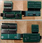
Hedingham's dollhouse lighting thread made me wonder about a convenient way to turn on and off lots of 12V lights on a 24-hour timed schedule. I've designed PCBs, had them manufactured, and and have tested a 20M2 design which, with an MCP23017 I2C I/O extender allows control of 29 lights, with 256 possible turn-on times with a possible duration of 4 hours, 15 minutes each.
23347
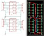
Eagle File Schematic and PCB Images:
23348

23349

23350
 
Attached file: 20Lights2_eagle.zip -- Eagle Cad sch and pcb files for possible modification

Attached gerber files: 20Lights2.zip, uln2803_MCP2317v2_2019-12-02.zip, uln2803_2019-11-20.zip

The gerber files can be uploaded directly to JLCPCB.COM for manufacture. Five each of the 20M2, ULN2803, and uln2803_MCP2317 PCBs costs about $16 U.S. with slow boat shipping. With 10 of the ULN2803s (since each 20M2 can take two of them), it's about $17. Express delivery was about $10 more and took 7 days to get to me.

Two of these would allow control of up to 58 lights, with one pin on each (C.6) available as an input. (Other portB or portC pins could be used for other purposes, reducing the number of outputs.)

I tested with these 12V LEDs (10mm versions).
 

Attachments

Last edited:
Code for slots 0 and 1 attached.

The code is based on a table in each slot consisting of up to 128 4-byte entries (each slot) giving hour, minute, duration in minutes, and pin#, like this:
Code:
' hour, minute, time-on in minutes, pin
table 0,(0,0,25,6)
table 4,(0,8,2,16)
table 8,(0,8,9,2)
table 12,(0,18,6,17)
. . .
table 496,(11,38,6,25)
table 500,(11,49,16,11)
table 504,(11,59,30,31)
table 508,(12,8,12,26)
The first entry means that at midnight (0 hours, 0 minutes, pin 6 will turn on for 25 minutes. The final entry means that at 1208 (military time), pin 26 will go on for 12 minutes.

The pins are numbered as follows: 0-7 is B.0 to B.7; 8-15 is C.0-C.7; 16-23 is MCP23017 portA 0-7; 24-31 is MCP23017 portB 0-7. Pins B.5 and B.7 are reserved as the I2C pins. Pin C.6 is input-only, so also reserved. In this case I used pinC.6 as a switch for running using the attached DS3231 real-time clock when pinC.6 is high, and a one-minute-per cycle time when pinC.6 is low. I used a weak pullup command on pinC.6 (PULLUP $4000) to make the program normally use the RTC. When pinC.6 (bent up) is jumpered to 0V (as show below) the program runs in hardware simulation mode of one minute per cycle. It takes about 8 minutes to run through 24 hours, at which point the program starts over.
23361
I used this RTC module and this MCP23017 module.

If you start with pinC.6 in RTC mode (not jumpered), the program will quickly scan through the table entries less than the current time, and then continue in real time. If you then jumper pinC.6 to 0V, it will go to fast mode from that time.

The easiest way to build the table for many pins over 24 hours would be to build an ordered list in a spreadsheet, and write a VBA program to output the table. I generated the table I used with random times, durations, and pins.

The program turns everything off 61 seconds after 11:59pm, so everything starts afresh when the switch is made back to slot 0.

This has been tested for multiple days worth of simulated time, but only for short periods of real time.

(Note: when the ULN2803 is connected to portC, it appears to act as a pulldown for pinC.6, so that pin must be bent up to prevent the program's always running in simulation mode (the pulldown overcomes the program's weak PULLUP).)

(Testing revealed glitchs in switching between slots in real time, so I've modified both programs and uploaded them anew. Should anyone use these, they should download just before trying in case there are further changes.)
 

Attachments

Last edited:
With 5V leds, I ran this Christmas tree of a rig for 3 days using the DS3231 Real Time Clock.
23435

Then, because I could (since there's an I2C connection for a second MCP23017 on the PCB), I made a 45-light version. It's run for over 2 days. Here it is with 5V LEDs:
23436

The MCP23017 on the right has had the 0-Ohm resistor for A0 moved from 0V to VCC, so its address is %01000010.

(Both MCP23017s have pullup resistors on SCL and SDA--depending on what else is attached, they might need to be popped off of one of them.)
 

Attachments

Back
Top