marzan
Senior Member
Hi everyone. I am starting a new project. I want to build a controller for my rainwater tank. I`ll explain:
Rainwater is hooked up to the toilet and the irrigation system.
Pressure pump is 12 v 20lpm running from Lead acid batteries recharged by solar panels.
I want the controller to:
Limit the pump to run for a maximum of 5 minutes before shutting off the pump UNLESS it is in a specified time period set to coincide with the irrigation system.
check the water level in the tank via a pressure sensor in the outflow pipe at the bottom of the tank.
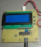
Lcd display to show how much water is left in the tank as well as menus to set time of an rtc chip, set time for automatic override for the irrigation system, daylight saving forward/back menu item, and manual override menu item.
Dorji 433 MHz modules to also receive info onto a remote lcd screen (or in a perfect world an app on my computer)and a piezo to operate when tank low or time exceeded.
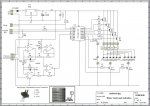
I have come up with the following circuit diagram. Sorry if it isn`t very neat:
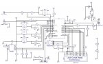
can anyone suggest any improvements to the circuit?
I thought this might be a good way to learn some new things.")
Marz.
Rainwater is hooked up to the toilet and the irrigation system.
Pressure pump is 12 v 20lpm running from Lead acid batteries recharged by solar panels.
I want the controller to:
Limit the pump to run for a maximum of 5 minutes before shutting off the pump UNLESS it is in a specified time period set to coincide with the irrigation system.
check the water level in the tank via a pressure sensor in the outflow pipe at the bottom of the tank.
Lcd display to show how much water is left in the tank as well as menus to set time of an rtc chip, set time for automatic override for the irrigation system, daylight saving forward/back menu item, and manual override menu item.
Dorji 433 MHz modules to also receive info onto a remote lcd screen (or in a perfect world an app on my computer)and a piezo to operate when tank low or time exceeded.
I have come up with the following circuit diagram. Sorry if it isn`t very neat:
can anyone suggest any improvements to the circuit?
I thought this might be a good way to learn some new things.
Marz.