Your opinion counts - questions regarding simple but usable oscilloscope

What features do you think woulb b be important for my proposed low-end oscilloscope?

  • I would like to have an enclosure and custom end panels (as opposed to bare board only) - adds ~$5

    Votes: 30 69.8%
  • I want BNC connectors for the probes - adds ~$3 compared to jumper headers

    Votes: 25 58.1%
  • logic analyzer functionality is very important

    Votes: 29 67.4%
  • I want to be able to use 1:10 scope probes with the instrument (standard is 1:1 grabber probes)

    Votes: 23 53.5%
  • The scope should be able to provide fuse-protected ~5V/300mA USB power to my circuit

    Votes: 14 32.6%

  • Total voters
    43
  • Poll closed .

womai

Senior Member
Right now I am leaning towards offering two versions:

(1) minimum-cost bare-board version with RCA connectors included - you'll need to build your own probe for that.

(2) with enclosure, BNC connectors and a pair of BNC-to-micrograbber probes included - sounds like that is what you would like to get.

Both will be self assembly kits, so even for (1) you could still chose to install BNCs instead of the RCA connectors.
 

womai

Senior Member
Here's another 3D rendering of the board. Realized I can scale the models so e.g. the resonator has a more realistic size. Still missing the BNC connectors and the USB jack. Thanks to svejk for the header models!
 

Attachments

Svejk

Senior Member
My next 3 days will be really busy, but I can make those missing components Friday afternoon or Saturday if you'll give me a link to them. I know now how to color them properly but I need some time.
 

womai

Senior Member
Hi Svejk,

thanks for the offer - I am going to take you up on it. I searched the web wide and far, but all I could find (for free) was a not-so-great 3ds model of a non-matching BNC connector and a couple USB models that make Diptrace crash when I try to load them...

Here are the requested links:

BNC connector (it's a standard footprint so you can find many others that would work as well):
http://www.mouser.com/ProductDetail/Molex/73137-5003/?qs=ldwB34exYZUMRxRXTNcLMQ==

USB connector (again, pretty generic footprint - it's a through-hole USB type B jack):
http://search.digikey.com/scripts/DkSearch/dksus.dll?lang=en&site=US&WT.z_homepage_link=hp_go_button&KeyWords=AE9925-ND&x=0&y=0

Thanks in advance!

Wolfgang
 

Flenser

Senior Member
Womai,

If the fuse protection is a polyfuse in the 5V trace upstream of the logic analyzer header then wouldn't it implicitly be an optional feature?

If the PCB included the holes for the polyfuse then those who don't want fuse protected supply to the circuit either replace the polyfuse with a link (for an unprotected 5V supply) or don't install anything (for the logic analyzer function without the 5V supply).
 

womai

Senior Member
I may still add a place for the fuse as suggested. The only thing I dislike about is that the 5V supply is the least wanted feature in the poll (only ~30% of the respondents think it is important), so I am a bit reluctant to add something that adds work and/or cost for everybody when it is needed only by a minority.
 

John West

Senior Member
Add the pads for the Polyfuse and treat it as a circuit device, (no solder masking on the pads) but put a connecting trace between them. That way, only those who wish to add a Polyfuse will need to do anything; cut the trace and add the fuse.
 

BillyGreen1973

Senior Member
Womai,

This may be a daft question, so feel free to laugh openly..

will the .hex files for the PIC micro be made freely available, along with schematics and PC software?

Just wondering, since it would be well within the realms of a lot of people to program their own PICmicro and produce their own PCB.
 

John West

Senior Member
A good idea is being turned into a useful and open device at a dirt-cheap price.

I don't know how it's said in other countries, but in the US these days, we'd say, "Wolfgang's the man." :)
 

womai

Senior Member
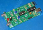
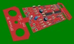
Ok, I put a placeholder for the fuse in like John suggested. I used a 1206 SMT footprint - that is easy to solder even for a beginner. I was not able to find reasonable fast polyfuses in a through-hole package, while 1206 packaged ones offer down to 100 msec. If you don't care about the fuse protection there is no need to do anything. If you do, you need to cut the trace between the two SMD pads and bridge it with the polyfuse.

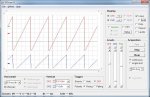
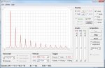
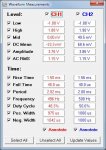
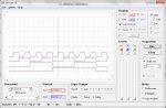
I also ran some quick code simulations, looks like the logic analyzer can achieve at least 500 kSamples/sec for a record length of >800 samples. That's just about sufficient to debug standard 100 kHz I2C or 115 kbaud RS-232, which is good news. At least initially triggering will be very simplistic - rising or falling edge on one selectable channel out of the four (that allows to use the "interrupt on change" feature which will guarantee very fast reaction times).

As far as source code is concerned: The PC software will have the executable freely available, but probably not the source code. This is because it shares most of its code with the original DPScope which has become a commercial product.

For the firmware I am still planning to make the HEX file available. The printed circuit board has a place for an ISP header so you can program the chip in place using a Pickit 2 or 3 programmer. That said, I suspect that only few people interested in this scope will have a suitable PIC programmer at their disposal (the Rev-Ed programmer BAS800 does not support this chip). So I will also offer the scope as a self-assembly kit with PCB and pre-programmed microcontroller. I'll keep the markup small, and since I can buy in bulk chances are it will be cheaper than anybody could get the parts for a one-off (especially considering shipping expenses for the components, and the work and expense of a self-made PCB). I'll be happy if that at least ends up covering the development expenses (only counting the $$, not my time - after all, this is fun!).
 
Last edited:

papaof2

Senior Member
I'll be happy if that at least ends up covering the development expenses (only counting the $$, not my time - after all, this is fun!).
I'm glad you find this fun, as it makes the 'portable lab' I want affordable ;-)

John
 

womai

Senior Member
Ok, I took the plunge and ordered a set of PCBs for the prototype. Found a place that will to 10 boards for an incredible price (no setup fee - that makes all the difference) and still accepts standard Gerber files - only hitch being that the size is limited to 10x10cm, no cutouts or large holes, so I had to omit the end panels. But will be good enough to test the circuit, develop the firmware, and build up a couple bare-board versions. Keeping my fingers crossed that vendor works out.

Also need to order components now...
 

womai

Senior Member
Yeah, that's the one. I'll eventually move the fab to PCBCart like for my other projects where I need more than a dozen copies, but I figured for $33 for 10 boards including shipping I'll just give it a try - if it works out then this is better than wasting time breadboarding the whole scope (which wouldn't even tell me if my layout is correct). PCBCart's setup fee is too high for such a quick and dirty try, but in the end I like their gold finish (classier than HASL solder finish) and the full board exceeds 10x10cm anyway.

I already saw on eevblog that itead has some issue with fine-pitch structures, but my board has nothing finer than about 12mil, i.e. twice their 6 mil minimum.
 

Andrew Cowan

Senior Member
[slightly OT]Andrew - How long do they take to arrive?
I've only used them once so far, but it was about 16 days - fantastic for PCB production. However, the order probably arrived just as a panel was being finalised (or something) - I'd be suprised if it was usually this fast.

A
 

womai

Senior Member
Well. I'm still waiting for the boards. Postal tracking shows the boards have been sent, but does not give any more details.
 

womai

Senior Member
Received the boards today - looking pretty good, manufacturing quality very decent for the price. Also have acquired all the other components, so I should have the first prototype put together in a day or two. Then it's time to work on firmware & PC software...

Wolfgang
 

womai

Senior Member
I've successfully put the first prototype together. Attached are two pictures. One shows the bare board version with audio (RCA) connectors; the second shows the board with BNC connectors mounted in the enclosure. The connector footprint ia a merge of BNC & RCA footprint so the you can install either one on the same version of the board. In addition there are 0.1" jumper headers if one wants to hook it up to a breadboard with standard jumper cables.

I had to steal a front panel from my "classic" DPScope, and there is no back panel yet (the maximum board size at iTead is 10x10cm so did not allow to include the end panels), but it already gives a good impression how the instrument will look like. The final PCB will be red like the end panels, and have gold plating instead of reflowed solder.

Next thing is to get the PicKit to talk to the microcontroller and start developing the firmware. Blinking an LED will be first ;)

Wolfgang
 

Attachments

womai

Senior Member
...and the LED is already blinking!

One nice feature is that I can program the PIC in-circuit since the board has the ISP connector designed in.

Just back from a strenuous 3+ hour bike ride to the beach and back (not what you think - there are mountains inbetween an we crossed them twice!) so a huge portion of chocolate sounds very tempting to me! :)
 

womai

Senior Member
Small status report:

USB link between scope and PC is up and running. Real-time sampling up to maximum rate supported by internal ADC (20 KSa/sec on two channels) is up and running. Frame rate is well above 20 frames/sec. Measured analog bandwidth is approx. 250 kHz which fits fine with the planned 2-4 MSa/sec maximum equivalent time sample rate.

Next on the list is triggering and then equivalent time sampling.

Wolfgang
 

womai

Senior Member
Actually equivalent time sampling is easier to achieve than real time sampling; get the trigger, wait for some time T, acquire one sample; get another trigger, wait a little longer (T+dt), acquire another sample; and so on until the buffer is full. The wait time increment dT can be much smaller than the fastest real-time sample rate so you can look at much faster changing signals (provided they are repetitive with regards to the trigger).
 

womai

Senior Member
Progress update:

Triggering on CH1 is working, with selectable polarity (rising and falling), and adjustable threshold. I'm thinking of allowing an external trigger - one possible input pin to the comparator is unused so I could feed it out on the backpanel connector (together with the logic analyzer pins); no added cost, and it would increase the trigger option selection to Auto, CH1, External.

Equivalent time sampling is working up to 2 MSamples/sec equivalent rate (5 usec/div display scale), and it successfully copes with signals up to almost 100 kHz frequency; there are some issues with timing stability; I suspect it is because sometimes the next trigger interrupt comes in just when the program is still returning from the previous sampling interrupt. This causes about 3 usec of timing jitter, quite visible at the highest resoltion settings. Tried about a hundred different things to get rid of that but no luck so far; but putting in a randomized holdoff timing at least smears out the effect so one can remove it by averaging for a clean-looking signal.

The PC software side is still a hack - most settings are hardcoded and need to be changed by changing the code; next step is to clean this up so the parameters can again be set from the GUI with sliders, comboboxes and pusbuttons.

Overall, looking good and the scope part of the instrument may be finished soon.

Wolfgang
 

womai

Senior Member
Some good progress over the last few days. The scope GUI is close to finished. Automated measurements and FFT (frequency domain display / spectrum) are working as well. Now I have to clean up the datalogger mode, then I'll move over to the logic analyzer functionality.

Attached are a few screenshots to whet everybody's appetite.
 

Attachments

John West

Senior Member
I'm absolutely psyched, Wolfgang. The screens look great. The data analysis is impressive. It looks like you're nearly there with this project.

A suggestion:
I don't know what your o'scope "Utilities" functions include, but a very handy one would be a large "live" frequency counter display of one analog channel frequency or both (square wave mode too, as that's often hard to read with typical freq counters) for folks who are playing with freq measurements. I really dislike trying to read small numerical displays while I'm tweaking things, so that would be a sweet addition to this system.
 
Last edited:

womai

Senior Member
John,

thanks for the praise! I'll note the suggestion with the frequency counter. May be a while before I get to that though There's still quite bit more work - right now I am playing around with different concepts for the logic analyzer (quite fast but no pre-trigger and only simple triggering? Or slower but with complex triggering? Or both options? Or...?). And I'll be traveling for a few weeks, leaving in a few days. The good thing is that so far I could leverage large parts of the DPScope software - e.g. the measurements required only a few new lines of code to make them usable. That won't be true for the logic analyzer mode.

Other additions I am considering are

- external trigger input (CMOS levels)
- square wave / clock output (unfortunately PWM is already used for the trigger threshold)

Wolfgang
 

John West

Senior Member
Perhaps you might make any interesting and useful firmware mods now, then start shipping this test tool without the additional necessary PC code in place for new features. Then at your convenience develop the PC code for the additional features. It appears to me that you already have a very useful little device up and running, and it would be great to see it out and in use asap.

If feature upgrades are all on the PC side, you can simply post the upgrades as they become available. That would get the device out to the user more quickly, and provide them with a piece of gear that just keeps getting better and better.

It's well understood that the heavy work is in the software interpretation of incoming signals, not so much in snagging them to begin with, which it appears you have well in hand now.

Even if firmware changes to the PIC became necessary later on, I'll be putting both chips in sockets (machined-pin) anyway, and I'd be happy to purchase firmware upgraded chips for my scope, as I'm sure many others would. So you could easily start shipping out this multi-purpose PICAXE test tool much sooner.

Better to wait for the features than to wait for the scope. ;)
 
Last edited:

womai

Senior Member
I'll definitely put in some hooks for future extensions, including the ability to read and write arbitrary RAM and EEPROM addresses. Equivalent time sampling could be improved in terms of speed, and some offset/gain calibration is another feature plan on - both will only need changes to the PC software.

But there are limits to what you can do this way. The datalogger will need highly optimized code for triggering and data acquisition, so this needs to be in right away. I also need to do much more real-life testing - I typically pride myself that what I ship has little or no bugs right away; especially worthwhile if a critical firmware fix means mailing out dozens or hundreds of chips...
 

womai

Senior Member
Good news - finally got back to this development and made great progress over the last few days. Cleaned up a few minor bugs and then implemented the 4-channel logic analyzer. Acquires at up to 500 kSa/sec real time (good enough for 100 kHz I2C, 112 kbaud RS-232 and so on), record length 860 samples, trigger on any of the 4 channels. The inputs are TTL compatible so they should work with TTL signals as well as with 5V, 3.3V and with some luck 2.5V CMOS logic (have no way of really testing this right now since I am not staying at home over the holidays). 800 kSa/sec is in the works (cuts the record length in half).

Below is a screenshot showing the logic analyzer in action - input is a 4-bit binary counter signal generated by a Picaxe 18M2.

If all goes well the kits will be available in January, once the firmware is complete (I can always clean up and improve the PC software, but a firmware change would be a major PITA once the hardware has left my home...).

Wolfgang

DPScope SE - logic analyzer.jpg
 

womai

Senior Member
Yes, here is my Swiss bank account number...

no, just kidding. First I want to finish the hardware and firmware and put together a number of kits, then I'll put it online - I don't want to take anybody's money when I am not yet ready to ship. Second I need to do a test build of one of the kits to be sure I everything works flawlessly and make sure I did not forget any components, and take pictures of the assembly for the yet-to-be-created assembly manual. Lastly I need to run the numbers to figure out what I need to charge to cover my cost and also the least costly method for international shipping from Germany. I really intend this to be a Picaxe tool anybody can afford, even a starved student :) A while ago John West generously supplied a box of suitable components (sockets, resistors etc.) for free just out of enthusiasm for this project, so for Picaxe forum members I want to pass this on in the form of further price reduction for the first batch of kits for forum members only. I already ordered and received the printed circuit boards past summer so I am ready to go with very short lead time. Can't tell you how much fun it is to see something coming together in reality that I had in my head for quite a while now!
 
Top