Your opinion counts - questions regarding simple but usable oscilloscope

What features do you think woulb b be important for my proposed low-end oscilloscope?

  • I would like to have an enclosure and custom end panels (as opposed to bare board only) - adds ~$5

    Votes: 30 69.8%
  • I want BNC connectors for the probes - adds ~$3 compared to jumper headers

    Votes: 25 58.1%
  • logic analyzer functionality is very important

    Votes: 29 67.4%
  • I want to be able to use 1:10 scope probes with the instrument (standard is 1:1 grabber probes)

    Votes: 23 53.5%
  • The scope should be able to provide fuse-protected ~5V/300mA USB power to my circuit

    Votes: 14 32.6%

  • Total voters
    43
  • Poll closed .

womai

Senior Member
All,

made some good progress on this effort. In fact, I have the thing running in datalogger mode (without any analog frontend of course, just a trimmer feeding the ADCs). Now the question is - what would people prefer - see attached poll.

For anybody not familiar with the topic, the original (long!) thread is here:
http://www.picaxeforum.co.uk/showthread.php?t=15814

Basically I am trying to decide if I should create the simplest, rock-bottom lowest-cost-possible instrument, or add some bells and whistles (and make it look much more professional).

The enclosure would make it look very similar to my DPScope (http://www.dpscope.com). It would also protect the circuit (and potentially allow use of higher voltages with a 1:10 probe without posing a hazard to the user). With an enclosure BNC connectors would be mandatory.

Thanks for taking the time to answer!

Wolfgang
 
Last edited:

John West

Senior Member
I'm of two minds about this, womai. I'd like to see it available as a dirt cheap "bd and IC's" minimal feature version for those with very little money who are willing to box it up and add what connectors they have and features they need, and also as a complete kit with all the nice bells and whistles ready to install.

I think there is a market for both versions. If there is only the option of one version, I'd have to opt for the stripped down version in keeping with the original idea of a reasonably functional but very inexpensive unit.
 

inglewoodpete

Senior Member
For me, a low-end oscilloscope should be low end. Standard 0.1" polarised headers for the probes (Eg Molex or equivalent). I can't see the benefit of using BNC fittings and relatively expensive probes. I'd be connecting the molex pins to RCA connectors anyway and using simple shielded audio leads with croc clips or mini "beak" probes.

A fuse would not be a priority for me. USB feeds' spec is for overload protection. And if a chip in the oscilloscope pops, replace it!
 

premelec

Senior Member
Hi, the logic analyzer would be good - 5v power can be obtained from another USB plug and BNC connectors don't seem required for these low frequencies. Perhaps RCA jacks would do and anyone wanting BNC could use an adapter... bare board with optional case probably best.

I'm not sure what your maximum input V will be without 10:1 but I'd like to go up to 36v input without anything emitting smoke. You don't mention DC vs AC coupling availability but an instruction sheet on input variations could be supplied rather than making all the options easily switched in or out. It _would_ be good to have some known input resistance and capacitance with fairly close tolerance so compensated HV probes could be made without much trouble. If this happened to be what 'standard' probes need that would be good... :) Thanks for your efforts!
 

womai

Senior Member
Well, thanks to all who reponded so far (10 people total). Please keep the votes coming - don't complain later that the thing does not look the way you wanted it to! So far seems like most people want the logic analyzer (darn - was hoping to get out of that because that will be a lot of work :), and a fully boxed version is attractive to about half.

Adding jumper headers in parallel to the BNC connectors is trivial, I will do that then. So people can choose between a bare-board version with these headers vs. a boxed version with BNC.

I am loath to do two versions of the PCB, so having the boxed version available means a larger board and higher board cost (about $1 - $1.50) - so it fits the DPScope enclosure and has the end panels as part of the PCB. That way I can at least keep the cost of the enclosure (and the BNCs) way down since I piggy-back onto DPScope volume orders.

@Premelec: Max. voltage range will be +/-20V (actually +/-25V for 5V nominal supply, so I have some headroom if the USB port supplies less; the scope will automatically measure and correct for lower voltages but it will reduce the total range). There won't be any smoke if you exceed that (the design should be safe up to at least +/-100V or even +/-200V - but you won't see anything useful on the screen).

I'll strive for standard 1 Mohm input impedance (and standard ~15-20pF capacitance) so you can extend the range with standard 1:10 scope probes. Unlike the DPScope there won't be any adjustable compensation for 1:1 input (capacitive trimmers would add too much cost), but in 1:10 setting you can use the probe's adjustment instead.

No AC coupling provided, but adding a capacitor and a miniature SPDT switch will do the trick if you want to mod it yourself.

Wolfgang
 

womai

Senior Member
One more update, I did a few tests with the ADC today. I'll have to run it somewhat outside spec, but even then 20 kSa/sec on two channels is about the best I can do (I was originally hoping to push it to 50 kSs/sec but it didn't work with the available settings). That said, for repetitive signals I can always do equivalent time sampling (putting the waveform together from several acquisitions), that will at least go to ~2 MSa/sec equivalent rate, to make full use of the ADCs analog bandwidth - good enough to look at signals up to ~200 kHz. Will be transparent to the user (and similar in functionality to any analog scope which needs repetitive signals as well to provide a steady picture).

The logic analyzer should be able to do quite a bit higher rates single-shot since it does not use the ADC.
 

inglewoodpete

Senior Member
So far seems like most people want the logic analyzer (darn - was hoping to get out of that because that will be a lot of work .....
Wolfgang
I'm presuming that the logic analyser is "just" a software/firmware update that can be added later?

At a minimum, AC coupling can be done with a capacitor and an SPST switch to bypass it for DC, unless you need to include compensation.
 

BillyGreen1973

Senior Member
I think most posts on this seem to agree, but I think a basic scope aimed at the novice, should be just fine.
To be honest all I would need from a small scope, is to look at serial comms, I2C, and PWM for rc servos etc.

Looking forward to placing my order :)
 
Last edited:

techElder

Well-known member
It would be SO much better if your PCB had the connection points for all of these "options" that you mention. Not necessarily room for the components, but at least a way to make connections without drilling little holes.

... Adding jumper headers in parallel to the BNC connectors is trivial, I will do that then. So people can choose between a bare-board version with these headers vs. a boxed version with BNC.

... I'll strive for standard 1 Mohm input impedance (and standard ~15-20pF capacitance) so you can extend the range with standard 1:10 scope probes. Unlike the DPScope there won't be any adjustable compensation for 1:1 input (capacitive trimmers would add too much cost), but in 1:10 setting you can use the probe's adjustment instead.

No AC coupling provided, but adding a capacitor and a miniature SPDT switch will do the trick if you want to mod it yourself....
 

hippy

Technical Support
Staff member
I would agree with Texasclodhopper. What I think the ideal situation would be is a PCB which can support the full spec scope but designed so people can start with the bare minimum, with documentation on what wire links to add to make that work.

I suppose the question is, what's the bare minimum ? To me that would be a single chip PICmicro, minimal circuit, just flying leads to measure voltages straight into the PICmicro. It could be built on strip-board for real penny-pinchers.

Of course that's mere 'toy' to some and to make it more credible it needs ADC buffering, then needs to handle 10:1 probes via BNC with offset adjust and AC/DC selection to be credible with others.

I'm not sure the poll will be all that useful to you as it probably only highlights the 'likes' of a need, want, likes criteria. I may need a dirt-simple, cheapest scope, but I want more than that, and I'd like a $2K scope for $2 :)

While providing USB power to a target board is nice it's not essential and could be termed 'feature creep'. Though perhaps no reason not to add it if it's a zero-cost option to the end-user. I could say it needed selectable current limiting to be usable, and that's even more feature creep. In reality, I doubt anyone would really care whether it was there or not. You could perhaps approach it the other way round; "would lack of this make you not buy it", "make it unusable".

I don't want to appear critical because I'm not, I support the idea. I just think you may need to be cautious that you don't turn "simple" ( that is, low-cost ) into something too complicated for sake of the "usability" demands of those who want more. It's always tempting to give more, but there's the danger of turning the humble two-slice toaster into the Goblin Teasmaid with George Foreman Grill and Expresso machine, turning a Notepad editor into Microsoft Word. In the process you can lose the essence of what you initially aimed for, gain interest from a new market share but lose the market you initially targeted.
 

hippy

Technical Support
Staff member
An interesting thing about the poll; after 21 votes some 75% say Logic Analyser is important to them. Though there are some which combine both functions I've never considered them other than as separate tools, and same too for waveform generation ( which I've never had any need for ).

The unanswered question is; are people voting for LA functionality because that's what they really want and have little interest in the scope side of things ?

Is it better to design a low-cost scope, a low-cost LA, a low-cost AWG as separate tools rather than combine all together, put aside that it could all be done with the one chip, the same board ?

Again it may be a case of turning the question around, from "would you like this" to "if it doesn't have that, is it acceptable" ?
 

John West

Senior Member
I'm led back to the thoughts of my original suggestion, a bd with the layout done to provide capability for all three functions fairly well implemented, but the ability for the user to add the hardware (and the designer to add the software features) as the time becomes available and the need arises.

I think a versatile and expandable board, (or bds) is key to keeping the device as cheap as each user needs it to be, and as functional as each user wants it to be. How well that can be implemented, I haven't a clue, and will happily trust to womai's choices. A job is always easier to kibitz than to do. ;)
 

womai

Senior Member
Again thanks for all your input. From the poll results a relatively clear picture starts to emerge, and it seems to be stable even as more people cast their vote.

The logic analyzer is indeed mostly a software feature - i.e. it adds work for me (a lot), but barely any cost to the product; 4 resistors and a 6-pin header is all. Most people want it, and it will be a good way to look at digital signals like PWM, RS-232 and similar since it will achieve higher single-shot sample rates than the analog sampling. So at the very least I'll put the hooks in. 4 digital pins + ground leaves one unused pin, so feeding out the +5V USB supply is free. Calling it "just a firmware/software" upgrade is a bit misleading since it requires to flash a new microcontroller - which would mean I'll have to send out pre-programmend ones for an upgrade, adding cost. (somebody who uses this scope is unlikely to have a PIC programmer at home... which would cost more than the scope). So for me that means at least the firmware has to support it right away, and realistically, if I want to be sure the firmware works, I need to develop the associated PC software features as well. So overall this feature will add development time.

I alreeady added holes & labels to place jumper headers in parallel (or instead of) the BNC connectors. That comes for free.

hippy, I deliberately stated the approximate cost increase for the features that do increase cost, so people can make a more educated voting decision. I do agree with the risks of feature creep (this is what happened with my 18F2550 based design, and I have largely backed off from it again) - I am aware that engineers tend to put in things just because they are technically feasible ;)
 

womai

Senior Member
hippy,

our latest posts crossed.

The AWG is already off the table - that will be a separate instrument if somebody wants it.

There are a few low-cost logic analyzers to be found on the web. but the ones that can be attached through USB and are for sale as a kit (or assembled) cost more - or much more - than my planned scope which inludes LA functionality.

LA and scope functions will be mutually exclusive due to limitations in RAM and computing power. Meaning you can either use the instrument as a scope or as an LA at any given time, depending on what you select in the PC software.
 

John West

Senior Member
As a PICAXE troubleshooting aid, it seems clear that the primary useful functions beyond those of a multimeter are a scope and a logic state analyzer. Those three devices are the basic tools necessary for the vast majority of PICAXE troubleshooting jobs that I can think of. So it makes a lot of sense for the folks here to want them both available in one inexpensive (as it can be made) box.

Also, while it is possible that someone might want to see a "scope event" at a particular point in a data transmission, it may be possible to trigger such a sweep based on a data input sequence instead of a voltage trigger point. That's a software function that seems doable (but is beyond my pay grade.)

I'm just full of wonderful ideas that I don't have to implement. :)

As for the Arbitrary Waveform Generator, I'd love to have a tiny, inexpensive PC based one, but I don't actually "need" one for any PICAXE projects I've worked on so far or have plans of working on, as yet. And I already have a nice "big box" AWG if I actually find a need for it. So far, it gathers dust. To my mind, the tiny, inexpensive scope and LA are a lot higher priority and more valuable tool, so I think womai is working in a very good direction.
 
Last edited:

smeagol

Member
Just a point, you can only vote if you want to add, at least one of, the above options, you can't vote not to add anything, i.e. simpliest usable instrument to keep the cost as low as possible.
 

womai

Senior Member
Valid point. Should have added that option ("just give me the bare bones version"). Unfortunately it seems I can't change the poll questions now. So if you feel strongly about it, mention it here in the thread.
 

womai

Senior Member
I saw preference by some for RCA (audio barrel) connectors as a cheaper alternative to BNC connectors. Turns out I was able to merge the two footprints so the board will have the option to either install RCA or BNC at the same place on the board (in addition to the jumper headers). The boxed version will still need BNCs because they are screwed into the front panel and hold the PCB in place (the BNC isn't attached to anything else inside the enclosure - saves some screws, and also make for faster assembly since there is no wiring from the PCB to the connectors), but for the bare-board version there are now 3 options - BNC, RCA, jumpers. RCA saves about $1.50 compared to BNC.

So nobody can claim I am not listening to user input ;)

Before you get the impression I am needlessly penny-pinching - I really found out that making an effort to reduce cost at every corner - even by just pennies at a time - can really make a big difference in the total cost. Of course you start that with the "fat rabbit" items like connectors, ICs, PCB, enclosure.
 

womai

Senior Member
Here is the most recent board layout. It already has the additional connector options (J_SIG1 and J_SIG2 are the merged RCA/BNC connector footprints; On the left edge of the board you can also see the jumper connector footprints.

The hardware effort for the logic analyzer and the USB power outlet is minimal - resistors R20-23 and 6-pin header J3. About 50 cents added cost. The resistors aren't needed functionally for the LA, but I like to have some input protection.

I'll have the PCB fab house add V-scoring at the bridge ends between main board and end panels, so one can simply break off the end panels by hand - no need to cut or nibble the bridges away. Doing that already on the DPScope and works like a charm. (no more blisters from cutting 100 boards!).

As you can see from the date marking on the board I expect to spend a few more days on it ;)
 

Attachments

Last edited:

inglewoodpete

Senior Member
I saw preference by some for RCA (audio barrel) connectors as a cheaper alternative to BNC connectors. RCA saves about $1.50 compared to BNC.
So nobody can claim I am not listening to user input ;)
The connectors are not the expense. The hidden expense is the leads that you plug into the connectors. In Australia, ready-made BNC leads will cost many times the cost of this oscilloscope. Hence my suggestion of RCA connectors, screened audio cable and croc clips.

I, for one, really appreciate your openness with the design and the design process.
 

womai

Senior Member
At least in the US you can find inexpensive coaxial BNC-to-grabber or BNC-to-micrograbber cables if you shop around a bit. I offer such cables as an option to the DPScope, I buy them in bulk and so will be able to offer them for this scope, too (for much less than the price of the scope) - that way nobody has to pay shipping twice.

But in any case, RCA connectors will be an option for the scope anyway if you want to slap together your own set of probe cables. BNC being mandatory for the boxed version of if you want to use commercial 1:10 scope probes.
 

womai

Senior Member
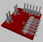
Some eye candy - the latest Beta version of Diptrace offers 3D rendering; not perfect yet (e.g. many footprints don't have associated 3D models, and searching for suitable models is a pain since there is no preview), but after a bit of work - my 6yr old now thinks electronics is the coolest thing! - it gives at least some impression as to how the board will look like. Haven't yet found models for the connectors (BNC, USB, SIP headers) and the jumpers are a kludge as well.

Wolfgang
 

Attachments

womai

Senior Member
Yeah, the silkscreen of the USB connector does go off the board, because the connector will indeed protrude over the board edge so it goes through the cutout in the backpanel.

The 3D rendering quality is indeed superb, but the lack of models for many important parts makes it a bit of a pain (Diptrace is "light" on connector models to say the least - and that goes for the normal footprints as well).
 

Dippy

Moderator
Slight brief aside: check out Proteus. The method for creating DIY 3D components is pretty darned good. In fact, Proteus DIY component creating is the best I've seen.
 

Technical

Technical Support
Staff member
Many PCB software packages offer this 3D view these days - even some of the free ones like DesignSpark now have it
 

womai

Senior Member
For me the question here is - how easy is it to render all the components in 3D, especially ones that don't have PCB-tool provided models already? It's nice if whatever layout tool you use can do rendering, but if creating new models is a pain then it's more a show-off demo feature than a real help. I'm not even asking for super-detailed models necessarily - a block/cylinder of the proper size with maybe cylindrical or square leads either horizontally or vertically would be good enough to get an impression.

Dippy, thanks for the hint with Proteus. I'll give it a try. I don't really want to spend money (and learning time) on a complex 3D design package that I'll use about once a year. Google sketchup is easy but if you want to export to any file format usable by 3rd party tools they make you pay, too. I found a few tutorials showing how to get around that but it's a compicated multi-step conversion process that will make you scream at the second time around I'm afraid.
 

Svejk

Senior Member
@Womai: at the risk it will run off topic, the 3d *.wrl in DipTrace are made with Wings 3D, a free software. The 3 pin header connector in attached photo was made in SolidWorks in about 10 minutes.
 

Attachments

womai

Senior Member
naa, not off-topic for me. I'm going to waste a bit more time on this - does not add much value to the project but it's too much fun to pass on the opportunity ;)

You confused me - first you mention Wings 3D, but then you say you model in SolidWorks? (tthe latter is about as far from "free" as you can get). I'll look up Wings 3D today and see if it works for me.

You would not happen (or be willing to create in a few additional minutes) to have .wrl models for 2-pin header, 6-pin header, and right-angle 6-pin header which you could share?
 

Svejk

Senior Member
Sorry, didn't mean to confuse you: I'm handy with SolidWorks, I've used that to give you an ideea of what sort of time are you looking for creating a simple 3D component. Novarm is using Wings for their rendering, so since is free, I pointed to it.

WRT to creating the models, if you accept them green [I have no time yet to make them coloured], yes, why not. Is 7:30 am got to get the kid ready for school, but I can manage something by this arvo.
 

John West

Senior Member
Not to worry about green pins, Svejk. All of my ancestors are Irish. We love green everything. There, now THAT'S off subject.
 

womai

Senior Member
Yes, a green model that exists is much better than one in color of my choice that does not :) So please do! (you can upload them in a zip file with your next post).

Thanks!
 

womai

Senior Member
Even garden-variety passive scope probes offer 1:10 mode in addition to 1:1. That allows to measure larger signals when necessary. They also tend to easier to attach to your circuit in different ways, and more comfortable to hold when hand-probing. Finally the 1:10 mode reduces the loading on the circuit and offers much higher bandwidth (60 MHz for low-end probes, ub to 300+ MHz for higher-end, more expensive passive probes) - in 1:1 mode or when using a simple coaxial cable the bandwidth is ~5 MHz - but this latter property is of little advantage for a scope that has less than 1 MHz bandwidth itself.
 

greencardigan

Senior Member
Ok. I would prefer the enclosed/BNC option with some inexpensive BNC-to-grabber or BNC-to-micrograbber cables included. That will allow me to easily upgrade to some better probes if the need arises. Keep up the good work.
 
Top