XRF radio modules

ciseco

Senior Member
Stan, many thanks for the offer. We are providing the single option at the moment (looking to the rubber duck and yagi as the next step). We understand people will want to tinker with our kit for sure, the module is for prototyping after all.

Some type of subsidised assistance could be arguably be a condonement of an approach which certainly we have no control of and could have the side effect of falling outside local radio regs. Sounds a sticky wicket, I hope you can see the quandary. We are already attracting attention for releasing something with these capabilities at such a low cost, I'm loathed to give such people more ammunition.

The POE suggestion is a great one, never thought of it that way.We see wireless as the last few meters (maybe hundreds). Going any further, IP is much more suitable and far cheaper solution. Depending on where you shop, some broadband here is free.

Here's a picture of our existing POE gateway with Xbee/XRF socket (top left), it's ARM based and costs a bomb, we are working on a similar thing that'll run on an Arduino/Xino and ENC ethernet equipped shield that people can build for themselves using off the self hardware.

 
Last edited:

Haku

Senior Member
ciseco, I'm just back from Tesco (24h shopping is handy) via another hill:


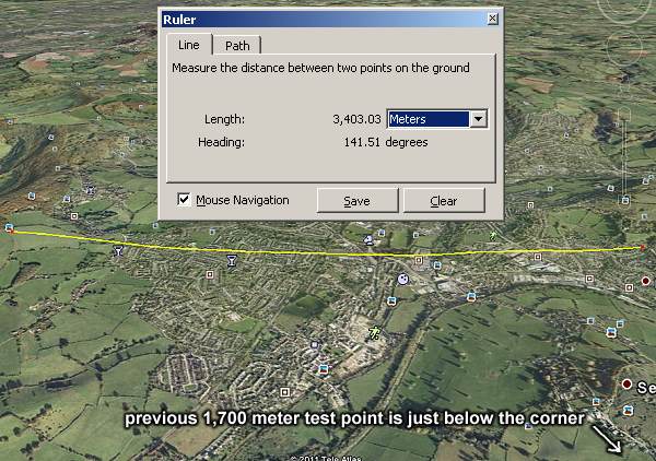
Default whip antennas and settings except for 1.2K radio data rate, 12 character string sent every 1/5 second, achieved approx 10% message loss at 3.4 kilometers (2.11 miles) when the receiving antenna was about 1 meter off the ground and aligned just right.

And your initial goal was 250 meters... :D

I had a module set to 315mhz sending at the same time and took a 315mhz module with me but not a sausage at the distance the 868.3mhz signal achieved tonight.


From my little experience with XBees (series 2) I found them initially difficult to get to grips with because of the settings you have to get right to get two modules to talk to each other, and looking at all the other settings in the manual and the X-CTU software it was a little daunting trying out new things, but the XRF has been easy in comparion to use, especially as they communicate with each other out-of-the-box so you can safely play with the settings in the knowledge you just have to short pins 19 & 20 to reset the module back to a known working state.


edit: Going back to an earlier post of yours, http://www.picaxeforum.co.uk/showpost.php?p=163033&postcount=9 how do you get an XRF to talk to a TI Chronos wristwatch? Now that's something I'd like to be able to do.
 
Last edited:

ciseco

Senior Member
Jaw hits floor!!!! I'm shocked beyond all words.

Was this on your break out board plugged into the breadboard? I ask because the ground plane will "grow" and I wonder if you have hit some sort of sweet spot.

3403 meters is insane.:D

The chronos watch runs a TI CC430 16 bit micro. I got mine from farnell for £36 + vat. How they managed to make it for the price I don't know. It comes with a hardware programmer and USB dongle. I can't seem to find my dongle but I suspect it's almost identical to the USB XRF we are coding now. You'll need to be very handy with C. The free to download TI packet sniffer, you'll be able to see "radiowise" how the XRF data packets are constructed. It's a matter of copying it.

The XRF design is essentially for copying serial data to and from the RF section and back again. If you wanted to use the watch as an "end" device, you'll need to come up with some sort of data structure so you know what device you are talking to. We use a terribly simple 12 byte structure. Link below, you can copy it (the protocol) or make your own. Copying aP would be great, we are doing a series of articles where you'll see how to build an RF temp sensor, RF relay, lightswitch, plant moisture monitor, solar controller, that sort of thing. The logic being the more people who make things that'll talk to other things the possibilities grow exponentially, it's all opensource.

The PICAXE is perfect for this type of thing as it's just basic string handling and useully simple I/O. Even an 08M will work, you leave the data handling, encryption etc to the radio.

http://openmicros.org/index.php/articles/81-xrf-projects/101-aprotocol-starter

Right, I must do some work and stop waffling, must be because I'm all excited, 3404meters, still a big grin:D

Miles
 

John West

Senior Member
I'd be more than happy to trial assorted 900MHz antenna - swap you the findings for a couple of XRFs?

Aside from dish & Yagi style, collinear arrays are quite feasible too. In fact these can even be made from suitably "persuaded" coax cable - refer pix. They're still omnidirectional, but their gain arises from the squashed radiation pattern - no point in wasting signals up into the sky when users are all terrestrial. I've had a lot of mileage with "Slim JIM" versions at VHF & low UHF freqs.

Of course transmission line losses may become significant, so perhaps even consider mounting the entire XRF at the elevated antenna feed point,supplying DC & the data from below. This of course is the PoE (Power over Ethernet) approach used by some 2.4GHz WiFi APs. Stan.
A note on the vertical colinear antennas. Be advised that the quarter wavelength sections must be dimensioned based on the velocity factor of the coax cable used, which will require the sections to be significantly shorter than free-space wavelength calculations would suggest.
 

manuka

Senior Member
Yes-a valid point John! EM wave propagation at the speed of light only applies to free space, & when in conductors signals slow down significantly. As wavelength = vel/freq. the wavelength indeed hence decreases. This is partly why antenna dimensions are often quoted in wavelengths rather than in fixed measurements

The so called velocity factor is ~0.66 for cheap RG59 coax, improving to ~0.75 for superior RG6 type. So at 900 MHz a wavelength in TV grade coax may be shortened from a free space 333 mm to something like 0.66 x 333 = 220mm. Of course using a dish reflector means signals stay entirely wireless & YF issues are incidental...
 

ciseco

Senior Member
Haku

Confirmed, packet length of sub 10 bytes is a "new feature", I have persuaded them in the next release to put it back to one again. Long conversation of payloads and efficiency, anyway boring topic, next revision, it'll be back to it's earlier function.

With the XRF config manager software you can update the firmware, you just need a windows PC and some connection to RX/TX on the XRF (sparkfun xbee adapt, our board, MAX232 etc).

If you want to try the beta version, email PM me your email address. At some point you'll be able to update firmware over the air.

Miles
 

Haku

Senior Member
Jaw hits floor!!!! I'm shocked beyond all words.

Was this on your break out board plugged into the breadboard? I ask because the ground plane will "grow" and I wonder if you have hit some sort of sweet spot.
I thought you might be a little suprised :D I certainly was.

Yes the two transmitting XRFs were on the (usual sized) breadboard with several GND jumper wires and the top+bottom rails also GND, and the board was being powered from a mains adapter with an extension on its output.
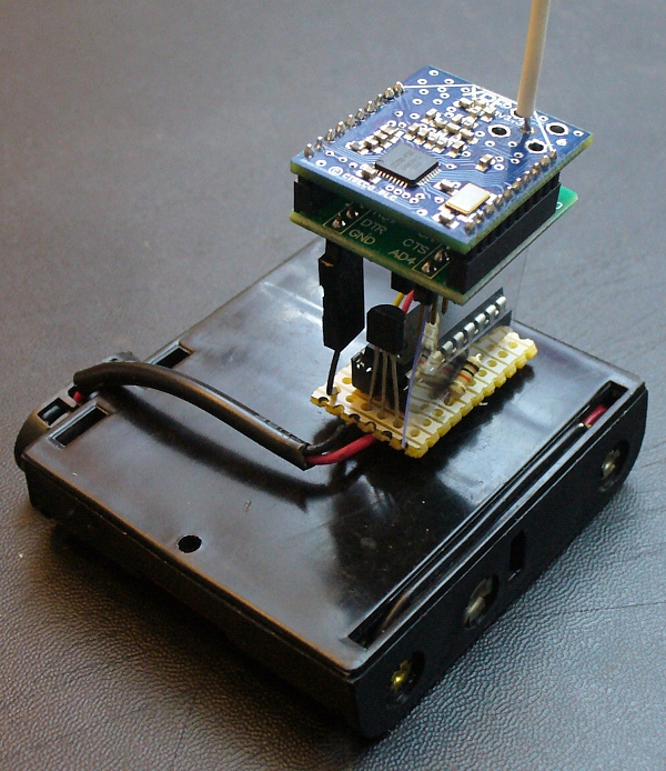
However I've just completed this transmission test setup:


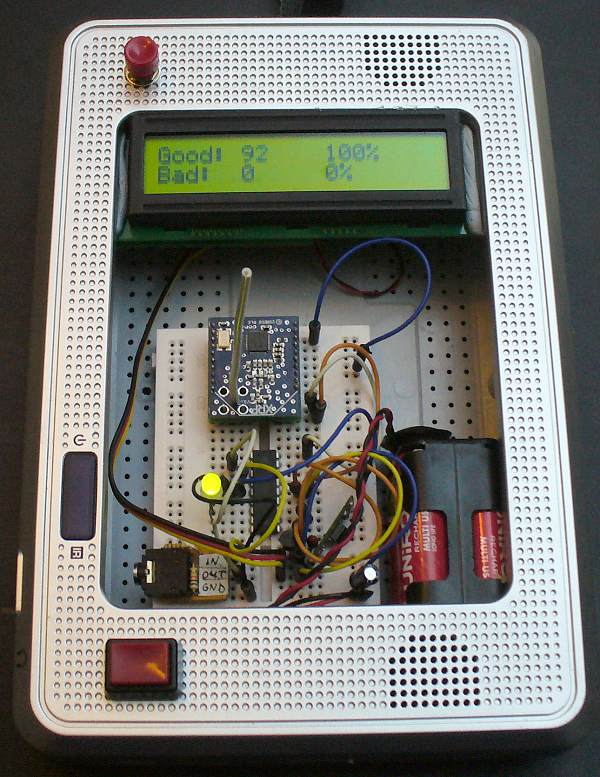
And this is the setup I've been using to take out with me on the tests, the plastic case is from an old LCD video screen, top button does LCD backlight so I can see it at night, bottom button is on/off and there's a red+green LED for instant feedback of being able to receive messages or not:


I certainly would like to beta test the XRF config software, my email address is haku haku co uk (fill in the blanks). If you're taking suggestions for features of the software there's one particular one I'd like:

Being able to alter the terminal display window width with ASCII on left and hex display on right, like the X-CTU software but not do CR or LF just put a "." instead, that way when you're consistantly sending messages of say 12 characters long you can alter the width of the terminal display to 12 characters wide so the upward scroll of previous 12 character messages is vertical not diagonal as with a non-12 character width display.


The Chronos watch, a bit of me was hoping it would be easy to hook into a Picaxe via an XRF, my C skills are pretty much non-existant so learning C and also reverse-engineering the XRF protocol look quite daunting, for the moment I'll stick to just using XRFs for Picaxe-Picaxe comms and slowly building up my RP5 tracked chassis.
On that note I found the XRFs & 18m2s have no problems sending/receiving a 10 character string 80+ times a second (control signal for the RP5) but the 18m2 on the receiving end had a fit when it tried to issue 2 PWM commands at that rate and ended up doing the electronic equivilant of sitting in the corner rocking back and forth so had to be powered off/on :D reduced it down to around 32 times a second and it was happy.
 

Haku

Senior Member
Miles, I've just done a round trip to the 3 main test points, it was a nice cycle ride (my ageing 2 year old ebike battery is flat now), you were on the money with with the ground plane theory, the new test transmitter setup wouldn't reach the 3.4km distance but easily reached the original 1.1km & 1.7km distances with the test rigs pictured in my previous post.

So it might be worth noting in the manual that increasing the ground plane will increase the comms distance. How to accurately test this I don't know, but I'm up for some more cycling if you come up with any good theories, I could do with the excersize :)
 
Last edited:

Haku

Senior Member
I've written a couple of subroutines so you can configure an XRF from a Picaxe and get feedback as to wether the configuring worked, this allows you to permanently short pins 19&20 of the XRF on your project and always end up with the configuration you want, however the configuration will take over 2.2 seconds and this is unavoidable.

It also allows you to check wether the XRF connected to the Picaxe is actually responding simply by using initXRF and then sending ATDN and reading the XRFok value.

Code:
#picaxe 18m2
#no_data

setfreq m16

symbol XRFinput=b.6    'input line of XRF
symbol XRFoutput=b.1   'output line of XRF
symbol XRFat1=b27      'AT command 1st character
symbol XRFat2=b26      'AT command 2nd character
symbol XRFat3=w12      'AT command value, use $FFFF for blank
symbol XRFok=b23       '0=timeout from XRF
                       '1=OK
                       '2=ERR


'example of how to use subroutines:
gosub initXRF
if XRFok=1 then
 'send ATRE (reset to factory defaults)
 XRFat1="R":XRFat2="E":XRFat3=$FFFF:gosub setXRF
 'send ATDR3 (set data rate to 1.2K)
 XRFat1="D":XRFat2="R":XRFat3=3:gosub setXRF
 'send ATDN (exit AT command control mode)
 XRFat1="D":XRFat2="N":XRFat3=$FFFF:gosub setXRF
endif

end


initXRF:          'initialise XRF module's AT command control
 high XRFinput
 pause 4400       'pause 1.1 seconds
 serout XRFinput,T9600_16,("+++")
 pause 4400       'pause 1.1 seconds
 serout XRFinput,T9600_16,("AT",cr)
 gosub checkXRFok
 return

setXRF:           'send an AT command to XRF module
 if XRFat3=$FFFF then
  serout XRFinput,T9600_16,("AT",XRFat1,XRFat2,cr)
 else
  serout XRFinput,T9600_16,("AT",XRFat1,XRFat2,#XRFat3,cr)
 endif
checkXRFok:       'check response from AT command
 serin [800],XRFoutput,T9600_16,XRFat1,XRFat2
 XRFok=0
 if XRFat1="O" and XRFat2="K" then:XRFok=1:endif
 if XRFat1="E" and XRFat2="R" then:XRFok=2:endif
 return
Oddly couldn't get the code to work at 8mhz using normal serin/serout, if you alter the code to use hserin/hserout then any clock speed should be viable. If you do use a different clock speed then you'll need to change the baud rate on the serin/serout commands, and the pause commands so they're still 1.1 seconds long.
 
Last edited:

ciseco

Senior Member
Hi,

I'll pop the application over to you shortly, I'm currently in France and this connection is terribly slow.

Cheers

Miles
 
Top