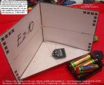
I got some XRF radio modules today, they worked out-of-the-box as advertised (although i didn't actually receive them in a box ") ) so no having to waste time configuring them on the first run, and have been testing a couple on my RP5 tracked chassis setup.
) so no having to waste time configuring them on the first run, and have been testing a couple on my RP5 tracked chassis setup.
Some observations & questions:
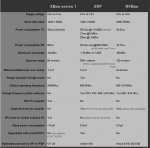
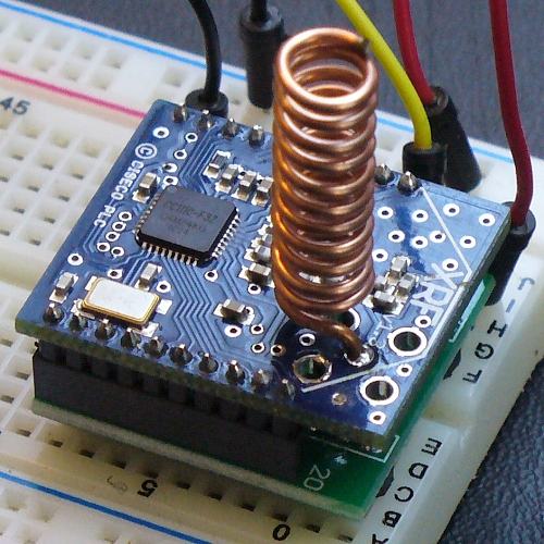
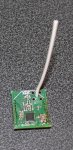
Components wise it looks pretty scarce compared to an XBee - could be made even smaller if only power/signal/reset lines were used?
One welcome feature is that there's virtually no time between powering one up and being able to transmit/recieve data unlike the XBees which take a few seconds to boot up.
Would've been nice to have a link to this page on the auction listing for the AT command set: http://www.ciseco.co.uk/content/?p=1738
The X-CTU software from Digi is useful for setting AT commands (much better than HyperTerminal which can be a right royal pain in the backside to use) and when you do press the "Test / Query" button it actually returns some info, which is a useful test to see that the module is running.
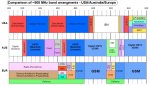
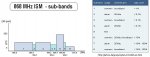
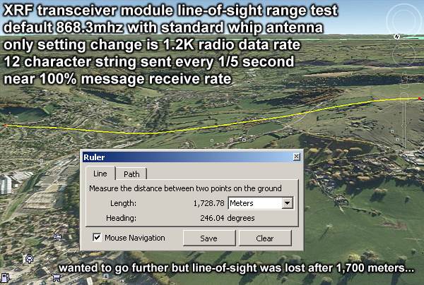
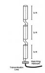
The whip antennas that came with it are around 82-83mm including the bit that goes through the board and gets soldered which is appropriate for the default 868.3MHz comms frequency, but if I want to run at a different frequency, which is best, 1/2 or 1/4 wave length antenna? and what's the difference between the different fractions of lengths in terms of signal strength?
Baud rates; I'm running at the default 9600 rate and am having to code the receiving end to cope with not receiving data after X microseconds, if I increase the rate will this help keep things smoother?
The transmitter end of my setup is continually reading from two potentiometers, doing a bit of calculation and then spitting out resulting data to the radio, all running as fast as it can at 32mhz.
What effects does changing the Radio Data Rate have on transmitting/receiving? Should I just leave it be?
So far I'm fairly impressed with them, mainly as they didn't need any configuring and could be used straight away, however I notice the auction listing has changed since I bought them to say that the price is introductory, I hope this doesn't mean the price will rise to that of an XBee because I think it wouldn't help sales as potential customers would see the XBee as a reliable option. I would like to see these boards sold in the thousands so the price goes down not up
) so no having to waste time configuring them on the first run, and have been testing a couple on my RP5 tracked chassis setup.Some observations & questions:
Components wise it looks pretty scarce compared to an XBee - could be made even smaller if only power/signal/reset lines were used?
One welcome feature is that there's virtually no time between powering one up and being able to transmit/recieve data unlike the XBees which take a few seconds to boot up.
Would've been nice to have a link to this page on the auction listing for the AT command set: http://www.ciseco.co.uk/content/?p=1738
The X-CTU software from Digi is useful for setting AT commands (much better than HyperTerminal which can be a right royal pain in the backside to use) and when you do press the "Test / Query" button it actually returns some info, which is a useful test to see that the module is running.
The whip antennas that came with it are around 82-83mm including the bit that goes through the board and gets soldered which is appropriate for the default 868.3MHz comms frequency, but if I want to run at a different frequency, which is best, 1/2 or 1/4 wave length antenna? and what's the difference between the different fractions of lengths in terms of signal strength?
Baud rates; I'm running at the default 9600 rate and am having to code the receiving end to cope with not receiving data after X microseconds, if I increase the rate will this help keep things smoother?
The transmitter end of my setup is continually reading from two potentiometers, doing a bit of calculation and then spitting out resulting data to the radio, all running as fast as it can at 32mhz.
What effects does changing the Radio Data Rate have on transmitting/receiving? Should I just leave it be?
So far I'm fairly impressed with them, mainly as they didn't need any configuring and could be used straight away, however I notice the auction listing has changed since I bought them to say that the price is introductory, I hope this doesn't mean the price will rise to that of an XBee because I think it wouldn't help sales as potential customers would see the XBee as a reliable option. I would like to see these boards sold in the thousands so the price goes down not up