UV lightbox cheap equivalents?
- Thread starter alband
- Start date
I'm no medical Dr but thats a slight mis-reading. Sun tanning is not cancer in any way, its a cell response to the UV that produces more of the exact same chemical that makes coloured people brown, melanin. Excessive exposure causes cell nucleus DAMAGE which leads to cancer eventually.sun tan is mild skin cancer
Yes it does. And sun cream is just a partial filter, full block DOES leave you untanned.UV does not cause a sun tan. If it did then going on holiday twice a year would cause skin cancer or using sun cream would leave people untanned.
Certain glasses do to a great extent, but I've ended up with sunburn from behind a closed car window before now. More modern cars have better UV filtering to make car interiors last longer. House windows also use the same barrier technology.i always thought glass blocked UV, thats why you cant get sun-tanned sitting inside.
Back on topic - I've found a source of 21w magnetic balasts to run my UV lamps, 4 for £5. Brilliant.
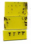
Just out of idle curiosity, I tried the following:
FR4 board / Metasilicate developer/ Ferric Chloride etchant.
I wrote letters on thin polythene, and taped them to the boards.
(probably imperfect registration).
Exposure 1. A powerful flashgun, on full output, from c. 2cm
Exposure 2. Two 8mm UV LED's
http://www.rapidonline.com/Electronic-Components/Optoelectronics/8mm-LEDs/8mm-water-clear-LEDs/78767/kw/55-2214
~20mA current each, pointed at the centre of the board..
About 10 minutes exposure, 1cm distance
Exposure 3. An ultraviolet lantern, similar to this
http://www.maplin.co.uk/Module.aspx?ModuleNo=2040
about two minutes exposure, at c.2 cm distance.
Processing.
No exact dilution measurements or temperature control.
Results.
Flash (F) = overexposure c/w overdevelopment?
LED (L) = Overexposure directly below the lens.
Blacklight Tube. (T) Surprisingly good.
And all at 6volts. (Except for boiling the kettle!)
These are neither recommendations, nor scientific tests.
But, if anyone's got any photoboard off-cuts,
it might be worth a play?
e.
Attachments
-
 25 KB Views: 24
Last edited:
An interesting experiment. Results don't look too good though 
Surely, for a simple PCB exposure box, the bottom line is consistent and perfectly even UV lighting spread.
When I were a lad I made one from a starter/ballast thing and a replacement UV tube from RS Components. I put it in a box with 3mm float glass and a switch - no safety interlocks but couldn't be much simpler. Fine for small boards.
Pukka 'entry level' boxes aren't much more than that, but with a lid-open-safety-OFF-switch and a timer and some fancy reflector for even distribution. Usually 2 or 4 tubes.
For prototyping nowadays I use a £100 Farnell jobby. I still expose for 1.5 minutes onto FR4 (Fotoboard) and have excellent results. It's been used gallons of times over the last 10 years with no noticeable degradation.
I really can't see how you can ever get evenly-spread distribution with a UV LED unless you have some fancy scanning method. LED optics are usually pretty grim.
And a PCB with <0.3mm tracks requires excellent UV distribution for consistent results.
Otherwise you'll get bald patches. And at £x per board wastage you may as well spend £120 on something that works
I'd like a thing like a laser printer but with UV and just run the board through.
And talking of boiling kettles... its time for a cuppa.
@Dippy.
I agree with all your comments.
If I needed to make boards,
then I'd buy a "real" UV exposure unit.
My playing was just to check if
electronic flash or "black" UV worked.
They do.
But not well enough to produce consistent, usable circuit boards.
Edit-add.
Unless some clever, dedicated sprog can surprise/amaze everyone.
e
Last edited:
Yes, fair enough. Its a good test.
And a flash exposure would certainly save time. Can you hang things around a flash tube (or tubes) to get a dead even spread?
Obv. with a bit of electronic (PICAXE controlled?) jiggery pokery you can adjust flash energy. (Or just move the tube further away ).
You may be onto something there. See you in Dragon's Den ?
And a flash exposure would certainly save time. Can you hang things around a flash tube (or tubes) to get a dead even spread?
Obv. with a bit of electronic (PICAXE controlled?) jiggery pokery you can adjust flash energy. (Or just move the tube further away
).You may be onto something there. See you in Dragon's Den ?
(Picaxe)- Flash, bang, wallop, ........
But, chucking in some ideas from photography:
Light tent.
Flash box.
Flash brolly.
Enlarger diffuser box.
e
I genuinely don't know about the absolute even spread of light.Yes, fair enough. Its a good test.
And a flash exposure would certainly save time. Can you hang things around a flash tube (or tubes) to get a dead even spread?
Obv. with a bit of electronic (PICAXE controlled?) jiggery pokery you can adjust flash energy. (Or just move the tube further away
You may be onto something there. See you in Dragon's Den ?
But, chucking in some ideas from photography:
Light tent.
Flash box.
Flash brolly.
Enlarger diffuser box.
e
Sorry, you've lost me.
Why do you want to use that great pile of stuff?
Why not a few flash tubes (+gubbins) in a box with a glass top and fold down lid?
I'm sure we can think of something better than crumpled foil for a reflector
Check out the refelctors used in proper boxes.
Maybe in conjuction with a diffusing thing.
It could look like a proper exposure box. Instead of a timer on the front you could have a knob to set the energy.
But feel free to fit a brolly on the top and inside a tent if you want .... hee hee.
A portable, fast exposure box - now that appeals. No mains. Nice. (Assuming it works).
I'm suffering Shrudlu today.Sorry, you've lost me.
Why do you want to use that great pile of stuff?
Why not a few flash tubes (+gubbins) in a box with a glass top and fold down lid?
I'm sure we can think of something better than crumpled foil for a reflector
Check out the refelctors used in proper boxes.
Maybe in conjuction with a diffusing thing.
It could look like a proper exposure box. Instead of a timer on the front you could have a knob to set the energy.
But feel free to fit a brolly on the top and inside a tent if you want .... hee hee.
A portable, fast exposure box - now that appeals. No mains. Nice. (Assuming it works).
A single / simple electronic flashgun. No tubes or controllers..
6V powered. Easy to trigger.
A simple reflector/diffuser system, in an appropriate box, of appropriate size.
e
Off for a lie down.
Last edited:
Thats the kind of thing.
You may wish energy control one day as different board manufs need different exposures and also to allow for different transparency of different print media.
(Could just be simply different number of flashes).
None of this should be too hard as the variable flash energy is easy current technology used in zillions of cameras and flashguns.
Sounds good - go for it.
incandescent light bulbs?
Hi all,
just wanted to remark that I successfully etched a small PCB using some kind of incandescent light bulb for exposure. No UV tubes were used..
- for exposure I used 10cm distance PCB to bulb for 18 minutes
- development was done using 1.5g NAoh / 120 ml water
- etching was done using some grams of persulfate in some water (didn't measure)
I'm very pleased with the results, although I did just cut out the traces by hand using a sharp knife... (of course you cals also print your layout onto some transparent laser printer paper but I wanted to be ghetto about it! )


I'm in a hurry so thats all now but I think you can see that UV light isn't needed for exposure...
cheers
EDIT As it turns out there IS a small amnt of UV light emitted from this CFL shown above, as can be seen in the following posts. I stand corrected.
Hi all,
just wanted to remark that I successfully etched a small PCB using some kind of incandescent light bulb for exposure. No UV tubes were used..
- for exposure I used 10cm distance PCB to bulb for 18 minutes
- development was done using 1.5g NAoh / 120 ml water
- etching was done using some grams of persulfate in some water (didn't measure)
I'm very pleased with the results, although I did just cut out the traces by hand using a sharp knife... (of course you cals also print your layout onto some transparent laser printer paper but I wanted to be ghetto about it!
)
I'm in a hurry so thats all now but I think you can see that UV light isn't needed for exposure...
cheers
EDIT As it turns out there IS a small amnt of UV light emitted from this CFL shown above, as can be seen in the following posts. I stand corrected.
Last edited:
Andrew Cowan
Senior Member
There was a health scare a while back about the amount of UV that those compact florescent tubes give out. They summarised that you have an increased risk of skin cancer if you regularly work less than 30cm away from one. ie they do give out more UV than a regular bulb.
A
A
Yes, I read something about UV from fluorescents too. Long tube and CFLs.
I was amazed by AIC etting 'incandescents' to work - fortunately he posted a picture showing a fluor and not incand light.
I'm going stand in front of my CFLs for a while and see if I can get a nice tan.
Having said that, I just read this on GE site:
"The amount of UV produced by standard fluorescent lamps, such as those in your office, home, or school, is not hazardous and does not pose a major health concern. In fact, a paper by the National Electrical Manufacturers Association (NEMA) explores this subject in more detail. It cites a study in which it was determined that UV exposure from sitting indoors under fluorescent lights at typical office light levels for an eight-hour workday is equivalent to just over a minute of exposure to the sun in Washington, D.C. on a clear day in July."
Maybe I'll stand in the sun instead
Having said that, if AIC's CFL can expose OK in 18 minutes @ 10cm and your average light-box is 1.5 minutes @ 3 or 4cm .... mmm... makes you wonder don't it. Doesn't it?
Lordy lordy, I must get out more....
Last edited:
Do you mean Solder RESIST screen or solder paste screen for surface mount?
Either mthod will require a screen to be made, whther for screen-print (squeegee) or spray.
You'd better Google around as I think 'solder resist' is a pretty tough epoxy or something like that?
Normally you'd only plug holes when doing wave soldering, but the usual mthod is that rubbery stuff that looks like Copydex glue, or silicon rubber bungs 9conical shaped things).
So what I've got is a fluorescent light bulb there? I wasn't sure - where I live this thing is just called "energy saving bulb". Good to know.
Interesting thing is, the etching is VERY accurate - even without any kind of diffusor!
I plan to build an exposure box too with two or three of these babies.
Do you think I should try to expose with even less distance between bulb and PCB (you mention 3-4cm)?
thanks
Interesting thing is, the etching is VERY accurate - even without any kind of diffusor!
I plan to build an exposure box too with two or three of these babies.
Do you think I should try to expose with even less distance between bulb and PCB (you mention 3-4cm)?
thanks
"Low Energy" or "Energy Saving" bulbs tend to be CFL = Compact Fluorescent Lamp/Light.
Do I think? (Not often ) - I can only suggest that you have a go.
Just remember that the extra distance 'evened up' the light distribution. The closer you get then the less even it will be i.e. concentrated towards the middle.
Proper UV boxes have a stippled pressed shiny metal reflector to even things up.
(as opposed to scrunched up al. foil )
The quality of your etching is related to with the quality of your 'negative' as much as anything else.
You may find a 1" square exposes/etches wonderfully, but a 6x4" board is great in the middle and lousy at the edges. If that happens then its obv the UV distribution of your exposure box at fault.
Do I think? (Not often
) - I can only suggest that you have a go.Just remember that the extra distance 'evened up' the light distribution. The closer you get then the less even it will be i.e. concentrated towards the middle.
Proper UV boxes have a stippled pressed shiny metal reflector to even things up.
(as opposed to scrunched up al. foil
)The quality of your etching is related to with the quality of your 'negative' as much as anything else.
You may find a 1" square exposes/etches wonderfully, but a 6x4" board is great in the middle and lousy at the edges. If that happens then its obv the UV distribution of your exposure box at fault.
@AICHi all,
just wanted to remark that I successfully etched a small PCB using some kind of incandescent light bulb for exposure. No UV tubes were used..
- for exposure I used 10cm distance PCB to bulb for 18 minutes
- development was done using 1.5g NAoh / 120 ml water
- etching was done using some grams of persulfate in some water (didn't measure)
I'm very pleased with the results, although I did just cut out the traces by hand using a sharp knife... (of course you cals also print your layout onto some transparent laser printer paper but I wanted to be ghetto about it!
I'm in a hurry so thats all now but I think you can see that UV light isn't needed for exposure...
cheers
Sorry, but I'm confused as usual.
What did you use for the negative mask?
Why was cutting the traces needed?
e
Andrew Cowan
Senior Member
I presume he cut the traces in the black film that comes on the board. I often do that when developing a tiny PCB on a small board (to save etchant).
A
A

yes I plan to use ordinary mask printed on laserprinter overhead foil next time too.
It just is too much work for a real pcb to cut the traces by hand if I think about 28pin sockets and such
Anyway for a quick exposure/development/etching time test this worked well.
@Dippy: I found that if the board is not evenly developed/etched, either agitation is not sufficent (stir up a bit more) and/or concentration is too high (dilute with a bit water). The larger a board, the slower the process has to be conducted to achieve even results (provided exposure was good and even too)
Last edited:
Thanks for tips...
I've been doing proto boards for many years now and have settled on using a proper UV box, laser print onto OHP or similar transparent film and using a bubble etcher.
I tend to use Fotoboard 2 FR4, Seno 4006 developer and Sodium Persulphate etcher.
Ferric Chloride is faster but is smelly and stainy. Many stains can be removed with Oxalic acid.
Typical times:
Exposure 1.5 mins
Develop 30 seconds
Etch @ 40oC 10 to 20 minutes depending on state of etcher.
Oh so you are not really in need of etching advice anymore.
30 seconds developing time is FAST. Is that "Seno 4006" specialty stuff?
(I heard of sodium metasilcate that you can't overdevelop with this stuff - is this what your using?)
And do you use a bubble etch tank or do you stir/agitate by hand? (20 minutes is rather slow etching which is good for large baords)
EDIT nevermind the etch tank question just read you have bubble etch sry
Last edited:
I get SENO from Mega Electronics.
Its very concentrated. For Fotoboard 2 25ml is mixed with ~450ml tepid water for a working solution.
So it goes quite a long way.
Ferric Chloride is almost twice as quick.
Slow etching is NOT good as the etcher gets under the photo resist. Thin (<0.4mm) tracks can be etched out if done too slowly or without aggitation.
I just experimented until I got a consistent result and then use the same times/concentrations/temps thereafter. It rarely fails.
I meant slow as in "low concentration etchant"
strong etchant crawls further under the photoresist in shorter time compared to "weak" etchant solutions
Anyway as long as it works who cares, I guess everyone has to figure what works best for him/her and then use that, as you said.
Speaking of fast etching, did you ever try etching with persulf at 60°C?
Last edited:
I think 40 is the optimum working temp, I believe it breaks down at temps above 45 deg C...i'm sure I read that somewheredid you ever try etching with persulf at 60°C?
Right, sorry I haven't replied for a while...
I still haven't ordered the LED's but am wondering if I should in light of eclectic's discoveries using them.
As suggested though by MartinM57, I could just drill or cut off the tips of them to get rid of the directionality. Should I still stick with the LED's or move back to the light tubes?
I still haven't ordered the LED's but am wondering if I should in light of eclectic's discoveries using them.
As suggested though by MartinM57, I could just drill or cut off the tips of them to get rid of the directionality. Should I still stick with the LED's or move back to the light tubes?
David. How much money have you got?Right, sorry I haven't replied for a while...
I still haven't ordered the LED's but am wondering if I should in light of eclectic's discoveries using them.
As suggested though by MartinM57, I could just drill or cut off the tips of them to get rid of the directionality. Should I still stick with the LED's or move back to the light tubes?
Lots = Buy a real, PROVEN, lightbox.
Less. Then experiment, but don't expect anything.
e
I'll go along with ec.
Alband, as said before, it's all about even distribution of UV, consistency and reproducibility - assuming you want to be able to shove a 'blank' PCB and get guaranteed results.
I'm sure that with enough UV LEDs and enough time spent you can get it to work.
I'm sure with a tube (+gubbins) you could have something working within a couple of hours.
I don't know how good your DIY is so the quality of the finished product is down to you.
If you want fine boards esp larger ones you will have to put in the extra work and expense to make something good.
Can't you get a ready made one for a fiver from the (apparently) top quality source commonly known as Ebay?
Note: If you find that you need 10 minute exposure times I will guarantee that after a while this will drive you nuts - or maybe its because I'm an impatient so&so.
If you've got the time then have a go at various things otherwise this will just go round and round.
Right, unfortunately, there is a budget issue .
Also unfortunately, I'd already checked the Bay and this is all they have. I might see if I can get the second one for a small sum but Bedfordshire isn't exactly local.
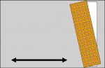
If I can't get those (i.e. they've put a reserve on it) then I think I will go for the LED's with the following "plan":
I only want to do small boards
I have a few friends who might be able to give me an old, bust up scanner and I've got some nice stripboard.
I get the LED's in a grid of 20 across the scanner (perpendicular to the direction it moves) and 5 along.
Heat up some scrap, sheet metal on the hob and press the tips against it it should flatten them all without danger of breaking the dice.
Crucially though, I would mount them on the scanner at a slight angle so that there would be no possibility of "lines" of less-exposed copper.
I wouldn't mind waiting a bit for it to work either.
Of course it should be quite possible to replace the LED's with a UV tube if needs be.
Thanks.
.Also unfortunately, I'd already checked the Bay and this is all they have. I might see if I can get the second one for a small sum but Bedfordshire isn't exactly local.
If I can't get those (i.e. they've put a reserve on it) then I think I will go for the LED's with the following "plan":
I only want to do small boards
I have a few friends who might be able to give me an old, bust up scanner and I've got some nice stripboard.
I get the LED's in a grid of 20 across the scanner (perpendicular to the direction it moves) and 5 along.
Heat up some scrap, sheet metal on the hob and press the tips against it it should flatten them all without danger of breaking the dice.
Crucially though, I would mount them on the scanner at a slight angle so that there would be no possibility of "lines" of less-exposed copper.
I wouldn't mind waiting a bit for it to work either.
Of course it should be quite possible to replace the LED's with a UV tube if needs be.
Thanks.
Attachments
-
 41.5 KB Views: 12
You really need to remove the dome on the LEDs, not just "squidge" it down. Where will the excess material go? Also, you'll probably end up with 100 LEDs stuck to a hot piece of metalHeat up some scrap, sheet metal on the hob and press the tips against it it should flatten them all without danger of breaking the dice.
You also need a fairly good 'polished' surface - a sanding drum on a dremel is ideal, but you could, maybe, find a suitably thick piece of wood, drill suitably sized holes and put the LEDs in so that the dome is above the surface by the right amount and then just sand the domes off (somehow)
Do some experiments first to see how much to remove - wire up one LED and point it at your hand (not eye!) at the distance they will be from the PCB in the scanner and see how focussed the light is. Gradually remove the dome and retest - you'll see the focus goes down, but so does the intensity. Stop when you think you've got the right amount - and repeat 98 times (you'll probably have to ruin one LED by going too far...)
Also, you'll probably end up with 100 LEDs stuck to a hot piece of metal
Good point.
I do have a dremel so that sounds possible (and boring
, oh well, needs must)westaust55
Moderator
UV lightbox cheap equivalents
Years ago, in the aim of economy, I purchased a medical UV sterilisation fluro lamp which I built into a box.
Could still be a very economic path to try.
It was the right wavelength and used for both PCB etching process and EPROM erasing (remember 2708's in purple ceramic format with gold wires and gold plated legs)
BeanieBots
Moderator
And three different power rails
westaust55
Moderator
even more if you wanted to "Burn" them.And three different power rails
Vss = 0V (pin 12)
Vcc = +5V (pin 24)
Vbb = -5V (pin 21)
Vdd = +12V (pin 19)
Program = +26V (pin 18)
Mind you old "Computer"/microprocessor systems needed +/-5V +/-12V so just generated the +26V from the +12V supply.