UV lightbox cheap equivalents?

Andrew Cowan

Senior Member
Develop

The brown stuff is ferric chloride. Long shelf life, works when cold, very messy. Lots of us on here use 'clear stuff' (something theosulphate?), which needs to be hot, but is faster and cleaner.

Resist strip

Bit of developer in a tray. Cheap and simple and fast. Get it from rapid cheaply.

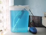
Bubble etch (heated)

Option 1 - tray. Cold, little agitation. Slow, cheap.
Option 2 - homemade tank. Fishtank heater, aquarium pump for bubbles. Fast, cheapish, good results.
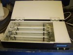
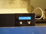
Option 3 - very expensive bubble etch tank. Fast.

Tin wash

Coats the boards in tin. We've never done it at school, makes it more resistant to corrosion. I wouldn't bother.

Hope this helps!

Maybe £15 for all chemicals?
 

chigley

Senior Member
[...]

Hope this helps!

Maybe £15 for all chemicals?
It all sounds like a bit of a faff! Our develop chemical is purple in college, why are there so many different colours? Purple, brown, clear... etc. Do you do them in that order? In college we do bubble etch before resist strip.

£15 for the chemicals sounds more than reasonable, not sure what the best solution for the bubble etch is though.
 

Andrew Cowan

Senior Member
Really? Surely you have to get rid of the etch resist before you etch?

I found a really simple way to make PCBs quickly, but it is rather dangerous.

- UV expose a board
- Stick it in etch resist for 20 seconds.
- PUT ON NEW LATEX GLOVES
- Put some ferric chloride (brown stuff) in a tray
- Dip a sponge in the ferric chloride, and rub on the PCB
- Do this repeatedly
- After about 30 seconds of rubbing, your PCB will be fully etched.
- Dispose of everything responsibly.

Proffesional industry etches PCBs using spray machines, rather like pressure washing. Etches the PCB within a few seconds.

This is probably rather dangerous, but as weak as you wear gloves and work in a well ventilated area, it hasn't caused me any problems. <twitch>.

A
 

chigley

Senior Member
Really? Surely you have to get rid of the etch resist before you etch?
Below is a photograph of the "etching station" where all the chemicals are in college. We go across left to right in the order that you can see. Develop -> Wash -> Bubble Etch -> Wash -> Resist Strip -> Wash -> Immerse Tin


alband

Senior Member
@ eclectic: Yeah sure, but it'll probably be a month until I have anything, also what do you mean by an electronic flash? - Like in a camera?

@ chigley: damn, I didn't notice that, but I probably wont be getting this stuff for a week or two anyway so that is no matter. I would use maplin but they are more expensive and my closest one is very close.

@ Andrew: are you sure the ferric chloride is the developer. The system I'm used to is: Laser print onto tracing paper-like stuff, UV "photograph", develop, using alkali solution, then etch using ferric chloride, then tin (if wanted, I agree it isn't often worth it unless you are storing them for a long time).

@ All: Should about 300 8mm'ers spaced out 10mm apart be good enough?
 

alband

Senior Member
Currently its this, I'm borrowing the schools equipment, but I am planning on getting my own try and leave it using ferric chloride.

Attached is my rapid shopping basket of what I reckon I'll need.
 

Attachments

kevrus

New Member
The 'clear' etchant is sodium persulphate, it's only clear when first mixed into solution. I used a plastic cereal box, aquarium heater and air pump. Etching PCBs turns it a nice shade of blue. As Andrew says, it works best when its heated (35 to 40 deg C). Its less messy than ferric chloride.
 

Attachments

chigley

Senior Member
The 'clear' etchant is sodium persulphate, it's only clear when first mixed into solution. I used a plastic cereal box, aquarium heater and air pump. Etching PCBs turns it a nice shade of blue. As Andrew says, it works best when its heated (35 to 40 deg C). Its less messy than ferric chloride.
What a bizarre but good idea! Do you drain the chemical away after each use, or store it in the same box and use it multiple times?
 

kevrus

New Member
I dont etch a great many boards, but ive found the shelf life to be at least 7 or 8 months. Not sure how that compares with ferric chloride.

Here's a couple of pics of my light box...wish I thought of using an old scanner before making this...
 

Attachments

chigley

Senior Member
I've just managed to dig out an old scanner. I'm thinking about gutting it and attaching a few rows of UV LEDs to the strip which is pushed forwards and backwards during operation. If I wanted to do this, how would I go about using the motor which is already in place inside the scanner? How would I find out what current/voltage it needs to run etc.? Would be PICAXE controlled of course :)

@hippy - is that true? What would happen to it?
 

Mycroft2152

Senior Member
Don't plastics suffer from UV exposure ?
Plastics do, as well as paint.

It also depends on the additives (pigments and UV inihibitors) added to the formualation.

But we are talking about intermittent use here, not long term exposure as in outdoor sunlight.

Probably not relevant.
 

QuIcK

Senior Member
i always thought glass blocked UV, thats why you cant get sun-tanned sitting inside. Mayb theres a special kind fo glass for such applications (do greenhouses need special glass?)
and yes, plastics go browny-yellow(i think), mayb different colours. think of really old striplights with plastic covers on them. theyre always an off-cream colour of brown. like really bad 70s decor.
 

MartinM57

Moderator
- 100 UV LEDs from China on the 'Bay for about £7 delivered
- 5 seconds on each with a Dremel and a sanding drum to take 2-3mm the top of the 'lens' (so the directionality goes away)...
- wire up the LEDs as 25 parallel sets of 4 in series - so no resistors needed when using a bench power supply set at 13.7 which maximises brightness (interestingly as the voltage goes above 13.7v the visible brightness decreases)

...job's a goodun.
 

QuIcK

Senior Member
(interastingly as the voltage goes above 13.7v the visible brightness decreases)
avalanche breakdown of a p-n junction? i just finished a module at uni on semiconductors. most of it was in-one-ear-and-out-the-other, i remeber the lecturer saying something bout that, and i thought it sounded like a cool thing to drop into a conversation at some point...
i think its because they are about to fall over. there is a voltage that will be damaging them, but is reversible if only for a short while. much beyond that and they'll go kaput
edit: messing around with an led. running at 2-2.2v is fine. pushing to 3v its quite bright, draws 100mA, but i dont think its appreciating it. 3.5v looks like the intensity is where it was with 2-2.2v. 5v it starts freaking out, and dies
 
Last edited:

Coyoteboy

Senior Member
Hmm I'm just in the middle of constructing my own one of these using 4x 9w Nail curing UV bulbs (must be the right type, came with warnings about looking at the bulbs directly but no wavelength spec'd). I picked them up for a couple of quid a while ago. I'm just trying to nail how to wire them with a normal magnetic or electronic ballast - each lamp has 2 pins (theyre a G23 format bulb, single U tube with only 2 pins) to I'm trying to work out if I can run 4 of them, in 2 sets of 2 in parallel off the output of 2x36W ballast. AC/Fluorescent lamps are not my forte - anyone advise me/point me at a URL?
 

BeanieBots

Moderator
Fluorescent lamps need FOUR pins.
Two heaters, one at each end.
The heaters come on to evaporate the mercury.
Then a large voltage (several kV) is struck between the two heaters to cause an arc.
Once the arc has struck, a plasma is formed which conducts at much lower voltage (~30v - 100v), the ballast inductively soaks up the difference between mains and plasma voltage.

Don't know how you would do that with just two pins.

Are you sure they are fluorescent lamps.
Maybe they need a more specialised ballast.
Maybe they are cold cathode. (I don't know how to drive them)
 

Andrew Cowan

Senior Member
Cold cathode = just stick a VERY high voltage across the pins. Like 10kV.

But best to work out what they are before you start poking.

A
 

Andrew Cowan

Senior Member
That 'magic' box looks like it might have some electronics inside. Prehaps they just plug straight into the mains? (Don't try without further advice)?
 

Coyoteboy

Senior Member
OK according to the Wiki on CFLs it looks like they're non-integrated (ballast separate) but the starter is built into the fat base section. Definitely only 2 pins though. So it presumably works in this configuration, with the 2 pins being the lower two shown on the lamp in this diagram:


but I'm not sure how that relates to the outputs on a normal ballast. I've not thought hard about it yet though!
 

kevrus

New Member
Can you post a pic of the lamps...some fluorescents have a built-in starter hence only two pins visible...Thorn 2D lamps are an example...they are available with 2 or 4 pins..


whoops
just seen your link for the lamp...these are normally run from a high frequency ballast, not sure if they have built in starters or not..I will try and find out
 
Last edited:

Coyoteboy

Senior Member
Cheers. I was under the impression that the high frequency ballasts were simply to make starting faster and easier and to get up to full brightness quicker, while being noiseless, but I could be wrong (often am!).
 

kevrus

New Member
Running at approx 35 to 40kHz, they reduce flicker, improve starting, increase lamp life and improve efficiency, higher light output is also possible when used with newer generation tubes....they also cost more
 

Coyoteboy

Senior Member
As I suspected. Dont much care about any of those, it's something I wont be looking at, wont be needing to be extending lamp life much - so long as using a normal one doesnt reduce lamp life to minutes!
 

kevrus

New Member
Coyoteboy, I think you will find that your lamps have a built in starter, so you would connect one pin to neutral, and the other pin to one side of your ballast, the otherside of the ballast connecting to live.

It ispossible to run two tubes from one ballast by connecting the tubes in series...this usually involves using aballast rated at twice the single lamp wattage and fitting 110v starters across each lamp...as yours are built in, only experimentation will tell if this would work...I may try this when i'm back at work (weekend)
 

Coyoteboy

Senior Member
cheers for the replies.

So presumably, if electronic ballasts cant cope with having a starter involved, I have 3 choices, in order of preference.

Use a 4x 14w electronic ballast, hack the ends off the lamps and short out the starters, then connect as you suggest live>ballast>lamp>neutral.

EDIT ^^ Being a bit dumb there, if I strap out the starters I effectively have access to all 4 pins anyway and might as well wire as normal.

Use my 2x 36W normal ballast, experiment to see if it copes with series lamps as I cant easily change the starters.

Strap out the 240v starters and replace with 110s.
 
Last edited:

kevrus

New Member
Use a 4x 14w electronic ballast, hack the ends off the lamps and short out the starters, then connect as you suggest live>ballast>lamp>neutral.
live>ballast>lamp>neutral would be for a standard 'wound inductor' ballast.

to use an electronic ballast, if you hacked off the ends of the lamps, you wouldnt short out the starter, you would remove it and connect the open ends to the electronic ballast as per diagram on the ballast, noting that some electronic ballasts do not require all 4 connections,,,in this case you would leave that end/pin unconnected (but safe)

A 2x36w ballast suggests to me to be an electronic one...how many connections are there (should only be two for a standard wound ballast)

just seen your edit
 

Coyoteboy

Senior Member
OK I'm grasping this now I think :) I'm going to have to double check my ballasts when I get home and see what I have! (Or just order 4 ultra-cheapo 1x9w+ ballasts off ebay!)
 

BeanieBots

Moderator
I guess it depends on the wavelength and type of glass.
My EPROM eraser makes regular window glass (and spectacles) glow green, so I guess very little of the UV actually gets through.
 
Top