Tank filler...

Mike.

Member
Hi friends,
I am hobbits in electronics..
And I am very crazy to build this project....
I just want your help guys to complete this ? :)

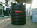
I want to make a circuit using PIC MICRO CONTROLLER which fills my tank automatically..

As my tank becomes full it should turn off the motor pump
-------------------------------------------------------
As my tank becomes low it should then turn on the motor
---------------------------------------------------------
But before filling the tank it should first check the existing of water by another sensor...
As this sensor becomes wet then we can understand that water is getting inside the tank..
and then it can continue to fill the tank....but the time will be only 5 minutes .It will have to check the existing of water between 5 minutes.If the water doesn't comes in 5 minutes then it will turn off the motor pump and restart after 1 hour and the process repeats....
----------------------------------------------------------------------------------------------------

SO in short we require three sensor ie : LOW , FULL AND WATER Sensors and a picaxe to control it as required...
Note : It is necessary that the sensors are corrosion free..

So we require total following circuits to accomplish this project :

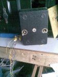
1) Three corrosion free sensors to sense the the level of water.
2) A PICAXE Micro-Controller to control the motor pump according to the sensed water level.
3) A Program code which will need to program this PICAXE Micro-controller..

------------------------------------------------------------------------------>>>>>>>>>>>>>>>>>>>

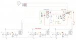
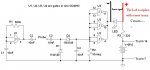
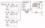
Well , I have got a circuit diagram which is little bit related to this project :
The link is :
http://www.picaxeforum.co.uk/showthread.php?12266-08M-Christmas-tree-watering-controller&highlight=christmas


=========================================================================

I hope we will have to do some modifications in Christmas-tree-watering-controller circuit and code and that's all !! :)

waiting for reply :
Mike :)
 
Last edited:

Mike.

Member
Yaa ... eclectic.... ?

I had looked this thread also but I didn't get any idea.... I hope that this thread has been banned or closed as the reason the users have posted that yusuf.businessmen has told the lie...
-------------------------------------------------------
by the way friend.... so from where to start....
 

hippy

Technical Support
Staff member
so from where to start....
Perhaps by detailing exactly what help you need, what you already have developed so far ( if anything ), and listing what programming and electronics skills you ( or others working with you ) have.
 

Mike.

Member
Hippy I have successfully created this 2 month back with 5 to 6 nan-gates IC's and it was perfectly working but the problem was that it was very bulky.. so I though to compact it's size PICAXE is better one...

I have good knowledge of electronics and little bit knowledge of PIXAXE but I hope I will create it...

and I have programming skills in c , c++ , vb.net and web designing ....

anything else you want to ask ? :)
 

hippy

Technical Support
Staff member
Hippy I have successfully created this 2 month back with 5 to 6 nan-gates IC's and it was perfectly working but the problem was that it was very bulky..
That's great and it sounds like an excellent reason to move to a PICAXE. As you already have a working solution it would make sense to post the circuit you have, show how the sensors and motors are interfaced, and it should be a simple task to provide a PICAXE program to control them. All you need is a PICAXE to replace your logic gates and it's a drop-in replacement - you've already done half the work.
 

Mike.

Member
OK....

I have attach my complete circuit diagram in my attachment which I had made 2 month back...
An the sensors are corrosion free because I have tested 2 month and it worked corrosion free....

Kindly zoom the image for better vision...

So now I want to transfer this to PICAXE...

thanks in advance...
:)
 

Attachments

RustyH

Senior Member
You best sensor for this is a IR liquid level sensor, that is solid state and will link very easily in to your circuit. I know cause I sell them :)

Not sure if you can source these locally to you though
 

lewisg

Senior Member
Some thoughts:

** There are lots of ways to sense water levels. Since you say corrosion free then that fairly well eliminates electrical contact with the water. The cheapest and quite reliable are float switches installed through the side of the tank. Another method is to tee off the bottom bung and install a sight tube with optical or magnetic modules to detect level. Then there are ultrasonic and IR rangefinders that will give the distance from their mount at the top of the tank to the water level. For deeper tanks barometric is the way to go but changes in the weather make that method difficult under 10M. However that is the way most top load washing machines quit filling. With your tank I'd go with the float switches.

** As I read your original post is seems to me you need two level sensors in the tank and possibly one sensor to detect the presence of water at the intake of the pump. The reason I say possibly is that if the pump can run dry without damage and power consumption isn't a big problem why not just turn the pump on when the low switch triggers? If the low switch does not indicate water in a minute then turn off the pump and wait an hour. If the low switch indicates water run the pump for 5 minutes or until the high water switch triggers. If the pump can fill the tank in less that 5 minutes you are done. Easy?


Some Qs:

So how long does it take for the pump to fill the tank if water is available at the pump intake?

What kind of pump?

What is the source of the water?


I like the photo of your device with the voided stickers. That is a GREAT way to start a project!
 

RustyH

Senior Member
Would IR level sensors not be the best solution here, you can get them for under $10, there are solid state (no moving parts), you can power them with the same 5v feed to your pic and the signal will hook up directly to the pic input, and they are resistant to Petrol, etc if needed (dependant on material)
 

lewisg

Senior Member
All the IR rangefinders I see under $20 max out at 1.5M. The photo of the tank looks deeper than that. I tend to discount the first and last 10% of any measuring device. Possibly you could post a link? I'd love to try one sometime.

Not having used either ultrasonic or IR rangefinders I can't say if or which would be the best choice for this application. Float switches I know. However having feedback as to the tank level could solve the problem of extended dry running of a pump from an intermittent water supply. Simply check in the program loop and if the water isn't coming up at the expected rate simply stop the pump and wait.

Having searched through previous posts on this application description makes me wonder if this is a yearly exercise. The existence of schematics and photos contributes to realism however unless this set of specifications is a common real world problem on the sub continent it does seem odd. In any case it is an excellent application for a PICAXE, once you have your sensors and output hooked up and tested if it doesn't work the way you like simply reprogram the chip! Much easier than rewiring a bunch of discrete components.
 

Mike.

Member
Some thoughts:

Some Qs:

So how long does it take for the pump to fill the tank if water is available at the pump intake?

What kind of pump?

What is the source of the water?


I like the photo of your device with the voided stickers. That is a GREAT way to start a project!
It takes 1 hour to fill the tank if water is available.....
It is normal home water pump....
It's the Municipality (Government water supply) water...

And Friend I don't want to use float switch and all that... I want to sense water level with water sensor circuit... As you can see in my circuit diagram
that I have added water sensor and that one is corrosion free because I have used 2 month regularly.

SO I want to use the concept of my water sensor to implement with PICAXE...

thanks :)

By the way thanks for replying...
 
Last edited:

cravenhaven

Senior Member
I'm a bit confused about the circuit around C3 & C4. As I understand you have shown the output of IC1(B,C,D) connected to earth, then through a capacitor to the input of an inverter.

Can you clarify what that earth is connected to?. Is it a shielded cable?.
 
Last edited:

Mike.

Member
I'm a bit confused about the circuit around C3 & C4.

Can you clarify what that earth is connected to?. Is it a shielded cable?.
The earth is connected to negative terminal of power supply..
And C3 & C4 is for only filtering..
 
Last edited:

cravenhaven

Senior Member
In your cct diagram you have labelled the IC's in the sensor part of the circuit as IC1. In each of those IC's there are 4 NAND gates, 1 is used as an oscillator and the other 3 are paralleled as output buffers. the output of those buffers (IC1B,IC1C,IC1D) are then shown as connected to an earth point. In the right most input circuit it is near the label "TY".
 

Mike.

Member
IC1 (BCD) are used to boost the sensor current (LED glows in this revised circuit diagram) so that the control circuit and timer circuit can sense signal properly..

I have only replace the led with two separate wires ( negative and positive) so that the control and timer circuit can get sense signal properly....

I am revised this circuit and I have add led for better understanding ......

As the probe gets wet the led glows..
And in my circuit diagram which I have post previously , as the probe gets wet the high signal is send to control and timer circuit...
 

Attachments

Last edited:

RustyH

Senior Member
All the IR rangefinders I see under $20 max out at 1.5M. The photo of the tank looks deeper than that. I tend to discount the first and last 10% of any measuring device. Possibly you could post a link? I'd love to try one sometime.

Not having used either ultrasonic or IR rangefinders I can't say if or which would be the best choice for this application. Float switches I know. However having feedback as to the tank level could solve the problem of extended dry running of a pump from an intermittent water supply. Simply check in the program loop and if the water isn't coming up at the expected rate simply stop the pump and wait.

Having searched through previous posts on this application description makes me wonder if this is a yearly exercise. The existence of schematics and photos contributes to realism however unless this set of specifications is a common real world problem on the sub continent it does seem odd. In any case it is an excellent application for a PICAXE, once you have your sensors and output hooked up and tested if it doesn't work the way you like simply reprogram the chip! Much easier than rewiring a bunch of discrete components.
I believe you are looking at beam break IR sensors, the ones Im talking about do not relay on a range, etc
See - http://www.sstsensing.com/downloads.aspx?file=Documents/AN0041_1_OpticalLLSensor(8).pdf

You simply mount it at the level you want the water at, as soon as the water reaches that level, a signal of 5v (or what ever you choose) is sent down the signal line to your pic. Simples
 

Mike.

Member
Thanks RustyH .... but I dont want to use any float switch or any kind of optical liquid level sensor... I want to use ac capacitor coupling circuit as a sensor because it is corrosion free..
please re-read my requirement at post #1...

And also have a look on the link :
http://www.picaxeforum.co.uk/showthread.php?12266-08M-Christmas-tree-watering-controller&highlight=christmas

and also this :
http://www.picaxeforum.co.uk/showthread.php?19555-Automated-tank-filler-using-PICAXE-08M-help...&highlight=water+tank+circuit

:)
 
Last edited:

KMoffett

Senior Member
So what is it that you are requesting Mike? You'll need a PICAXE with one more input to use my circuit (Christmas tree stand watering) to implement yours concept. It would only take small changes to the program to support three inputs and a timing loop.

Ken
 

Mike.

Member
Ok.. Ken

What are the changes will I have to do in circuit diagram.
Can you modify your circuit diagram and send me the complete circuit.


:)
 

lewisg

Senior Member
You simply mount it at the level you want the water at, as soon as the water reaches that level, a signal of 5v (or what ever you choose) is sent down the signal line to your pic.
Very nice! Better than a float. I haven't seen any of those around $10 though...

For IR range finding I was looking at these. Good for short distances but likely beyond the range for this application. Ultrasonic looks better. For around $100 you can get a IP67 exposure rated rangefinder that will give 1cm resolution over 25cm to 765cm range. Using a rangefinder like this could make a very simple system. PICAXE08M2, rangefinder, SSR and you are just about done except for the code. Nothing touches water! As previously mentioned with proper programming you could even tell if the pump was moving water. Add in a counter variable for failure to move water and you could have a alert LED or signal another device.

Since the OP insists on the impossible (no corrosion using electrified metals in municipal water :) ) the only reason to keep this thread going is to stretch our brains.
 

RustyH

Senior Member
Hi Lewis,

Yeah mate, you can pick these up for a little over $10. A brilliant little device that works in most fluids
 

hippy

Technical Support
Staff member
What are the changes will I have to do in circuit diagram.
As your circuit already works it should equally work with a PICAXE, as below -

NEW-1.jpg

Then run the following test program to check the sensors are working ...

Code:
#Picaxe 14M2
#Terminal 4800
PwmOut C.0, ?, ?
Do
  SerTxd( "B.1=", #pinB.1, 9, "B.2=", #pinB.2, 9, "B.3=", #pinB.3, CR,LF )
  Pause 1000
Loop
If that doesn't give reliable readings then READADC on the appropriate pins may give better results but best to prototype and try the easy solution first.
 

KMoffett

Senior Member
Put a high value resistor on the output side of C1 and common...100K to 1M.
Also, you want to keep the PWM frequency rather low if the drive and detector wires are in a single cable. At high frequencies you can get capacitive coupling.
Ken
 
Last edited:

Mike.

Member
ok ken....

but where is the circuit........

I want to use your Christmas tree watering circuit..........

so please modify it.

and give me the complete circuit.......
 

KMoffett

Senior Member
Mike,
Did you miss hippy's circuit and program....Post #32. The component values in my circuit are a little different and I will vouch for them...but hippy's is it.
Ken
 

Paix

Senior Member
Put a high value resistor on the output side of C1 and common...100K to 1M.
Also, you want to keep the PWM frequency rather low if the drive and detector wires are in a single cable. At high frequencies you can get capacitive coupling.
Ken
That's actually C2 in Hippy's diagram.

Go for it Mike and report back, when you have something built. :) ( Don't you just love the power of the comma? )
 
Top