Strange 7-segment LED issue
- Thread starter KandH
- Start date
Chavaquiah
Senior Member
Sparkfun does sell the part they advertise... or at least one UK redistributor I bought from does (hint: it's black, like in their pictures, not gray). So, this must have been one mistake on their part, and one that might have (or will) cost you.
Had you wired the display the "right" way around, you could have damaged it. Even undamaged, it still doesn't correspond to what you need, so I think asking SF for the right one is the best thing to do.
For a CC display, you could use a UDN298x instead of a ULN280x, but you shouldn't have to.
Had you wired the display the "right" way around, you could have damaged it. Even undamaged, it still doesn't correspond to what you need, so I think asking SF for the right one is the best thing to do.
For a CC display, you could use a UDN298x instead of a ULN280x, but you shouldn't have to.
I'm interested in knowing of this UK based re-distributor because at the moment I end up ordering direct from Sparkfun?Sparkfun does sell the part they advertise... or at least one UK redistributor I bought from does (hint: it's black, like in their pictures, not gray).
Many Thanks,
Morrolan
the 2803 should work with a common cathode display
was looking last night at data sheet descibed as a npn darlighton driver
but unfortunatey wont be any good for me that is my common annode seqments require pnp switching
did you get the display working with code in post 20
if bright enough you may as well leave as is if you want lol
just wondered if it displayed correct or was ghosting
really they should send one out for free if they gave you the wrong part keep both lol
Last edited:
Chavaquiah
Senior Member
(Sorry for the off-topic)I'm interested in knowing of this UK based re-distributor because at the moment I end up ordering direct from Sparkfun?
On SF's site, please see the link (menu on top) for the Distributors list. This item, in particular, I bought from SK Pang (link on SF's site).
How would I use a 2803 or 2003A to source current for the anode segments?the 2803 should work with a common cathode display
was looking last night at data sheet descibed as a npn darlighton driver
do u mean the anodes on your common cathode seqments (2803 wont work you need pnp switching)
was thnking driving the common cathodes with them actually d1 d2 d3 d4 mine are (20ma from memory)
depends on your needs i guess if u need the diplay brighter if you dont
you can add resistors from picaxe to seqments a b c d e f g d.p. is what i was thnking (12ma from memory)
sorry was thnking about my blue setup different colours will be different
bit hard to suggest yours is driven oppositely and a diffrnt colour lol and ive never used com cath
it may be easier to light one segment up steady 8.
measure current on d1 and a b c d e f g d.p segments
make sure it is a bit brighter than what you want
work out what values you need from there
cause remeber when actually multplexing it wont be as bright when switching
hmm just thnking too because your driving through two ports ie b and c
your probaly loosing .3 .4 across each 1 so the voltdrop will be about .8 only guessing
(this proberly needs explain when pins using less curent ie 1ma little voltdrop L= 0.01 H=5.0
sya we load up two pins 200 ohm between say c.1 and b.1guessing again lol L=0.4 H=4.6 (loss0.8v)15ma
probery the same as 300 ohms from b.1 to GND 15ma H=4.6 but gND is 0v
so if you add any transistors etc you will hav more drive current will increase ie less voltdrop
so it would be best to start with resistors in circuit first and r&d from there
hope i havnt made this worse lol
Last edited:
depends if you need too ultimately you will need to drive them with something if u need alot more current but just by putting in a transistor we are not getting as much vdrop
from our ports
i think youll be able to get it bright enuff
just by adding the transistors you will see a big difference
from our ports
i think youll be able to get it bright enuff
just by adding the transistors you will see a big difference
Last edited:
just got home sorry had to go half way thru post.
hope you hav it blown anythng
it would be good if you had some display details
otherwise this could be bad advice
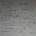
i'll see if i can draw a ruff circuit for you
after thinkin about it i thnk you need to try a less risky approach
because the display voltage may be a lot differnt than mine
i thnk you said you had 2n3392 npn transistors
see circuit attached use at least a 250 ohm resistor to start with
just drive 1 display leave c0 c1 c2 disconnected
get a full display 8 working as in post 20
check current on pin b6 if say 5ma
add c3 and so on (checking each time you dont exceed pins limits)
really need to get the multiplexin going before reducing value of resistor
and keeping all pins within safe limits
didn t really realise it would be so hard to do this way
the picaxe is quite robust
but the segment displays are easily damaged.
hopefully youll see 89oC
i would even leave higher value resistors in until u finished a project.
but once this is working it will give you an idea of how bright the display can be
and go from there
hope you hav it blown anythng
it would be good if you had some display details
otherwise this could be bad advice
i'll see if i can draw a ruff circuit for you
after thinkin about it i thnk you need to try a less risky approach
because the display voltage may be a lot differnt than mine
i thnk you said you had 2n3392 npn transistors
see circuit attached use at least a 250 ohm resistor to start with
just drive 1 display leave c0 c1 c2 disconnected
get a full display 8 working as in post 20
check current on pin b6 if say 5ma
add c3 and so on (checking each time you dont exceed pins limits)
really need to get the multiplexin going before reducing value of resistor
and keeping all pins within safe limits
didn t really realise it would be so hard to do this way
the picaxe is quite robust
but the segment displays are easily damaged.
hopefully youll see 89oC
i would even leave higher value resistors in until u finished a project.
but once this is working it will give you an idea of how bright the display can be
and go from there
Attachments
-
 209.9 KB Views: 16
Last edited:
things to consider
Things to consider and know.
The only reason i posted my circuit blue display common annode
-toataly safe to use under all conditions (no risk of damage to picaxe or blue seqments).
benifits
-code is designed to used with these
-they have the highest voltage 3.2v
-they are extremely bright low current
-i believe the ports will sink more than they will source
-when programming there is activity on all pins display lights up no need to disconnect
-they will survive bad coding
-so it makes a good designing platform for some one starting(like me )
- blue is cool lol
blue segment i use Common annode SM6105 3-3.2v 15-20ma (asia engineer ebay)
when using other displays all these characteristics can change
so there will be risk.Hardware will require R&D
may even be a good idea to start with the 20x2 if you hav 1
Sorry I 'm not more help lol
Last edited:
Ideas about components but have not tried
Dont usually like posting stuff i havnt tried myself dont even have the hardware yet lol
only had four transistors bc557 so i used those i have more blue segments lol
I believe you should be able to get any any display to work and just drive the common annodes or common cathodes from pnp or npn switching.
switching i want to try because i believe it to be a good choice transistors
pnp 2n3904 200ma 100hfe 0.2Vcesat
npn 2n3906 200ma 100hfe 0.2Vcesat
later on i might try these ic's
these operate as inverters hi in / low out
uln2803a npn darlington driver usually used with picaxe higher current relay driver
uln2003a npn darlington driver usually used for driving leds
these operate as inverters low in / high out
udn2580a pnp darlington driver usually used for driving leds 120ma 25v i believe
udn2585a pnp darlington driver higher current relay driver
other stuff / with slight change to code 6 segment driving seems to work with 16mhz easily
have not tried hardware tho.if i get a chance might try and source a cathode segment for comparison and see how it responds.i have not seen much of any elses code hardware setup so cannot comment i dont seem to find anythng when i hav a look searching
(dont seem to be any good at that yet lol, hope yourve had more success,i just look quickly at the active posts for ideas)
plan/still havent settled on hardware 20x2 seems good sofar was trying to come up witha common setup i hate pushbuttons so will just use one in projects i thnk this simplies using it lol with 3 digits i did a retic controller which ill redo code and add in memory for timers which can be changed without reprogramming
-4digit what to build on code at the moment clock,stopwatch,temperatue,counter,delaytimer,countdownUptimer,want to give them output function ie temperature(add in thermostat control u enter with 1 button control output)
may add own rtc function with out using ds1307(hippy good idea)
-already seeing 6digit may be handy for display so will be next jump and add date features.
-may change th way i control this i think can all be done from one port (b) just use more eeprom this wiil free up c port lol unfortunately hav 2 dif hardware ideas lol
-lots of thngs can be done differently with multplexin i thnk i can control 49 leds sinking from the b port this would make a interesting spectrum disply
-one idea i have controlling 30+30 leds from c + from b ports to be used with ie seconds on a clock or 360 dgrees for a compass wind direction etc
just a few ideas i have so many more lol like simple switch replace with a phototransistor
(use as touch switch)
- i need to learn more about interaction between chips as ive always tried to doit all with a 20x2 so hser hspi hi2c lcd radiocontrol x10 is way down the list of learning at the moment.
- i do tend to get distracted and do other thngs so hav been a bit slac with the codin lately-this is a great forum ppl are all great i thnk in future ill just post small working code
as i thnk this is probably easier for every1 to look at
- Westaus55 and Hippy have been brilliant helping me to improve on mycode
i believe the 20x2 can do anythng just got to find out how lol
As Sparkfun shipped me a common-cathode display instead of a common-anode, I cannot use a darlington array.
As a ULN2803A Darlington array is a common-emitter, it is useless for my application without ordering another LED display.
Is there such as thing as an open/common collector array of transistors (8 or more of - does not have to be Darlington) which can provide me with ~50mA per pin? There is so much out there that I quite often find it hard to sort the wheat from the chaff because there are just SO many variants of devices.
Can anyone recommend a common device?
Many Thanks,
Morrolan
hippy
Ex-Staff (retired)
If it's a genuine Sparkfun error it may be worth contacting them to get the part replaced as this is the simplest, cheapest and possibly quickest way to proceed. They may be prepared to ship a replacement before you've returned the wrong part.
I cannot name any high-side driver equivalent of the ULN2803A but it would be possible to build such a thing using discrete transistors though not as convenient.
I cannot name any high-side driver equivalent of the ULN2803A but it would be possible to build such a thing using discrete transistors though not as convenient.
http://uk.farnell.com/allegro-microsystems/udn2981a-t/driver-led-relay-2981-dip18/dp/1193495 ... 4,555 in stock ")
Datasheet at http://www.allegromicro.com/en/Products/Part_Numbers/2981/2981.pdf
..there's also UDN2982 but they seem a bit harder to get hold of.
Datasheet at http://www.allegromicro.com/en/Products/Part_Numbers/2981/2981.pdf
..there's also UDN2982 but they seem a bit harder to get hold of.
I have contacted them but it was quite a while ago now that I ordered it, so I'll see what reply I get.If it's a genuine Sparkfun error it may be worth contacting them to get the part replaced as this is the simplest, cheapest and possibly quickest way to proceed. They may be prepared to ship a replacement before you've returned the wrong part.
Thanks for that, I think i'll be buying a couple of them to salvage my project in it's current form (or at least it lets me make use of this LED display).http://uk.farnell.com/allegro-micros...p18/dp/1193495 ... 4,555 in stock
Datasheet at http://www.allegromicro.com/en/Produ.../2981/2981.pdf
Many THanks,
Morrolan
Bearing in mind minimum order costs from places like Farnell you might be better off on eBay looking for individual 7-segment CA displays - unless you desperately want the colon between the digits.
..or these...
http://www.rapidonline.com/1/1/1305-14-2mm-0-56in-quad-led-display.html
..or these...
http://www.rapidonline.com/1/1/1305-14-2mm-0-56in-quad-led-display.html
hi KandH,
have been looking myself pnp darlington drivers are extremely difficult to source.
you can also try using a buffer these may be hard to get too
futerlec have them so others may too
http://www.futurlec.com/Linear/TD62781AP.shtml
Td62781ap used for driving displays relays 40ma 8 channel
work a bit differently hi in / hi out
just wonder if u'd tried driving it with a transistor or 2803 on common cathode side.
trying to drive direct from port to port picaxe wont switch properly
with blue seqment i got 2ma per segment 14ma total current can hardly see
by adding transistor on the common anode and 150 ohm resistors to segments
it increased to 6ma per segment toatal current used 42ma which was good
by then upgrading to 100 ohm which i safely use now
is about 12ma per segment total currrent of circuit 82ma and is bright
hope you can get working how you want!
Hi Kandh,
i managed to source a red common cathode segment to try out.
hdsp-5303 1.6-2.0v i think the yellow 1,s are normaly 2.1-2.5v.
i had to tidy my setup a bit after seeing yours lol
i thought i,d just change the last segment and see how they compare
red common cathode driving with a 2n3904
the blue ones common anode with 2n3906
we only need to change code slightly to suit transistor base and port b what we display
suprising total current draw through the transistor is about 22ma much the same as
the blue .
Hard to make a comparrison blue are more efficinent brighter close up
but the red one can be seen more clearly from agreater distance + 2 metres
i think yellow and green will be better again viewing from distance.
http://www.youtube.com/watch?v=h-p7HlIGeRM
now that i hav 6 transistors made the jump to light speed lol 16 mhz
because of our time sharing current through the transistor has halved
6 segments a lot to look at lol.