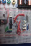
Strange 7-segment LED issue

KandH

Member
Hi all,

I have a feeling that I'm being incredibly dumb, but I am playing with multiplexing with one of these and I think I'm powering it wrong, but it's working :confused:

I understand Multiplexing and I know that others have created programs and posted schematics and code for this display but I want to learn rather than just copy someone elses code.

I've boiled down the code to a simple sequence which counts the rightmost digit from 0 through to 9 and round again on a 1 second interval. This works fine, but let me explain what is confusing me.

The display is a common anode, so for each digit I must provide a v+ on the common anode and set the cathodes in the pattern I want. As I'm only currently playing with one digit (c.3) I don't need to cycle through the other digits currently.

the b port pins are connected to the lettered cathodes of the display, and c.0 - c.3 are the common anodes from right to left (as the symbols show) with 470ohm resistors.

However, as I need to set the cathodes to the particular display pattern I require, I am using 'let pinsB = %00000110' etc.

However looking at it now, by setting each bit to 1, aren't I setting that pin high? :confused:

I know I'm using multiple IF statements here, but I wanted to boil it down to code I understood perfectly, because I had other strange things happen with select...case at 3am last night :D

Code:
#picaxe 28x2
#no_data
#no_table

let dirsB = %11111111
let pinsB = %00000000
let dirsC = %00111000

let adcsetup = 0

' symbols

symbol	digA	=	b.0
symbol	digB	=	b.1
symbol	digC	=	b.2
symbol	digD	=	b.3
symbol	digE	=	b.4
symbol	digF	=	b.5
symbol	digG	=	b.6
symbol	digColon	=	c.7
symbol	digDecimal	=	c.6

symbol	dig1Cathode	=	c.0
symbol	dig2Cathode	=	c.1
symbol	dig3Cathode	=	c.2
symbol	dig4Cathode	=	c.3

symbol	digValue	=	b0

high digColon
low digDecimal


digValue = 0

do

if digValue = 0 then
	let pinsB = %00111111
elseif digValue = 1 then 
	let pinsB = %00000110
elseif digValue = 2 then
	let pinsB = %01011011
elseif digValue = 3 then
	let pinsB = %01001111
elseif digValue = 4 then
	let pinsB = %01100110
elseif digValue = 5 then
	let pinsB = %01101101
elseif digValue = 6 then
	let pinsB = %01111101
elseif digValue = 7 then
	let pinsB = %00000111
elseif digValue = 8 then
	let pinsB = %011111111
elseif digValue = 9 then
	let pinsB = %01100111

endif

digValue = digValue + 1

if digValue  9 then
	digValue = 0
endif

pause 1000
	
loop

end
Surely as I'm actually setting the bits I want lit to 1, aren't I setting that high, when I should be setting it low as it is the cathode?

Many thanks in advance,
Morrolan
 
Last edited:

MartinM57

Moderator
...and you have the cathodes directly connected to the PICAXE pins or via a Darlington driver chip? If the former, logic low to light the LED, if the latter, then logic high to light the LED (as Darlington drivers effectively invert ... high input = switched on = output connected to GND = LED on)

EDIT: and I don't see you setting any digit cathode high - or have you wired the cathodes straight to +V (and are there any resistors anywhere? There should be)

I think a circuit diagram would help you and us...
 
Last edited:

KandH

Member
...and you have the cathodes directly connected to the PICAXE pins or via a darlington driver chip? If the former, logic low to light the LED, if the latter, then logic high to light the LED (as darlington drivers effectively invert ... high input = switched on = output connected to GND = LED on)
The cathodes are directly connected to the picaxe, no darlington driver is used. However, in the current setup (and you can verify it from my code) I am currently setting the cathodes high and it is working, when it should only work when the cathodes are low?

It is behaving as if there is a darlington chip in use when their isn't.

Many Thanks,
Morrolan
 

MartinM57

Moderator
OK - there is some confusion here if I'm understanding you

Code:
symbol	dig1Cathode	=	c.0
symbol	dig2Cathode	=	c.1
symbol	dig3Cathode	=	c.2
symbol	dig4Cathode	=	c.3
should be
Code:
symbol	dig1Anode	=	c.0
symbol	dig2Anode	=	c.1
symbol	dig3Anode	=	c.2
symbol	dig4Anode	=	c.3
..and whatever they're called, you're not setting them high (i.e powering the display)
 

KandH

Member
That's what 3am will do to you!

You're correct,
Code:
symbol	dig1Cathode	=	c.0
symbol	dig2Cathode	=	c.1
symbol	dig3Cathode	=	c.2
symbol	dig4Cathode	=	c.3
should be
Code:
symbol	dig1Anode	=	c.0
symbol	dig2Anode	=	c.1
symbol	dig3Anode	=	c.2
symbol	dig4Anode	=	c.3
OK, so 'let dirsC = %00111000' is setting the pin c.3 as an output but is not actually setting it high?

If I change it to 'let dirsC = %00111100' then the 2nd digit from the right also turns on, showing that when I set the dirsB to an output, it is actually activating that digit and powering the display?

In that case, the anodes are low when they should be high, and the cathodes are high when they should be low :confused:

Would the simplest explanation be that the device I have is common-cathode rather than common-anode?

The simple fact is it is working, but I don't understand how and I need to understand it before moving onto the next level.

Regards,
Morrolan
 
Last edited:

MartinM57

Moderator
Try some simple code
Code:
#picaxe 28x2
#no_data
#no_table

Setfreq m8

'set all relevant pins as outputs and make sure they are low
let dirsB = %11111111
let pinsB = %00000000
let dirsC = %00001111 ' note this is different - you say that the anodes are c.0...c.3
let pinsC = %00000000

'switch on digit 1 anode
let pinsC = %00000001

'cycle around digit 1 segments one at a time
do
    let pinsB = %11111110
    pause 1000
    let pinsB = %11111101
    pause 1000
    let pinsB = %11111011
    pause 1000
    let pinsB = %11110111
    pause 1000
    let pinsB = %11101111
    pause 1000
    let pinsB = %11011111
    pause 1000
    let pinsB = %10111111
    pause 1000
loop

end
What happens?
 

Chavaquiah

Senior Member
In that case, the anodes are low when they should be high, and the cathodes are high when they should be low :confused:
Perhaps you should follow MartinM57's suggestion and post a circuit diagram or even a photo.

I also use those displays and they have indeed common anodes. You're using the one you linked to, right?

If you have everything connected as you describe, I worry that you may have a bad case of reverse voltage. That should not be good...
 

MartinM57

Moderator
OK - I'm going to change the code a fraction though

Code:
#picaxe 28x2
#no_data
#no_table

Setfreq m8

'set all relevant pins as outputs and make sure they are 'off'...
'...anodes low
'...cathodes high

let dirsB = %11111111
let pinsB = %11111111
let dirsC = %00001111 ' note this is different - you say that the anodes are c.0...c.3
let pinsC = %00000000

'switch on digit 1 anode
let pinsC = %00000001

'cycle around digit 1 segments one at a time
do
    let pinsB = %11111110
    pause 1000
    let pinsB = %11111101
    pause 1000
    let pinsB = %11111011
    pause 1000
    let pinsB = %11110111
    pause 1000
    let pinsB = %11101111
    pause 1000
    let pinsB = %11011111
    pause 1000
    let pinsB = %10111111
    pause 1000
loop

end
 

marks

Senior Member
its a good idea to configure your pins usually at the start of the program
which i think yourve done
let dirsb = %11111111
let dirsc = %10111111
ie configured as outputs

if using common cathode displays direct from picaxe
pinsb must be high and pinsc must be low to light the segments on
this is whats causing the confusion
all these pins are now in low state
so c0 c1 c2 c3 have turned on display 1-4
you need to turn them off ie pinsc=%11111111
OR
if using common anodes displays direct from picaxe
pinsb must be low and pinsc must be high to light the segments
in this state the opposite will happen
all segments are on
you need to turn them off ie pinsb= %11111111
ANDIF lol
driving through a 2803chip it will be different again
and as MARTIN has most importantly pointed out
add in resistors particularly at this stage of getting the hardware right first!

hope this helps lol
 
Last edited:

MartinM57

Moderator
'cept the display is (allegedly) common anode, so pinsC must be high and pinsB must be low.

I think the dirsC command, which doesn't match the (misnamed) symbols, and not setting any pinsC high are the problems. We shall see...

EDIT: ...and we haven't even got on to:
- current limiting resistors (KandH - please put some in before doing anything. If you have none and manage to get pinsC and pinsB to twiddle the right way you may well blow up the PICAXE and/or the display - 470R will do for a start)
- exceeding PICAXE overall current limits
- needing darligton drivers that will invert the logic
- getting the the anode switching order wrong, leading to ghosting of the displays etc etc ;)
 
Last edited:

KandH

Member
'cept the display is (allegedly) common anode, so pinsC must be high and pinsB must be low.

I think the dirsC command, which doesn't match the (misnamed) symbols, and not setting any pinsC high are the problems. We shall see...

EDIT: ...and we haven't even got on to:
- current limiting resistors (KandH - please put some in before doing anything. If you have none and manage to get pinsC and pinsB to twiddle the right way you may well blow up the PICAXE and/or the display - 470R will do for a start)
- exceeding PICAXE overall current limits
- needing darligton drivers that will invert the logic
- getting the the anode switching order wrong, leading to ghosting of the displays etc etc ;)
- I did mention in a previous post that I'm using 470ohm resistors on the anodes. I'm also using a clean regulated 5v source (7805) so each anode is sourcing 10mA.
- Current source drawn from the picaxe is no more than 40mA with all digits lit (470ohm resistor between each c.x pin and each anode) and sink is straight into pinsB but again does not exceed sink limits, either per pin or total.
- I don't need to invert the logic - I was experimenting with getting to know the display first and I think I most probably have a case of reverse voltage.
- I do have slight ghosting of the displays when I use more than one digit and switch between them, but as mentioned previously I'm currently only using 1 digit so I'm not actually switching the anodes at this time.

Many thanks,
Morrolan
 

MartinM57

Moderator
I did mention in a previous post that I'm using 470ohm resistors on the anodes.
Sorry I missed that
Current source drawn from the picaxe is no more than 40mA with all digits lit (470ohm resistor between each c.x pin and each anode) and sink is straight into pinsB but again does not exceed sink limits, either per pin or total.
But you'll probably find that with homemade multiplexing you will have to reduce the 470R to get decent brightness - but that will exceed the PICAXE or pin specs. You'll probably get away with it as it is only for a short duration (but you're still exceeding the specs), but if your multiplexing stops (for some reason) with segments lit, something might let the smoke out. The only proper way is a Darligton driver ... but you know best what risks you are happy to take. I can send you some displays with one segment broken if you want :D

- I do have slight ghosting of the displays when I use more than one digit and switch between them, but as mentioned previously I'm currently only using 1 digit so I'm not actually switching the anodes at this time.
Just make sure you switch the current display completely off (anode and cathodes) before switching on the new one - use multiple pinsX commands.
 

marks

Senior Member
i did actually try before with blue segments 3.2v
driving direct the current was too low
i actually had to put resistors in use transistors
to get the display brighter

so this will be different for diffent colours
 

marks

Senior Member
Try this should work if your using common anodes
hope your using 20x2 lol
Code:
let dirsb = %11111111                                        '  make portb all outputs)
let dirsc = %00111111
pinsb=255

temp:

Dig1:   let pinsb = 249 : high c.3 : pause 1 : low c.3       'Display1       1
                                          
Dig2:   let pinsb = 144 : high c.2 : pause 1 : low c.2       'Display2       9
			
Dig3:   let pinsb = 156 : high c.1 : pause 1 : low c.1       'Display3       o

Dig4:   let pinsb = 198 : high c.0 : pause 1 : low c.0       'Display4       C

goto temp
  
'       Common anode
'      program must loop and always be continuous with out pausing

'     pinsb =(value determines whats displayed   255  Clear display    (   )
'                                                  0  full display     ( 8.)
'                                                249  will display     ( 1 )
'        high c.3   ( turn on  )
'        pause 1   ( on period)
'        low c.3   ( turn off)

      '                    a
	'                  -- --  
	' B0-A  ( 1 )     |     | 
	' B1-B  ( 2 )    f       b
	' B2-C  ( 4 )     |  g  | 
	' B3-D  ( 8 )      -- --   
	' B4-E  ( 16)     |     | 
	' B5-F  ( 32)    e       c
	' B6-G  ( 64)     |  d  | 
	' B7-dp (128)      -- --  o 
	
	' adding all the numbers up turns of all segments
	' if we want to display a  (C)   we turn off segments (  b   c   g    dp )   add values
      '                                            example  (  2 + 4 + 64 + 128)  = 198
 

KandH

Member
i did actually try before with blue segments 3.2v
driving direct the current was too low
i actually had to put resistors in use transistors
to get the display brighter

so this will be different for diffent colours
I don't doubt that I will have to change to a transistor/darlington driver setup (I have plenty of both) when I attempt the full multiplexing setup, but I tend to get the very basics going and build up - 1 segment lit, same segment in all 4 digits lit, a number, a cycle through all numbers on one digit etc. and that's where I'm upto so far!

Marks - I have some of your work bookmarked, because I am essentially duplicating one of your projects although I started before I realised you'd already done it. :D

I'm building a clock with DS1307 and a DS18B20 but I wasn't intending to add a user-configurable time/date, just set it via MacAXEpad (such a shame there is no simulator in it :() but now that I see you have, I might add a user-configurable time/date once I've finished getting it to display the time and the temperature! I think a reverse-voltage situation also explains why the decimal numbers that you use in your lookup commands don't match what I have (although I prefer binary or hex - something that was discussed at length in your thread!) - out of curiosity what was your reasoning for using EEPROM and LOOKUP for storing your digit information?

I have some 2N392 transistors but I cannot for the life of me find a decent datasheet for them so I am wary of using them in anything, but if anyone can let me know the specs of these I would be eternally grateful.


Many Thanks,
KandH (Morrolan)
 

marks

Senior Member
2n3392 500ma npn

are you using a common cathode display then
if you are u can convert my codes just take 255
eeprom 0,(192,249,164,176,153,146,130,248,128,144,255) 'Display (0,1,2,3,4,5,6,7,8,9,blank) common anode
eeprom 0,(63,6,91,79,102,109,125,7,127,111,0) 'Display (0,1,2,3,4,5,6,7,8,9,blank)
D.P BECOMES + 128
common cathode

for 3 digits i actually used branching with success lol
lookup tables are only fast enough for simpler code

eeprom makes it faster easily display 4 digits with a clock
wanted code as efficient as i could get it without having to in crease speed
Code:
let dirsb = %11111111                                        '  make portb all outputs)
let dirsc = %00111111


temp:

Dig1:   let pinsb = 255   : low c.3 : pause 1 : high c.3       'Display1       8                                          
Dig2:   let pinsb = 111 : low c.2 : pause 1 : high c.2       'Display2       9
			
Dig3:   let pinsb = 99  : low c.1 : pause 1 : high c.1       'Display3       o

Dig4:   let pinsb = 57  : low c.0 : pause 1 : high c.0       'Display4       C


goto temp


'       Common cathode
'      program must loop and always be continuous with out pausing

'     pinsb =(value determines whats displayed   0      Clear display    (   )
'                                                  255  full display     ( 8.)
'                                                    6  will display     ( 1 )

'        low c.3   ( turn on)      
'        pause 1   ( on period)
'       highc.3   ( turn off )       

        '                    a
	'                  -- --  
	' B0-A  ( 1 )     |     | 
	' B1-B  ( 2 )    f       b
	' B2-C  ( 4 )     |  g  | 
	' B3-D  ( 8 )      -- --   
	' B4-E  ( 16)     |     | 
	' B5-F  ( 32)    e       c
	' B6-G  ( 64)     |  d  | 
	' B7-dp (128)      -- --  o 
	
	' adding all the numbers up turns on all segments
	' if we want to display a  (C)   we turn on segments ( a  f  e  d   )   add values
      '                                            example  (  1 + 32 + 16 + 8)  = 57
6 digits is easy to achieve with a bump up to 16mhz
proberly addthe date features too and display seconds too lol
hav been distracted lately lol and use a 2083 instead but havnt got 1 yet
anything else on that list lol i do ask for suggestions lol
 

Attachments

Last edited:

KandH

Member
2n3392 500ma npn

are you using a common cathode display then
if you are u can convert my codes just take 255

lookup tables are only fast enough for simpler code

eeprom makes it faster easily display 4 digits with a clock
wanted code as efficient as i could get it without having to in crease speed

6 digits is easy to achieve with a bump up to 16mhz
I'm still running at 4mhz as I haven't touched the clock frequency yet, but I'm only using the internal resonator because I don't have an external.

I've got no problem calculating my own codes from the binary but I didn't know that EEPROM and lookups were faster than select / case statements.

Once I get my reverse-voltage issue fixed tonight I might move to a lookup instead of loads of select/case statements - it certainly seems much more efficient for storing character patterns.

Cheers,
Morrolan
 

marks

Senior Member
YOU PROBERLY WILL NEED 8MZ TO DO A CLOCK
i up dated post 20 with some info
i do things different lol
i did a simple temperature program u should try it
what chip r u using
 

marks

Senior Member
i,m jealous now lol i wish i had 1 to try
it will do 8 mhz internal good enough for 4 digit clock
interesting the 3v version does 16 mhz internal

i never thought i,d get the 20x2 to work with ds1307 and ds18b20
but it works ok with a few tricks lol
i have a few more ideads yet 20x2 not dead yet lol
i can try covert temp program if you want to try
idont hav 28x2 (wishlist)or can even test the common cathode driving ud hav to
r&Dit lol celsius or f
 

KandH

Member
i,m jealous now lol i wish i had 1 to try
it will do 8 mhz internal good enough for 4 digit clock
interesting the 3v version does 16 mhz internal

i never thought i,d get the 20x2 to work with ds1307 and ds18b20
but it works ok with a few tricks lol
i have a few more ideads yet 20x2 not dead yet lol
i can try covert temp program if you want to try
idont hav 28x2 (wishlist)or can even test the common cathode driving ud hav to
r&Dit lol celsius or f
I have a working temperature program but it doesn't do decimals yet, only whole degrees so I'm going to try and delve into readtemp12 as well with this.

What limitations did you find with the 20x2? The only one I came across was pins - you could do a clock at 64Mhz and totally eliminate any flicker!

Celsius as I'm in the UK and we like metric here for temperature.
 
Last edited:

marks

Senior Member
none really
had trouble with hi2c using same b pins as the seqments but got that working
was nearly going to move it all to c pins lol
biggest trouble with muliplexin reading hi2c or readtemp or owin
the time doing the reading will blank the display readtemp will loose it for 750ms
which is a lot
using hi2c and owin for temp not too bad and the way i doit you dont notice at all if u change whats showing on the display
read owin every minute (change to temp)
readhi2c updatetime (change back to time)

going to 6displays you do notice the flicker
but uping frequency to 16m and its sweet better than four lol

i would hav loved to try the clockin on the 28x2 and use an external crystal to see how acurate time could be
the 20x2 drifts abit it can be as bad a 1 sec hour so after 12hrs it can be 12 secs out over night it drifts back
it can be spot on again in the mornning i bit annoy so a ds1307 is really need a faster1 would be better tho.

will post my temp prgram when i get time updates evry 6 sec u just see it flick hardly noticable
have put ds18b20 example code in the snipets area hav a try.
 
Last edited:

KandH

Member
But what impact would the 20x2 have on the DS1307 if you were using an external 32Khz crystal? Surely the drift would be from the DS1307 and not the 20x2?
 

marks

Senior Member
was trying to do aclock without a ds1307

withit it updates every minute no problem

try this temp prog no guarentee not tested lol
 

Attachments

Last edited:

KandH

Member
Code:
#picaxe 28x2
#no_data
#no_table

Setfreq m8

'set all relevant pins as outputs and make sure they are 'off'...
'...anodes low
'...cathodes high

let dirsB = %11111111
let pinsB = %11111111
let dirsC = %00001111 ' note this is different - you say that the anodes are c.0...c.3
let pinsC = %00000000

'switch on digit 1 anode
let pinsC = %00000001

'cycle around digit 1 segments one at a time
do
    let pinsB = %11111110
    pause 1000
    let pinsB = %11111101
    pause 1000
    let pinsB = %11111011
    pause 1000
    let pinsB = %11110111
    pause 1000
    let pinsB = %11101111
    pause 1000
    let pinsB = %11011111
    pause 1000
    let pinsB = %10111111
    pause 1000
loop

end
Using this code untouched, it most definately looks like my device is common-cathode as exactly the opposite of what you were expecting happened - when you were expecting '1' to be displayed, every digit but those 2 were lit.

Please see the picture below for wiring, and the video is here.

Many Thanks,
Morrolan
 

Attachments

Last edited:

marks

Senior Member
that was clever coding from martin
looks like common cathode
and your driving them direct

ive reedited post 20 try that code lol
updated bas file in 28 hopefully should work

just had a quick look default frequency is 8mhz for 28x2 internal

nice pic neat layout too
 
Last edited:

westaust55

Moderator
While the Sparkfun website for the time description does state Common Anode, the datasheet they link to shows common cathode configuration.

But Sparkfun are not alone in such errors.
Of some of the 1-Wire devices I purchased recently, 1 chip type has a family code that does not match the datasheet. Maxim has confirmed it was a special run they produced for a Customer and will work fine for me just with different family code. (was it a Mercedes truck? . . .ask no questions!)


Another 1-wire chip was to be delivered in TSOP package which I can handle. But I received in TDFN package (=Thin Dual Flat No Leads) which is so small I have to buy an electron micrcoscope to use it. (currently waiting to see what the seller is going to do about it).
Think TDFN should stand for This Device F@*#% No-go :eek:
 

KandH

Member
Less than 2 seconds on Google ... "LED 7-SEGMENT .4" 4DGT YELLOW CC - LTC-4727JS". CC = Common cathode. Problem solved. I wonder if Sparkfun know what they're shipping....

I'm sorry, that's obviously been my fault for just believing what Sparkfun tell me!

At least I can now rest in the knowledge that I didn't have a reverse-voltage.


In a common-cathode configuration, please can someone describe where I need to wire the darlington driver? I know it's not as simple as "stick it between the picaxe and the anodes" (because I've tried that) but I'm confused about exactly where to wire it?

Many Thanks in advance,
Morrolan
 

MartinM57

Moderator
While the Sparkfun website for the time description does state Common Anode, the datasheet they link to shows common cathode configuration.
?

http://www.sparkfun.com/datasheets/Components/LED/7-Segment/COM-09480-YSD-439AY2B-35.pdf definitely shows common anode (and you would think that the model number on the datasheet would match the part number on the device - which it's nothing like).

A bit of googling uncovers http://datasheet.octopart.com/LTC-4727JS-Lite-On-datasheet-79427.pdf which shows common cathode and at least a consistent part number.
 
Last edited:

MartinM57

Moderator
Wiring up a CC display properly with darligtons (i.e close to zero current being sourced/sunk by the PICAXE):
- cathodes to ground
- some sort of high side switch/PNP darlington arrays - not the ULN2xxxx you've got, but I can never remember the part number. Someome will jump in and supply it

The "normal" display is CA as it's so easy to interface to - normal low side switching.

If you did buy from SF, just tell them they've sent the wrong part, it's too low value to return and please send me what you advertise/I ordered...you'll be jumping through too many hoops with what you've got
 

MartinM57

Moderator
Good idea - as soon as I turned the correct schematic upside down I saw it! Thanks for the tip :D
'cept that's not a proper job - which is why I deleted it, but you were too quick ;)

The idea of using a darlington driver is to sink/source (virtually) no current in the PICAXE - so normally you connect the CA to +V and control the segments with the darlingtons.

With a CC and the darligtons in the cathodes, how can you power the anodes - only option is from the PICAXE, which is not the idea (unless you had some high sided switches as well, but that's getting silly now)

Think you should get the proper parts...
 
Top