You can use "Sehr geil"Wolfgang appears to have created the ultimate project feature add-on with this bd and software. Not too shabby, as we say in the States.
Simple oscilloscope for Picaxe work - finally finished! (DPScope SE)
- Thread starter womai
- Start date
Just uploaded the full hardware description of the scope. It goes through all the details of how the circuit is built and why, hopefully you'll find it readable (let me know if you don't!). You can find the file (PDF) on the DPScope SE website (www.dpscope.com --> DPScope SE --> Downloads), or simply click here:
http://www.dpscope.com/files/DPScope_SE_Design_Description.pdf
For future questions I'll assume you have read those pages first") - just kidding, constructive comments are always welcome.
- just kidding, constructive comments are always welcome.
http://www.dpscope.com/files/DPScope_SE_Design_Description.pdf
For future questions I'll assume you have read those pages first
- just kidding, constructive comments are always welcome.Worked all day yesterday at one part-time job, all last night at another, then all day long again today at the first one. I guess the job description fits; I work each job "part of the time." Heaven help me if I get a call from any of my other part-time jobs.
What I find really aggravating is that all this work is coming just when Wolfgang has delivered on the 'scope, and I'm too weary to even read the manual. Sigh.
What I find really aggravating is that all this work is coming just when Wolfgang has delivered on the 'scope, and I'm too weary to even read the manual. Sigh.
I just read the SE scope users manual and the "DPScope SE Design Description" guide. Lots of good stuff. I do appreciate all the time and effort that goes into a good explanation of how my test equipment actually works, so I can then use it to its fullest potential, and repair it if that ever becomes necessary. Usually, such thorough work only comes out of large corporations like HP (Agilent) or Tektronix. Wolfgang is a regular one man corporation. He must type a whole lot faster than I do.
Off to work.
Off to work.
>He must type a whole lot faster than I do.
... or cleverly leverage and re-use applicable portions from previous projects (PC software, user manual, and hardware descriptions for the DPScope SE owe a lot to the respective code and documents of the original DPScope) Not that big companies wouldn't do the same for their products.
... or cleverly leverage and re-use applicable portions from previous projects
(PC software, user manual, and hardware descriptions for the DPScope SE owe a lot to the respective code and documents of the original DPScope) Not that big companies wouldn't do the same for their products.
Last edited:
I figured out what I was doing wrong with my prototype SE, the reason I was reading no 2.7 or so volts offset with the inputs open.
I did the calibration with the scope's inputs floating, not grounded, so it read the offset voltage as ground. That's OK when you're fooling around with a prototype just looking at the way the scope's features work together, but it's not so good when you're trying to make actual measurements.
This time around I did the re-cal with the inputs shorted to gnd, and I set the ranges to 50 mV/div, the Averaging to 20 samples, and tweaked to ~0 V (+/-) using the DMM display. Very handy.
Well, the PWM output already gets used to generate the trigger threshold, so no luck there. And the firmware already uses both interrupts (low and high priority), so a time interrupt is not an option either. The main loop is busy serving the polled USB connection and processing commands and data. Guess I am out of luck there.
Also, I did do a few tests with a simple inverter charge pump driven that way (couple diodes and capacitor), but once you start drawing a few mA for the op-amp the supply voltage drops a lot and ripple gets pretty bad - which shows up on the waveform (the CMRR of an op-amp isn't that great at 100 kHz...). Not even mentioning the fact that I'd need to use a different op-amp (not many rail-to-rail ones that can do more than 5V and have a GBP of 10 MHz, and if they can they cost a whole lot more than the MCP6024).
I like the single supply rail solution - keeps things simple
Have assembled and set up my scope - brilliant work Wolfgang!
Just a couple of suggestions re calibration.
1:
At Step 23: Offset adjustment (part 3);
Change voltage scale to 50mV/div (as per exisitng intructions)
Change averaging to 20
Open Utilities measurements
Make adjustments using the Level/Mid reading. With averaging at 20 the numbers - for me anyway - were steady enough to see and much easier to determine when floating around zero than using the main display. However it takes longer to see the results of a change and it is easy to oveshoot the change (see the next suggestion which might help with this also).
2
The trim pots are real fiddly to use - perhaps some tweaking of the values for R13/R16/R17 could be investigated.
On the Notebook, the USB voltage levels were steady but the cooling fan generated all sorts of strange vertical and horizonal artifacts on the display once it started up and when it changed speed - no problem on the desktop PC.
Thanks again.
lbenson
Senior Member
Wolfgang,
Thanks for another fine piece of gear. I love the size of it (not to mention the capabilities). My working space seems to get more and more cramped.
The kit went together very well, and the adjustment also. I was worried that I had two blue ceramic capacitors left over, marked 24J. There was no place to put them, so I left them out.
The instructions were very good. I noticed two small text errors. On page 4, "be" is omitted in what should be "they will be destroyed". On page 26, "click on the read and the blue "x" buttons" should have "red" instead of "read".
I'd suggest one minor addition to the instructions: in Step 23: Offset Adjustment, I'd add a sentence saying that the fine adjustment is made using the same trimmer resistors as were used for the coarse adjustment.
Thanks again.
Maxim has a charge pump doubler & inverter in a single DIP-8 package (so you get roughly +/-9V - still unregulated - from a single +5V supply), but same thing here, once you draw current the high-frequency ripple increases a lot and makes it to the signals. Plus, adding a few $$ and a single-sourced component to a low-cost design is a showstopper for me.
@BCJKiwi: Yeah, the offset adjustment guide was written before I implemented the DMM display; will change the documentation as suggested. For the trim pots, will see what I can do with regards to the resistor values. I don't want to make it too tight; the options are (1) increasing the fixed resistor values - but that makes the offset voltage less stiff, (2) reducing the trimmer value (but it's already 100 Ohms, lower than that becomes hard to find), or (3) use a 10-turn trimmer (but that adds around $3 to the cost and I'd need to change the PCB layout).
Noise on USB - my experience is that laptops tend to be much worse than desktop PCs; one option is to run the scope on a self-powered USB hub instead of directly at the laptop. Could also try to snap a ferrite choke around the USB cable. When I do another scope then I'll use a dsPIC33 that runs at 3.3V - that way I can add a low-dropout regulator to clean up and stabilize the USB supply.
Re trimmer pot;
Just a wild off the top of my head thought, untested nor carefully considered but hey, why not throw it out there!
As I only seem to use around 1/8 to 1/4 of the range of movement, would it be feasible to tighten up the tolerance on the two resistors and place a third resistor in parallel with the pot.
The tighter tolerance should guarantee the pot is working in the right place and the parallel resistor would effectively reduce the value of the pot as it would require more movement to achieve the same resistance change.
I was considering putting in a couple of 10 turn trimmers I have lying around. Of course, I was also contemplating how to get 12 MHz for the clock from my rubidium std, as well. Then I decided that those thoughts were all just foolishly gilding the lily. I'll just use the SE the way it is and was meant to be used.
However, I am swiping the probe pod leads from an old broken down HP logic state analyzer I have gathering dust, and will use them to make up a nice set of logic probe cables for the SE. (After all, it works, and those little clippy things ain't cheap.)
However, I am swiping the probe pod leads from an old broken down HP logic state analyzer I have gathering dust, and will use them to make up a nice set of logic probe cables for the SE. (After all, it works, and those little clippy things ain't cheap.)
cachomachine
Senior Member
Hi everybody
I found that on Ebay for those who would like to make a grabber cable for the logic analyser portion of the DPscope
http://www.ebay.com/itm/60-Grabber-Test-Probe-Single-Hook-Clip-6-color-Small-/260761768166?pt=LH_DefaultDomain_0&hash=item3cb69cd0e6
Cacho
I found that on Ebay for those who would like to make a grabber cable for the logic analyser portion of the DPscope
http://www.ebay.com/itm/60-Grabber-Test-Probe-Single-Hook-Clip-6-color-Small-/260761768166?pt=LH_DefaultDomain_0&hash=item3cb69cd0e6
Cacho
hippy
Ex-Staff (retired)
That seems a reasonable deal but the cheaper lower quality clips with side-hooks can be a pain in use; won't fit between IC legs and sometimes prone to falling off component leads. They are quite wide bodied so can present problems if connected to densely packed signal pins.
Thin bodied clips with claws using ultra-flexible cable are often well worth it if prepared to pay the extra cost. Once source is http://www.saleae.com/accessories
YMMV but, like OLED versus LCD, once used it's hard to go back.
Simple Mod?
Just received the scope and had it up and running in no time - it really is an excellent piece of work.
One quick question, is there any reason I can't take the x10 connections to pins c2 and c7 which I assume are just swinging between 0 and 5V when over driven and connect them to two of the logic inputs (outside the 10k resistors) so that I can use my scope probes as logic inputs for things like i2c which is too fast for the scope mode?
Best regards
Peter
Do you mean RC2 and RC7 on the PIC chip?
If so, that looks like a reasonable thing to do. A pretty good idea, actually.
I expect there are going to be several useful modification tricks that can be done with the SE scope, simply because folks will have all the info they need in order to make it do whatever they want done. That's the beauty of a simple, dirt-cheap scope with a lot of documentation. You can easily adapt it to your purposes without much concern for damaging it. And if it does get damaged, a quick $2 fix has it up and running once again.
I shudder every time I have to pull the case off one of my HP or Tek scopes. Just too much of an investment and too many delicate circuits for me to want to go in and make any changes whatsoever.
Last edited:
That would work only as long as you make sure the signal into the PIC crosses the TTL threshold of about 0.8V. Which can be tricky to tell from the scope signals, and you could only feed in very small, attenuated signals because they will get blown up 10x. Note that there is no real offset change in this scope, the offset is a fixed 2.5V and the software simply shows you a different (7-bit wide) portion of the 8-bit-wide ADC range.One quick question, is there any reason I can't take the x10 connections to pins c2 and c7 which I assume are just swinging between 0 and 5V when over driven and connect them to two of the logic inputs (outside the 10k resistors) so that I can use my scope probes as logic inputs for things like i2c which is too fast for the scope mode?
I think it would be easier to build a BNC-to-jumper header adapter so you can attach the probes to the logic analyzer port.
I've got standard 1x 10x switchable probes. The point was to be able to just use them direct as logic inputs without having to have things connected to the back of the DPScope. The reason for using the 10x inputs to the processor was that I assumed that when a TTL level signal was applied to the normal scope input it looks like the 10x opamp stage which is permanently connected would just saturate at either VCC or GND (assuming perfect rail to rail operation of the op amp, not true but should be close enough).
Wolfgang, I asume I'm missing something as I don't understand your point about "small, attenuated signals ". My proposal is to directly connect UC1-14 to J3-2 and UC1-9 to J3-3.
Best Regards
Peter
Wolfgang, I asume I'm missing something as I don't understand your point about "small, attenuated signals ". My proposal is to directly connect UC1-14 to J3-2 and UC1-9 to J3-3.
Best Regards
Peter
The op-amps in the scope front-end are offset to 2.5 volts in order to look at AC. While the idea of using the 10X gain to drive the signal to the rails (through the protection of the input resistors on the logic inputs) makes sense, the actual "low" voltage generated by the op-amps may not go close enough to actual ground to reliably trigger a logic low on the digital inputs.
I'd suggest some experimentation is in order, as ultimately what matters is, "Does it work and not blow anything up?"
I'd suggest some experimentation is in order, as ultimately what matters is, "Does it work and not blow anything up?"
Well, the good news is, as long as you input (to the BNC jacks, not the logic analyzer header!!!) does not go beyond +/-100V you will not blow up anything. It just won't work, that's all
0V at the scope input results in 2.5V going into the PIC. To get the signal into the PIC to rail reliably at +5V and 0V, respectively, when going through the 10x paths, you'd need to put a voltage exceeding ~ +/-2V at the input. So if your logic signal is 0V/5V you'd need to shift it down to -2.5V/2.5V. Not sure this is worth the trouble.
I suggest reading through the hardware description, www.dpscope.com --> DPScope SE --> Downloads, it goes into great details with regards to the analog signal path.
lbenson
Senior Member
Re grabbers, I just found and ordered these today--8 instead of 60, for $2.27US: http://www.ebay.com/itm/F01893-1-Set-8-colors-mini-SMD-IC-Hook-Clip-Grabbers-Test-Probe-multimeter-/250917128567?pt=Radio_Control_Parts_Accessories&hash=item3a6bd38977
If you're going to use single-hook grabbers, I suggest you get a couple of "chip clips" from somewhere as well. These are spring-loaded plastic clips that clip onto DIP IC's and bring electrical contacts up to the top of the clip to ensure easy access for probes and mini-grabbers. They're a handy troubleshooting aid on any PICAXE project using DIP IC's.
I got several of them used, cheap, because they are no longer used by designers much, as most all modern design work has shifted to computer models and SMT components.
I got several of them used, cheap, because they are no longer used by designers much, as most all modern design work has shifted to computer models and SMT components.
BillyGreen1973
Senior Member
These look quite handy too.
SMD and IC legs are easily clipped with these. 12 for £2.69 and free UK postage..BARGAIN!
SMD and IC legs are easily clipped with these. 12 for £2.69 and free UK postage..BARGAIN!
greencardigan
Senior Member
Hi Wolfgang
I've got my kit all built and working. Thanks!
My past experience with scopes is virtually zero I'll be reading the xyzs of scopes doc before I blow things up.
Like others I noticed a few minor things in the assembly guide the could be changed.
1. Step 10 - the picture is upside down
2. Step 11 - the picture shows the components from step 12 already installed.
Thanks again!
greencardigan
Senior Member
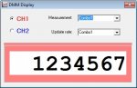
My DMM window goes like this after I open it the second time. Is that normal?
Version 1.0.2
Version 1.0.2
He was working late at night, gc, and didn't get all the pics at all the right stages and had to make do. Still, I've seldom seen better assembly instructions since Heathkit closed their doors. The fact that everyone's scope is going together and working first time, speaks for itself.
It amazes me how the guy can be a one-man-corporation in his spare time. It really does. I spent an entire day just reviewing the assembly manual for him.
I can't imagine having to spend the time it took to actually write it, take all the pictures as he built up a bd, then create a pdf of it and post it on a web site he created to disburse it, that and a parts list, and an operator's manual, and an online store, etc. That's not even including developing the prototype, designing the bd, the hardware packaging, developing the firmware, the PC GUI, ordering parts, packing kits, handling orders, etc. And all in the middle of moving to another continent. Amazing.
What's most amazing is that he's doing this all for basically nothing in the way of income, just so poor hobbyists and techies can get their hands on a dirt-cheap DSO to solve their PICAXE problems. There are some really great people in this forum. He's one of 'em.
Last edited:
It's "normal" at the moment, but it's wrong. He's aware of it and I expect will try to get it fixed in the code when he has a bit of time to get to it. He just added the DMM mode the other day at my suggestion and it still has a bug or two. Right now I just close the scope pgm and reopen it to get back a working DMM window.My DMM window goes like this after I open it the second time. Is that normal?
Version 1.0.2
View attachment 10492
There are also problems in the file saving and setup saving process, and a few other quirks still to be ironed out.
Fortunately for us, the www exists and we can just go to his site and download new GUI code whenever he updates it. The firmware in the PIC itself seems very solid as far as I can tell from beating up on my prototype for the last several weeks, so things are looking pretty good.
The hardware and firmware are done. The kits are going out to users. The feedback is getting to Wolfgang, and features are getting fixed or added as time permits. The dirt-cheap scope lives. Life is good. I just wish these and PICAX'es had been available 40 years ago. Sigh.
Last edited:
Yes, not normal, but already fixed in the latest version (not published yet).
Other known bugs (so that nobody needs to wonder):
- 1:10 probe mode not implemented yet (actually, half implemented in the unpublished version)
- save/restore setup does not include all settings
- waveform save does not include logic channels
- log to file does not include logic channels
Should all be fixed in the next real release.
Wolfgang
greencardigan
Senior Member
Whoops, I think I did this too. In fact I'm so new to scopes I didn't even know that the little alligator clip hanging off the probe was the ground connection!I figured out what I was doing wrong with my prototype SE, the reason I was reading no 2.7 or so volts offset with the inputs open.
I did the calibration with the scope's inputs floating, not grounded, so it read the offset voltage as ground. That's OK when you're fooling around with a prototype just looking at the way the scope's features work together, but it's not so good when you're trying to make actual measurements.
This time around I did the re-cal with the inputs shorted to gnd, and I set the ranges to 50 mV/div, the Averaging to 20 samples, and tweaked to ~0 V (+/-) using the DMM display. Very handy.
Maybe there should be something regarding the ground connection in "First Acquisition" section in the User Manual and in the calibration section of the Assembly Guide.
Anyway, I'm measuring -1.18V when probing a nimh cell which is 1.38V. Is that because I calibrated it wrong?
Sorry for the silly questions.
My first guess, you probed the - side with the probe tip and the + side of the battery with the ground lead? That would explain the "wrong" polarity. Also, keep in mind this is not a high-resolution multimiter but rather it is a scope with 8 bit resolution, so in the 2V/div range resolution is only around 0.2V.
greencardigan
Senior Member
I had the ground lead on the negative side. When I put the ground on the positive side I was getting approx -3.8V. I'll try re-calibrating when i get home.
greencardigan
Senior Member
It's all good now after recalibrating with the probes grounded. Three cheers for Wolfgang!
Some comments on the DPScope SE scope inputs. (Hope I have this figured right, and I'm hoping Wolfgang will correct me if I'm wrong):
The scope inputs will look like a 1 M Ohm resistor tied to + ~2.8 volts relative to the scope's ground. This won't affect an AC input's reading much, (it's just a necessary quirk in the design of an inexpensive AC input stage,) but will affect a DC reading (which, BTW, should be made in Auto trigger mode as there are no voltage transitions to trigger on.)
DC measurements (and AC signals with a DC offset,) will be affected by the input offset circuit, but any DC or AC source with an internal resistance or impedance of 10K ohms or less will read very closely to within the degree of accuracy of the scope. Only very high impedance DC sources, or AC signals riding on DC, will have their actual readings distorted by the scope's input offset, with the AC signal portion reading fairly correctly, but the DC offset value being off a bit as the 1 M Ohm coupling tends to pull the input voltage toward +2.8 volts.
I noticed too that the DMM mode will read a DC voltage that would be off the the scope screen a bit, but at some point the DMM displayed voltage value will "freeze" as the A to D reaches either 0 or 256, and the V/div range selector must then be adjusted accordingly.
As the SE scope would reasonably be expected to work as an addition to a test tool kit that starts with a good DMM, it's small quirks when functioning as a DC Volt meter are of no real consequence, and it's nice to know that its scope mode can, in fact, do some convenient DC voltage measurements as well as its intended AC signal work.
That's good news for PICAXE experimenters, who, I know from experience, are forever attempting to look at multiple signals at the same time, often with a bare minimum of test gear.
Last edited:
Some comment to this: Yes, input looks like 1 MOhm to ~2.8V. On a "normal" scope the input is 1 MOhm to ground (0V). BUT both scopes will affect the measured signal if the signal source has very high impedance, and it will affect both AC and DC component (DC onless the DC level is identical to the termination voltage, 2.8V or 0V, respectively).
Assume 5V input from a 1 MOhm source:
"Normal" scope:
voltage divider, ratio 1:2, 1 MOhm + 1 MOhm going to 0V, hence measured voltage
0V + (1M / (1M + 1M)) * (5V - 0V) = 2.5V,
so the normal scope affects the reading as well.
DPScope SE:
voltage divider, ratio 1:2, 1 MOhm + 1 MOhm going to 2.8V, hence measured voltage
2.8V + (1M / (1M + 1M)) * (5V - 2.8V) = 3.9V,
None of the two scopes will show the source's unloaded voltage of 5V, because the scope loads the source's output significantly.
The confusing thing is only if the scope input is not connected to anything. Most people implicitly assume "unconnected means 0V", whereas in fact the input voltage is completely undefined. For an infinite input impedance even the smallest static charge could result in many kilovolts! (just think of one of those historical electrometers who can show a huge voltage after being touched by some charged object, but then not connected to anything). A typical scope with the bottom of the divider connected to GND will drift to 0V, the DPScope with the bottom at 2.8V will drift to 2.8V.