No, this behavior is actually normal. The scope input divider does not go to ground but to approx. 2.8V (once it is adjusted), because center is at VCC/2=2.5V. That way the scope can live with just a single supply rail (5V) and does not need a negative supply (would have made the design more complicated and more expensive). If you short the input then the bottom end of the input divider sits at ~2.8V, the other (top) end sits at 0V, and the output to the op-amp works out to 2.5V due to the resistor values (900k and 100k) used, which the software recognizes as zero. But if you leave the output floating the op-amp input will go to wherever the bottom of the divider sits, i.e. ~2.8V, which is 0.3V higher; since the divider is 1:10 the scope (which does not "know" there is nothing attached) now says the input apparently sits at 10x(2.8-2.5)= approx.3V which is exactly what you see.
Simple oscilloscope for Picaxe work - finally finished! (DPScope SE)
- Thread starter womai
- Start date
Thanks Womai In that case works straight off the soldering Iron ;-)
Oh apart from the PCB needing trimming the other, small, issue with the assembly manual is it doesn't mention the 2 values of ceramic capacitor included, as mentioned in the other thread ( 22pF and 24pF for C12 & C14 if i remember correctly ) and the parts list states 5 100nF ceramic caps for C3 C4 C9 C10, 5 pieces were included in the kit not sure why there is a spare one included.
Do I get a prize for first to complete :-J
Thanks for all the feedback, will help me in improving the documentation and the kits!
For the 22p and 24p caps, I first put in 24p in all kits and then found out 22p works better; did not bother to remove the 24p ones. Same for the 5pcs 100n when only 4 are needed. Consider it a prize for being one of the the people ordering a DPScope SE from thje first batch") Later batches won't have those extras.
Later batches won't have those extras.
I will add a note about possible trimming of the V-scored panels to the assembly manual.
For the 22p and 24p caps, I first put in 24p in all kits and then found out 22p works better; did not bother to remove the 24p ones. Same for the 5pcs 100n when only 4 are needed. Consider it a prize for being one of the the people ordering a DPScope SE from thje first batch
Later batches won't have those extras.I will add a note about possible trimming of the V-scored panels to the assembly manual.
Yippee I won ;-)Consider it a prize for being one of the the people ordering a DPScope SE from thje first batch
Womai
Am I the only one to find this a slight problem?
On page 16 of the instructions you have a photograph showing the position of C8. In the photograph it shows the stripe of the capacitor to be next to the positive indicator on the board whereas should it not be installed the other way around?
Half finished the board now.
Thanks
eggie
No, you are actually number 2. John West already discovered this before; I really did it wrong (embarassing...), but have corrected it on my DPScope in the meantime; happens when you rush things through after midnight. Problem is, right now I lack the time to build up another kit and take new pictures of the process. So I took a shortcut and did a bit of photoshopping on the pictures on pages 15 and 16. You apparently downloaded the instructions before that change - please download them again (should be V12.02 from Feb. 2) and you'll see that the stripe is now on the correct side (it's not yet corrected on subsequent pictures but I figured once the electrolytic caps are installed people's won't scrutinize them anymore in this regards
Thanks - yes, I downloaded the instructions and printed them off when I placed the order.
Now downloaded the revised instructions but it is useful to have a paper copy to consult and cover with solder. Are there any other pages that have been updated? If not, I will continue from my printed version as it is easier than the screen - especially when I am banished to the garage to do the soldering !!
Now downloaded the revised instructions but it is useful to have a paper copy to consult and cover with solder. Are there any other pages that have been updated? If not, I will continue from my printed version as it is easier than the screen - especially when I am banished to the garage to do the soldering !!
BillyGreen1973
Senior Member
well, mine is up and running. All working fine, and I'm very impressed. The only thing I would change in the assembly instructions, would be to list the resistor part numbers and values in the 'resistor' section and cap part numbers, values and markings in the 'cap' section. I know this info is listed in the component list, but it was a bit of a chore flicking back and forth to check I was installing the correct parts.
I must be getting old too, because I had to get the magnifing glass out to read the capacitor markings!
I must be getting old too, because I had to get the magnifing glass out to read the capacitor markings!
OK, I'm back home, and I see Wolfgang has already answered your question. I thought you were saying that the scope itself was reading 2.8V unless the inputs were shorted. Didn't have time to get that cleared up.Channel 1 and 2 show 0V when probes are shorted. When probes are not shorted I get an offset of 2.75V on Channel 1 and 2.84V on channel 2. I don't have anything handy to generate a waveform but connecting a battery across the probes gives a correct DC reading on both channels. Is this normal?
That's what I get for working for a living all day and sleeping at night - unlike Wolfgang, who works all day, then works all night, too.
Er, yes that is what I was saying. Scope shows 2.74V ch1 and 2.84V ch2 when the inputs are floating!OK, I'm back home, and I see Wolfgang has already answered your question. I thought you were saying that the scope itself was reading 2.8V unless the inputs were shorted. Didn't have time to get that cleared up.
That's what I get for working for a living all day and sleeping at night - unlike Wolfgang, who works all day, then works all night, too.
With nothing on their inputs, the scope displays for both channels should read essentially zero after the offset adjustments are made, other than a few millivolts of noise fluctuating above and below the reference (display ground,) on the most sensitive range. That's the whole purpose of the offset adjustment, to null out any positive or negative offset from what the PIC's display calls zero volts. Whether the inputs are shorted or floating the voltage observed on the scope display should be very close to the X axis, (the PIC's input reference point,) not up at something over two volts.
If for some reason an external multimeter is connected across the scope input center pin to outer shell, something around two and a half volts will be measured by the multimeter, as the PIC needs an offset on its inputs to center positive and negative voltages around so they can be read within its zero to 5 volt operating range.
That's my take on the offset adjustment and the front-end circuit design, and that's what I see on my DPScope SE, as well. Are we describing the same thing? If not, perhaps Wolfgang can further clarify the situation.
DC analysis can tell you the answer. First, with the input at 0V and the bottom of the 900k/100k divider at x Volts, the center tap (going to the opamp) shall be at 2.5V. That yields the value for x.@JW or Womai - with what resistor value from input to Gnd would the deflection show 1.25v? I suppose everything can be spoofed in software... probably not good to use AC coupling... You got yours working yet John?
Second, with voltage y applied to the input you want the scope to read 1.25V. Since the scope knows the divider has 1:10 ratio that means that with the divider top at y Volts and the bottom at x Volts the tap should be at (2.5 + 1.25/10) = 2.625 Volts.
Solving the necessary equations is left as an exercise for the reader
No, this is where the DPScope SE works differently than a "normal" scope. In the latter the input goes through 1 MOhm to ground, so if you leave the input open (not connected to anything) it will naturally float to ground and thus you'll see 0V; if you short the input to ground (meaning both ends of the 1 MOhm are at 0V now) it will read 0V as well.With nothing on their inputs, the scope displays for both channels should read essentially zero after the offset adjustments are made
For the DPScope the input goes through 1 MOhm to a voltage of around 2.7V (provided by the low-impedance divider built from the 200 Ohm resistor, the 270 Ohm resistor, and the 100 Ohm trimmer), so if you do not connect the input to anything it will float to this voltage. If you short the input to ground then this will slightly pull down the tap to the op-amp, to 2.5V if adjusted correctly.
I think the confusion comes from what you think as "open input". It means "not connected to anything", as opposed to "connected to a low-impedance source driving 0V".
BillyGreen1973
Senior Member
Womai, just a quick note. is it possible to have the horizontal position slider enabled in Oscilloscope mode? I think this could be useful for observing a waveform, longer than the screen, in greater detail without altering the time/div setting. If I have missed something, and this can be done already, I'm sorry, but it must be nearly 18 years since I last looked at a scope.
Thanks
Thanks
I could enable it but it wouldn't help
Back to serious though. In scope mode the scope can only capture 200 points per channel (the max. allowed by its small internal RAM), which are already displayed on the screen. In logic analyzer mode (where I only need to store 1 bit per channel instead of 8) I can do 850 samples on the 4 digital channels; this would be a bit crammed so the display shows only 200 at a time and you can scroll over the full 850 point record with the slider.
Back to serious though. In scope mode the scope can only capture 200 points per channel (the max. allowed by its small internal RAM), which are already displayed on the screen. In logic analyzer mode (where I only need to store 1 bit per channel instead of 8) I can do 850 samples on the 4 digital channels; this would be a bit crammed so the display shows only 200 at a time and you can scroll over the full 850 point record with the slider.
BillyGreen1973
Senior Member
Thanks for the reply. Makes sense really, I just hadn't thought of it that way.
On another point, I have been playing with the DPscopeSE v1.02 software and think I may have found a problem.
See the two images below.
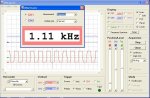
My setup was as follows, Picaxe 28x2 (axe401) running the simple code at default 8Mhz.
Scope channel 1 connected to B.0 (of course). The result is the first image. Everything fine.
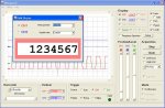
I then closed the DMM window, re-opened it and the result is the second image. Both drop-down menus in the DMM window only show 'Combo1'. The problem could only be resolved by restarting the DPScopeSE software.
I am probably doing something really stupid though so if this is the case, please ignore
On another point, I have been playing with the DPscopeSE v1.02 software and think I may have found a problem.
See the two images below.
My setup was as follows, Picaxe 28x2 (axe401) running the simple code at default 8Mhz.
Code:
Main:
toggle B.0
Goto MainI then closed the DMM window, re-opened it and the result is the second image. Both drop-down menus in the DMM window only show 'Combo1'. The problem could only be resolved by restarting the DPScopeSE software.
I am probably doing something really stupid though so if this is the case, please ignore
No, not stupid. I can actually reproduce this behavior. I'll look into it tonight. Somehow the controls seem to lose their contents, this is the default content at startup; no idea how it makes it back in. But probably easy to fix or work around.
Just keep suggestions and bug reports coming, this makes it a better instrument!
Just keep suggestions and bug reports coming, this makes it a better instrument!
Head imploded.I think the confusion comes from what you think as "open input". It means "not connected to anything", as opposed to "connected to a low-impedance source driving 0V".
So seeing 2.75V ish with nothing connected to the scope, no probes nothing connected to the input, is OK and does not indicate a problem with my building?
OK new question. Scope software V1.02
Set up a Picaxe 18M2 with a simple program running to switch outputs high / low so I can see the scope is working.
setfreq m16
main:
high b.7
high b.6
low b.7
low b.6
goto main
Scope probes connected to the correct outputs.
With scope software set to 0.5 ms/div and trigger auto I can see a rough square wave on both channels, as i expected.
If I try 0.2ms /div (or faster) auto trigger turns off (i can't select auto) and trigger is set to CH1, doesn't matter if its rising or falling getting same results, I then get no results displayed and the trigger indicator does not change.
As soon as I change back to 0.5 ms/div I get a display as expected.
Womai
Finished building the scope and it worked first time. Excellent instructions thanks.
Could I make a couple of suggestions for the documentation?
In step 21: Offset Adjustment Part 1 you say to connect the grabber probes together. I have never touched an oscilloscope in my life before and as I had bought the adjustable probes I was not sure whether to use 1:1 or 1:10. I used 1:1 as I presume this is the same as the grabber probes but you may wish to include a comment on this.
At the bottom of the same page you refer to adjusting the trimmers so that they are exactly at the height of the red and blue arrows. I cannot find arrows as such – just the stepped blue line shown on the screenshot on the next page. The screenshot shows the blue and red line above and below the dotted line and have adjusted it so. I presume that I do need a gap between the two, or is this to illustrate the arrow position? On the next page the lines appear to be together. Some confirmation whether you need the gap or not may assist a novice such as me.
Thanks for all your hard work in producing this kit.
eggie
Yes, it's not a bug, it's a feature!So seeing 2.75V ish with nothing connected to the scope, no probes nothing connected to the input, is OK and does not indicate a problem with my building?
Have a look at the scope schematic:
http://www.pdamusician.com/dpscope/files/DPScope_SE_V1_1_schematic.pdf
On CH1 resistors R16, R17, and trimmer R12 form a voltage divider with low (~100 Ohms) impedance. Once adjusted the midpoint (wiper of R12) will sit at around 2.75V and this will not change noticably no matter what you apply to the input (because the input signal has to go through R1 and R3, 1 MOhm total). So the bottom of the divider built from R1, R3 will always be at 2.7V.
First, connect the input (top end of R1) to ground = 0V. So the divider R1, R3 is at 0V on one end and at 2.75 on the other. The voltage between R1 anbd R3 (which goes to the opamp) is then
Rout = 2.75V + (0V-2.75V) * R3/(R1+R3) or 2.5V (this is what you adjusted to - the scope assumes 2.5V corresponds to 0V on the input).
Second, leave the output open = unconnected to anything: No static current flows anywhere. R1 does not go anywhere. R3 attaches to R1 (through which no current flows) and to the op-amp input (which does not sink any current either) on one end, and to the wiper of R12 on the other). So The top end of R3 will be at the same level as R12's wiper, i.e. 2.75V. The scope knows the divide R1, R3 has a divide ratio of 1:10. The voltage difference to zero level is (2.75V - 2.5V) = 0.25V. 0.25*10=2.5V, this is what you see on the screen.
Suggestions are always welcome!Finished building the scope and it worked first time. Excellent instructions thanks.
Could I make a couple of suggestions for the documentation?
In step 21: Offset Adjustment Part 1 you say to connect the grabber probes together. I have never touched an oscilloscope in my life before and as I had bought the adjustable probes I was not sure whether to use 1:1 or 1:10. I used 1:1 as I presume this is the same as the grabber probes but you may wish to include a comment on this.
At the bottom of the same page you refer to adjusting the trimmers so that they are exactly at the height of the red and blue arrows. I cannot find arrows as such – just the stepped blue line shown on the screenshot on the next page. The screenshot shows the blue and red line above and below the dotted line and have adjusted it so. I presume that I do need a gap between the two, or is this to illustrate the arrow position? On the next page the lines appear to be together. Some confirmation whether you need the gap or not may assist a novice such as me.
If you have the scope probes (not the grabbers), set them to 1:1 when you do the adjustments. The 1:10 mode is not implemented in the PC software yet (I hope to do that tonight) - it needs some fiddling with the offsets.
Arrows - look at p. 27 (step 22, part 2) - the blue arrow is circled with a thick dashed circle. The red arrow hides behind the blue one in this picture. These arrows indicate 0V in the plot. No need for a gap between the red and the blue signal trace. The important thing is that the blue trace is at the height of the blue arrow, and the red trace at the height of the red arrow, wherever these arrows may be vertically.
That's because at 0.2ms/div and faster acquisition has uses equivalent time sampling which has to do repeated acquisitions to show a full trace. (I'm not going to explain this in detail here - the soon-to-be-uploaded user manual has that already).With scope software set to 0.5 ms/div and trigger auto I can see a rough square wave on both channels, as i expected.
If I try 0.2ms /div (or faster) auto trigger turns off (i can't select auto) and trigger is set to CH1, doesn't matter if its rising or falling getting same results, I then get no results displayed and the trigger indicator does not change.
As soon as I change back to 0.5 ms/div I get a display as expected.
The fact you don't get a trigger is most likely because the trigger threshold is initially set to 0V, the Picaxe produces a square wave going from close to 0V to close to 5V, so the signal never crosses the threshold. Move the trigger level up to ~2.5V (third vertical slider in the Position/Level frame, labeled "Trig") and you should be fine.
Just uploaded the first cut of the user manual on my website: www.dpscope.com --> DPScope SE --> Downloads
I also attached it to this post.
I tried hard to make it tutorial-like and readable, let me know if that was successful or not.
I also attached it to this post.
I tried hard to make it tutorial-like and readable, let me know if that was successful or not.
Attachments
-
931.8 KB Views: 15
BillyGreen1973
Senior Member
Thanks for the manual. Very good and easy reading too.
Just one thing I didn't find in the manual, and I am a little curious about it too. What is the 'P' pin on the Logic Anylizer port for? Thanks again
Just one thing I didn't find in the manual, and I am a little curious about it too. What is the 'P' pin on the Logic Anylizer port for? Thanks again
That's for "Power" - routes out the 5V USB supply. You can hook up e.g. a breadboard (be careful not to draw more than ~300mA though). But the main reason I put it in is that I contemplate creating some extension boards for the scope - e.g. a signal generator. The logic analyzer port and external trigger would then be used to supply the extension board with power and send data back and forth. That way the extension board could be very cheap and simple since it does not need to have its own USB interface or power supply.
That's because nobody so far identified himself as "Svejk" when he orderedJust the autograph seems to be missing.
"...when I order the next one."
That's a good point, Svejk. For the price of a PCB and PIC chip from womai, you can build up dedicated circuits to stick into your projects as part of their own permanent feature set. It can monitor multiple analog and digital points in the circuitry or gather and display external info being fed to the other circuits.
Wolfgang appears to have created the ultimate project feature add-on with this bd and software. Not too shabby, as we say in the States.