Relay question.

EricD

Member
Can some one please explain what's going on.

I played around with a relay circuit which I need for my project but as I don't have a BCX38C on hand I tired using a Bd 477 and a c546. The relay didn't lach with neither of the transistors wires as in the manual but both work if I place the transistor above the relay but only if I connect the base directly to the +5V rail, none of them work if I try to connect them to the Picaxe pin.


1) Is this because both the transistors draw more than the 20mA the can source?


2) Is it ok to place the transistor above the relay or is there a reason why this should not be done either directly to the +V rail or using a Picaxe?


Thanks.
 

Goeytex

Senior Member
Neither of the two parts you mentioned show to be valid transistor part numbers. Can you provide datasheets or a link for these?
I have never heard of either. Are they NPN?.. PNP? What voltage rating ? What current ?

Do a google search of "transistor switch". You should find the correct way to wire up either a PNP or an NPN.

Sounds like you may have PNP transistors.
 

EricD

Member
Hi Goeytex, thanks for your reply. I made a mistake with one of the transistors, it should be BD436, not BD477, no idea how I could make such a typo.

Anyway, the C546 I can only guess is a 2SC546 which my "very old" transistor book says is an NPN, 30V, 0.03A, 0.15W. I can't find any data on this one on the Internet except for a Chinese/Japanese site which I can't read. I got a few of these off a gas boiler control pcb.

The BD436 is given as an NPN, 22V, 4A, 36W. Link: http://www.fairchildsemi.com/ds/BD/BD434.pdf

I did as you suggested and have found a "Using Transistors As Switches" site, I'll read through that in the hope that I'll understand enough to finish my project.


Thanks again.
 

SAborn

Senior Member
Hmmm! you are wrong on the BD436 its a PnP transistor see data sheet here........ http://www.datasheetcatalog.org/datasheet/stmicroelectronics/4127.pdf

The 2SC546 (if thats what it is) could be a NpN according to the data sheet here.....http://www.datasheetcatalog.org/datasheet/toshiba/3320.pdf

Or perhaps its a BC546, as you see 2 different packages with different pin outs so it could be anything.
http://www.datasheetcatalog.org/datasheet/motorola/BC546B.pdf

A basic schematic of what you have setup would help too.
 

westaust55

Moderator
An NPN transistor such as the BCX38C depicted in the diagram in PICAXE manual 3 page 8 is suited to "low side" switching - that is, where the transistor is on the negative/0V side of the load.

A PNP transistor is better on the high/supply side of the load but can give problems is used alone. If the PICAXE supply voltage is less that the voltage used to supply the load, the PICAXE output cannot when set high be high enough to turn off the transistor. Thus for proper control of a PNP transistor when used for switching of higher voltages an interface such as a NPN transistor is needed between the PICAXE and the load switching transistor.

As suggested by SAborn, a schematic showing the circuit you are proposing, and clear information as to the transistors you are using will help us to better guide you.
If you have a circuit built then even a clear photo of the circuit where we can check transistor connections and wiring ends can be helpful and has helped folks here spot errors in the past.
 

srnet

Senior Member
And it would be necessary to know the details of the relay you are using, there are lots and lots of different types, its so difficult for us to guess. .
 

Goeytex

Senior Member
Eric,

Why not just spend the 20 cents (pence?) ea. and get some transistors that you KNOW are NPN General Purpose ?
Guessing about with junk from an old board can get frustrating, especially if you do not have much experience.
 

Dippy

Moderator
Exactly.
If chopping up old boards your FIRST task should be to check the components actually work and that you can precisely define them (spec and pinout). So, number 1, do they work and are they man enough for the job?
I hope your bits work, but if you discover next week that you've been using duffers this will cause a lot of eyebrow oscillation.

Yours may be fine and it's just that you've made a wiring mistake.
But, unless you can define the parts, or give us a link, or prove the parts work, or give us a drawing, or say "it's exactly as Manual3 page whatever" then it's tricky to nail it rapidly.
Most small transistors will be able to drive a small relay.
 

EricD

Member
Hi all, thank you all very much for replying.

It was quite late last night as I started playing with the relay switching and hence why I decided to try out the transistors from the old boards. I did test the transistors and they all work, they do switch the relay on if the relay is on the negative side but not if I connect as in the picaxe manual or if connected to the out pin of picaxe.

One transistor that I tried was, according to specs on the Internet, a Darlington but even that didn't work as per the picaxe manual schematic.


I will do some drawings later on and post the specs of the relay a well.

Thanks
 
Last edited:

SAborn

Senior Member
To be honest with you Eric not much of your last post makes any sense in the electronic world, and almost goes against how electronics are meant to work, so it would seem things have worked due to good luck rather than correct design.

As dippy has said, working with secondhand junk can cause more problems than it will solve, and without the ability to test it correctly you really have no idea if it works correctly or not.

You claim to have tested it.................well sorry! but i dont see how, as what you stated the tranny as, was not what it is, so how could you have tested it and actually know if it works. (one you can not find a data sheet for, and the other is wrong to what you think it is)

I have a 100 or more transistors in the workshop that will all drive your relay as per the manual circuit, but not one of them is a PnP transistor, all NpN including the darlington ones.

It is obvious you didnt even look at the data sheet i posted a link to earlier for your BD436 transistor.
 

cdngunner

Senior Member
Easy there young fell. Can't rip him a new one till he has at least 20 posts.

p.s I can see though, how you guys get frustrated having to deal with the same novice questions and errors time and time again. I guess people have to start somewhere.

p.p.s ewwww...a tranny (maybe it just has a different meaning in Canada)
 

SAborn

Senior Member
Can't rip him a new one till he has at least 20 posts.
My bad! i should have waited for another 4 posts of incorrect information before making a comment.

p.p.s ewwww...a tranny (maybe it just has a different meaning in Canada)
I would have thought this thread fitted the "tranny" expression very well, due to the fact the tranny in question here is not the same sex as it was thought to be. I wonder what part numbers are stamped on the trannys you have in Canada.
 

cdngunner

Senior Member
Didn't we have a primer on how to ask a question.? :D if not maybe we should have a sticky. Give all your valueable insights ONCE and then just refer all people lacking of info in their posts there...
 

Reloadron

Senior Member
Hi Eric

Those nice people in PICAXE land did a very, very good job with this manual showing interface circuits. They placed some thought into suggesting the transistors they did in the manual. However, the end user (that being you) needs to consider a few things. When a transistor is used to drive a relay coil it becomes real important to have the data sheet handy for the relay that will be used. The end user needs to know the relay coil voltage and current (or the relay coil DC resistance). The relay coil is a load and the transistor will be switching that load on. The transistor will in this case be acting as a switch, something transistors are not always used as.

When using a transistor as a switch we say that we want to drive the transistor into "saturation" which is a way of saying we will turn the transistor as On as On can possibly get. When a transistor is driven into saturation it is basically acting like a switch or a straight piece of wire between the emitter and collector (discounting a small voltage drop across the transistor junctions). The base resistor as well as the transistor characteristics play an important roll in making sure we get the transistor into its saturation region.

Looking at the manual we see they use in many applications the NPN darling little darlington transistor BCX38C. Now if we look at the BCX38C data sheet we can look at the data, scroll down and see Base-Emitter turn on voltage is about 1.8 volts to get the transistor on with an 800 mA load (the max current for this transistor). That voltage and subsequent Base Emitter current is going to be controlled by the base resistor using some formulas we won't get into but a Google of "transistor base resistor value" will bring up several links like this one that explain things in great detail.

While having a bucket of assorted transistors lying around can be a good thing, it can also be a bad thing resulting in damage to your PICAXE chip(s). Remember that little PICAXE chip needs to source enough current to fully turn on the transistor with a calculated base resistor or it might die a horrible death trying. Again, this is why those nice people at PICAXE suggested the transistors they did as a very good guideline to work with. Using a random transistor can lead to bad things happening sans a full understanding of exactly what is going on. I would strongly suggest just investing in a pile (they are inexpensive) of the transistors called out in the PICAXE manual until you have a good working knowledge of transistors in general.

Just My Take
Ron
 

EricD

Member
To be honest with you Eric not much of your last post makes any sense in the electronic world, and almost goes against how electronics are meant to work, so it would seem things have worked due to good luck rather than correct design.
Not being an expert I tried to explain as best as I could. Sorry that it wasn't enough, I'll try harder next time.

As dippy has said, working with secondhand junk can cause more problems than it will solve, and without the ability to test it correctly you really have no idea if it works correctly or not.
Yes, I do know that but as it was late in the evening and I had nothing better to do, I just decided to play around a little. I paid for it with blowing up 3 of the C546's but as the board had 15 of them and they didn't cost anything it didn't really matter. BTW, they blew up before I connected them to the Picaxe so there was no danger to the chip, if anything I could only have blown the powersupply maybe, of which I have about 25 so that doesn't matter either.

You claim to have tested it.................well sorry! but i dont see how, as what you stated the tranny as, was not what it is, so how could you have tested it and actually know if it works. (one you can not find a data sheet for, and the other is wrong to what you think it is)
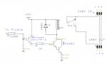
Well, I tested them with a Digital Multitester and as I stated in my first post I did say that I got the relay to switch as in "Figure 3" in the attachment included with this post (hopefully included anyways).

I have a 100 or more transistors in the workshop that will all drive your relay as per the manual circuit, but not one of them is a PnP transistor, all NpN including the darlington ones.
I have about 20 or so and two are PNP's, pot luck I guees seen as they all came off old boards.

It is obvious you didnt even look at the data sheet i posted a link to earlier for your BD436 transistor.
Sorry but if you were to bet on that you would lose because if you see the link I posted in my second post the data sheet I posted is the same as yours albeit on a different site. Also I mentioned that I have a "very old" transistor book and I looked up the data in there for both transistors. The book is "Jaeger Electronic '93", as I said, very old. In the book and both yours and my link state the transistor as "PNP" and very stupidly I made a mistake and typed in "NPN". I am very sorry about that, will not happen again.

As for testing, long ago at the age of 42 I attended Evening Classes for 3 years here in the UK for Electronics and did learn a few things, not much but enough to have learned how to test transistors and a few other things but as you can see I am definitely not an expert. I am now 59 and only do Electronics for fun more than anything else and only build things that I need for my other hobby, woodworking. This one I am working on now is intended to be a "Downcounter" with a relay to switch ON and OFF a UV Box that I use to expose the Photoresist copper boards. I only use it probably 3 - 4 times a year but as it's winter and too cold in the garage I decided to build the timer unit, it would be usefull and also helps to pass the time.

I could not find any info on the transistors last night but managed to find the same ones on Ebay just now. They are exactly the same except for the " PHB ?" at the bottom, on mine it says "W 43". Link: http://www.ebay.co.uk/itm/1-Transistor-Component-Brand-New-Typical-Use-LCD-TV-C546B-/280771943963

At the evening classes, and by a few other electronics experts, I was told that any transistor that starts with a "C***" should be looked/searched under as "2SC***", that number is in my book and I tested it them accordingly.

BTW, before anyone thinks that I am a lazy sod who does not want to work and gets bored at home with nothing to do, sorry but that is not the case. Well, no I don't work, neither am I a student trying to use you guys to pass my exams. I am sitting at home waiting for a heart bypass surgery and a couple of other surgeries all within this year, hopefully. And trying to learn whay I don't know, which is quite a lot.

Anyway, if a novice hobbyist is not welcome here please let me know and I'll take my questions elsewhere.

Thanks for taking the time to reply.

Regards

EricD


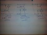
PS: I have attached the three (hand drawn) circuits that I tried last night, hopefully that would expalin what I was trying to expalin. I tried the circuits with both transistors but obviously not both at the same time.


PPS: The relay is 6V, the coil is 80ohms. According to the date it will switch 4.5 to 7.8 volts, must release voltage >0.6v. Bought that one from Maplins, didn't come off any of the boards I salvaged the transistors from.


Relay.jpg
 
Last edited:

EricD

Member
My bad! i should have waited for another 4 posts of incorrect information before making a comment.
Well, three more to go and then you can really "lay it on". :eek:


I would have thought this thread fitted the "tranny" expression very well, due to the fact the tranny in question here is not the same sex as it was thought to be. I wonder what part numbers are stamped on the trannys you have in Canada.
The "sex" was correct just the "title" was wrong, price one pays for not being an expert and is somewhast reluctant to ask question odfr fear of making a fool of himself and it seems that my fears were justified. :(
 

EricD

Member
Hi Eric

Those nice people in PICAXE land did a very, very good job with this manual showing interface circuits. They placed some thought into suggesting the transistors they did in the manual. However, the end user (that being you) needs to consider a few things. When a transistor is used to drive a relay coil it becomes real important to have the data sheet handy for the relay that will be used. The end user needs to know the relay coil voltage and current (or the relay coil DC resistance). The relay coil is a load and the transistor will be switching that load on. The transistor will in this case be acting as a switch, something transistors are not always used as.

When using a transistor as a switch we say that we want to drive the transistor into "saturation" which is a way of saying we will turn the transistor as On as On can possibly get. When a transistor is driven into saturation it is basically acting like a switch or a straight piece of wire between the emitter and collector (discounting a small voltage drop across the transistor junctions). The base resistor as well as the transistor characteristics play an important roll in making sure we get the transistor into its saturation region.

Looking at the manual we see they use in many applications the NPN darling little darlington transistor BCX38C. Now if we look at the BCX38C data sheet we can look at the data, scroll down and see Base-Emitter turn on voltage is about 1.8 volts to get the transistor on with an 800 mA load (the max current for this transistor). That voltage and subsequent Base Emitter current is going to be controlled by the base resistor using some formulas we won't get into but a Google of "transistor base resistor value" will bring up several links like this one that explain things in great detail.

While having a bucket of assorted transistors lying around can be a good thing, it can also be a bad thing resulting in damage to your PICAXE chip(s). Remember that little PICAXE chip needs to source enough current to fully turn on the transistor with a calculated base resistor or it might die a horrible death trying. Again, this is why those nice people at PICAXE suggested the transistors they did as a very good guideline to work with. Using a random transistor can lead to bad things happening sans a full understanding of exactly what is going on. I would strongly suggest just investing in a pile (they are inexpensive) of the transistors called out in the PICAXE manual until you have a good working knowledge of transistors in general.

Just My Take
Ron
Hi Ron, this is exactly the answer I was looking for, thank you for taking the time to explain in such detail, really appreciate it.

Yes, very true that the transistors cost pennies but as it was late in the evening and I could not get them I decided to practice on what I had. And because I blew up three of them last night it is a cheap/er way of practicing instead of blowing up the BCX38C's.

As far as I knew/know any transistor could be used as a switching transistor, or most anyway, NPN or PNP and when I could not get those to work I wanted to know why, hence this thread.

Thanks again.

EricD
 

EricD

Member
Easy there young fell. Can't rip him a new one till he has at least 20 posts.
Only three more to go. :)

p.s I can see though, how you guys get frustrated having to deal with the same novice questions and errors time and time again. I guess people have to start somewhere.
Everyone has a choice, reply or ignore. ;)

p.p.s ewwww...a tranny (maybe it just has a different meaning in Canada)
Means the same here in the UK as in Canada, no idea about anywhere else though. I've never heard of any transistor changing sex and becoming a "tranny" though. They might be "working bits", get a little "hot" and "blow their tops off" sometimes but a sex change.......? :D
 

cdngunner

Senior Member
Don't take it personally. Part in parcel of this being an educational pic. Unfortunately there are a lot of people just starting out who do not understand the fact that they have to supply as much info as possible to get as best an answer as possible. I assume newbies have no idea of the millions of variations of anything to do with electronics. Teachers should teach the best way for students to go about getting the info they need. This should include a session of what info to include.
 

EricD

Member
Don't take it personally. Part in parcel of this being an educational pic. Unfortunately there are a lot of people just starting out who do not understand the fact that they have to supply as much info as possible to get as best an answer as possible. I assume newbies have no idea of the millions of variations of anything to do with electronics. Teachers should teach the best way for students to go about getting the info they need. This should include a session of what info to include.
I agree 100% with you but that's what being a "newbie" is all about, isn't it? Not knowing what to ask, exactly how to ask it and the "lingo" of the particular subject. But, if the info the "newbie" has supplied isn't enough then all one has to do is ask (or tell) the person to supply (post) more data and explain a little more. Or, if one is not interested in getting in to a conversation with a newbie than one has the choice to ignore newbies and only corrospent with those who know what they are talking about.

As far as I am aware, our teacher at the evening classes explained things perfectly but that was 17 years ago and we do tent to forget things that we have not had any dealings with for such a long time. Although I do have City & Guild in Electronics never worked in the industry so all I know is what I learned at colege, of which I have forgotten quite a lot. It takes a while to "get back in", especially as technology has changed so much since then.

I have learned quite a lot in this thread, not only about transistor switching but also how not to ask questions in the future. Next time, I won't post late in the evening, I'll leave it till the next day when I have more time to think about what I want to ask, and I'll try my "bestest" not to give "Trannies" a sex change. :D
 

Reloadron

Senior Member
Hi Eric

I looked at your drawing. When you draw basic switching transistors that are not identified in the drawing things go better for those viewing it if you use the correct NPN or PNP symbols. Those pesky little emitter arrows help a lot. :)

Attached is a cartoon depicting how you would want to connect a simple relay switching circuit using a NPN or PNP transistor. I used a 2n3904 and 2N3906 simply because they are complimentary. The NPN being on when the base is logic high and the PNP being on when the base is logic low.

Hope this helps with configuring transistors.


Ron
 

EricD

Member
Hi Eric

I looked at your drawing. When you draw basic switching transistors that are not identified in the drawing things go better for those viewing it if you use the correct NPN or PNP symbols. Those pesky little emitter arrows help a lot. :)

Attached is a cartoon depicting how you would want to connect a simple relay switching circuit using a NPN or PNP transistor. I used a 2n3904 and 2N3906 simply because they are complimentary. The NPN being on when the base is logic high and the PNP being on when the base is logic low.

Hope this helps with configuring transistors.

Ron
Hi Ron, thanks for the explanation and the drawing, a great help. I have saved the drawing and will use it as reference in the future.

Re: the PNP transistor, would I need a "pullup" resistor to make sure the transistor is completely turned off or is it enough just to put the picaxe pin high?

Also, you have both types on the 0V rail, would they still work if they were connected to the +V rail and the relay on the 0V?

What is the difference in "negative ground configuration" and "positive ground configuration" , when is one preffered to the other or does it not really matter?

Thanks

Eric
 

nick12ab

Senior Member
I'm learning too - regarding the PNP transistor, doesn't it require a negative voltage to turn on in Reloadron's circuit?
 

EricD

Member
EricD

Honestly, the vast majority of respondents here are
"newbie-friendly".
I know mate, I have been doing a lot of reading in this forum and have a good idea.

However, you may need to allow for cultural nuances. :))
4 years in the Royal Engineers teaches a lot about "cultural nuances". ;)

Thank you for the links, they will be a tremendous help. I did find another site but not as comprehensive as these ones.
 

Goeytex

Senior Member
@Reloadron

You may want to consider moving the PNP in the diagram to the high side. As a low side switch it will have to dissipate a lot more heat and may not even work properly with an inductive load.

@Eric

It may seem that you have been jumped on a bit and maybe you have been a little. Take it with a grain of salt. The folks here are really good eggs and really want to help, and ... the only real reward is to see a problem solved and / or knowledge gained. At least you now know what is expected in order to get proper help. After seeing you push back a little I think you will fit right in here.

Good luck with the surgeries. I had a bypass in 2001 and then recently arterial bypasses in both legs. Was in a wheelchair for almost two years with the leg stuff and that's what got me going with the Picaxe stuff. Lots of time on my hands. Now with good legs again I'm hooked on Picaxe stuff and programming in general but now I can take a break and run a mile when I want to.

Take care.
 
Last edited:

Reloadron

Senior Member
Thank You Goeytex as yes, I could have done a better job with that PNP circuit. While it looked good beside the NPN circuit it was not good design practice. This being especially true considering as you mention the relay being an inductive load, so Eric you may want to drop that half of my little cartoon or use it as an example of not the best way to go about it. :)

This is a good link covering using transistors as switches and includes the same transistor I used but using it in the configuration Goeytex points out. Additionally Eric, note Figure 1 and the use of R2 which is what I believe you were getting at.

Thank you again Goeytex for pointing out my poor design practice.

Ron
 

Goeytex

Senior Member
I'm learning too - regarding the PNP transistor, doesn't it require a negative voltage to turn on in Reloadron's circuit?
That would be correct nick, and is one of the reasons why most PNP switches are on the high side where full conduction is easy.

As drawn, with the base at 0v the transistor is "almost" fully on, but still in the linear region and will have to dissipate more heat than is necessary. IT need to go about to about -.7v to saturate. High side switching with a PNP does not have this problem.
 
Last edited:

EricD

Member
@Reloadron
@Eric

It may seem that you have been jumped on a bit and maybe you have been a little. Take it with a grain of salt. The folks here are really good eggs and really want to help, and ... the only real reward is to see a problem solved and / or knowledge gained. At least you now know what is expected in order to get proper help. After seeing you push back a little I think you will fit right in here.
Compared to some other forums I have been on (ie: political forums) what I have seen here is very mild and water off ducks back as the saying goes. I see every posting as gaining more knowledge in one way or another.

Good luck with the surgeries. I had a bypass in 2001 and then recently arterial bypasses in both legs. Was in a wheelchair for almost two years with the leg stuff and that's what got me going with the Picaxe stuff. Lots of time on my hands. Now with good legs again I'm hooked on Picaxe stuff and programming in general but now I can take a break and run a mile when I want to.

Take care.
Thanks Goeytex, I'm not looking forward to the surgery but have no choice but to go for it. I don't think I will ever be able to run a mile but I am looking forward to being able to walk more than 50 - 100 yards without gasping for air.

I joined an electronics forum last year because I wanted to build an RPM meter for my woodlathe and other woodworking machines I have. It was there that it was suggested I go for the picaxe. I've bought most of the parts to make that circuit but still haven't finished it. I want to get this countdown timer working first so that I may be able to produce better PCBs using my UV exposure boxes. I experimented making PCBs with a laminator and had pretty good results but I have two UV boxes which I want to use in the hope that I get even better results.

Electronics is just a hobby mainly in the winter time when it's too cold to do woodworking in my garage full of holes.

Thanks
 

EricD

Member
This is a good link covering using transistors as switches and includes the same transistor I used but using it in the configuration Goeytex points out. Additionally Eric, note Figure 1 and the use of R2 which is what I believe you were getting at.
Ron
Your link and Goeytex's reply re: "moving the PNP in the diagram to the high side" has answered my question re: "negative ground configuration" and "positive ground configuration".

Thank you both.
 

EricD

Member
I used the DesignSpark PCB Schematic and PCB design program to make the schematics in the attachement. It is basically the same as the example schematic included with the program. I just added the opto isolator (CNY17F-3) and changed the relay to another one which is closer to the one I will be using. Also, because the CNY17F-3 part is not included in the parts library I used the one nearest to it.

I have also added 2 x 3 Pole headers where the 240V in and out will be connected.

LINK for the CNY17F-3: http://www.datasheetcatalog.org/datasheet/toshiba/2212.pdf

Are the two resistors, R1 and R2, correct values? I used 330R (R1) for the LED in the opto isolator because that is the one usually used for LEDs and the 1K (R2) because it's used in the original schematic to switch the BCX38C on.

Should I be looking at the "Forward Current (IF)" when calculating the resistor for the LED in the opto isolator which is given as 60mA in the datasheet?

Should I be instead using a DPDT relay for the high voltage?

Thanks
 

Attachments

MartinM57

Moderator
Eric

Even as a relative beginner, it's always worth asking yourself (or other sources - like here) why components exist in a schematic. IMHO the opto adds nothing apart from complexity and doesn't really isolate anything, since you have the output side powered by the same 5v that powers the PICAXE. So any mains side leakage onto the rhs of the opto (if that's what you think you are trying to isolate) will get onto the PICAXE supply and spoil everything big time...
...which brings the second point that you should really be looking for a solution that doesn't need mains switching (for safety). Is there a low voltage circuit in your UV box that you can switch instead? (but yes, a DP relay would be much better than what you have)
 

Reloadron

Senior Member
@ Eric, before I forget (again) best wishes for a speedy recovery. While surgery isn't something to look forward to, we come away from it better off than going in. So again, best wishes for a speedy recovery.

@ Martin, yeah, generally when optical isolation is employed different power supplies are used.

Ron
 

EricD

Member
Eric

Even as a relative beginner, it's always worth asking yourself (or other sources - like here) why components exist in a schematic. IMHO the opto adds nothing apart from complexity and doesn't really isolate anything, since you have the output side powered by the same 5v that powers the PICAXE. So any mains side leakage onto the rhs of the opto (if that's what you think you are trying to isolate) will get onto the PICAXE supply and spoil everything big time...
...which brings the second point that you should really be looking for a solution that doesn't need mains switching (for safety). Is there a low voltage circuit in your UV box that you can switch instead? (but yes, a DP relay would be much better than what you have)
Hi MartinM57, thanks for your reply, I see what you mean. Unfortunately there is no low voltage in the UV box hence the reason why I need the isolation. So what I really should be looking at are two separate PCBs, one for the Picaxe circuit and one for the relay circuit and power them up with two separate power supplies?

I have a few stabilised 5V power supplies which I could use to power each PCB separately. I think there is enough room in the box for the two PCBs and both the power supplies.

Maybe build them all in a separate box with a socket outlet and use it as an external timer?

Thanks again.
 
Top