I am hoping that someone can help me with some advice or confirm what I suspect.
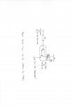
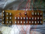
I have built a large relay board for a model railway project. The circuit used for each element is based on the interface circuit in section 3 of the manual. I have used a MPSA13 transistor in place of the BCX38C. The relays have 12v coils (as there are over 30 I opted for the higher voltage in order to reduce the load on the 5v supply to the unit and not exceed the output capability of the PICAXE by driving a large number of relays directly). All the relays are fitted with the requisite diode, and a 1k resistor connected to the base of the transistor. The relays have a coil resistance of 700 - 720 ohms. As the board needs to be mounted into a 19" rack case with a 24v PSU (don't ask...!) and 4x 40X2 control boards there isn't an awful amount of room to spare. So to my problem...
Prior to mounted the board in the case and connecting up the 100+ wires from the boards to the connectors I thought it would be wise to test the relays. I have a bench supply supplying 12v and 5v and this was connected (the two respective grounds connected to the relay common return) to the power supply rails on the board. I then touched the wires from a number of the transistor bases to the 5v rail; nothing happened (I have checked that the necessary voltages are present on the board where they should be, and they are). Touching the base wires to 12v and the relay switches over. I replaced one of the MPSA13 transistors with a BCX38C with the same effect; works on 12v, doesn't work with 5v.
I suspect that high relay coil resistance is preventing sufficient current to be drawn to saturate the transistor at the lower voltage. If that is the case, does anyone have any suggestions to get it to work at the lower voltage? If it isn't the reason, all suggestion gratefully received. Replacing all the relays for 5v coil examples will cost in excess of £50, and I would rather not do that.
")