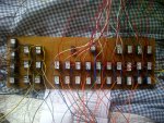
Relay interface circuit

Peterrey

New Member
I am hoping that someone can help me with some advice or confirm what I suspect.

I have built a large relay board for a model railway project. The circuit used for each element is based on the interface circuit in section 3 of the manual. I have used a MPSA13 transistor in place of the BCX38C. The relays have 12v coils (as there are over 30 I opted for the higher voltage in order to reduce the load on the 5v supply to the unit and not exceed the output capability of the PICAXE by driving a large number of relays directly). All the relays are fitted with the requisite diode, and a 1k resistor connected to the base of the transistor. The relays have a coil resistance of 700 - 720 ohms. As the board needs to be mounted into a 19" rack case with a 24v PSU (don't ask...!) and 4x 40X2 control boards there isn't an awful amount of room to spare. So to my problem...

Prior to mounted the board in the case and connecting up the 100+ wires from the boards to the connectors I thought it would be wise to test the relays. I have a bench supply supplying 12v and 5v and this was connected (the two respective grounds connected to the relay common return) to the power supply rails on the board. I then touched the wires from a number of the transistor bases to the 5v rail; nothing happened (I have checked that the necessary voltages are present on the board where they should be, and they are). Touching the base wires to 12v and the relay switches over. I replaced one of the MPSA13 transistors with a BCX38C with the same effect; works on 12v, doesn't work with 5v.

I suspect that high relay coil resistance is preventing sufficient current to be drawn to saturate the transistor at the lower voltage. If that is the case, does anyone have any suggestions to get it to work at the lower voltage? If it isn't the reason, all suggestion gratefully received. Replacing all the relays for 5v coil examples will cost in excess of £50, and I would rather not do that.
 

Dippy

Moderator
Shouldn't be a problem if you've done it correctly - assuming I have understood your description.
I don't think those relay coil resistances will have much effect, in fact it should be fine.
Are you supplying 12V to the 'top' of the relay coil?
Sounds like you are on the 'edge' where 5V is just too low and 12V is just enough - doesn't sound very good.


I saw one data sheet for MPSA13 which says Vce(sat)=1.5V, so what is the pull-in voltage (min) for your chosen relay.
Why are you using Darlingtons, what's wrong with little trannies which have a far lower Vce? Perfectly OK when selected properly.
I'm not even going to mention MOSFETs ;)


It really helps if you provide an EXACT schematic of one relay as an example.
If you just spend 10 minutes doing an accurate drawing it really can help with unambiguous information without loads of questions being asked of you.
On your schematic make it CLEAR what voltages are applied where.
And, don't forget, it's up to you to check values of components and connection accuracy.
 

erco

Senior Member
Your 1K base resistor sounds high to me, but then I primarily use 2N2222A's for switching big relays, where a 330-470 ohm resistor does fine. Still, that might be your simplest option if it works for you.

Your setup sounds impressive, just the power to switch and hold your relays is considerable. I'm a relay fan, I have stockpiled a number of the cheap multi-relay boards off ebay: http://www.youtube.com/watch?v=rHzxgpUCjiU They are 5V units and come ready to go with driver transistors installed, microcontroller-ready.

I also stocked up on latching relays when they were a dollar, which stay on or off without consuming anypower. They only need a quick blip of power to change their state. My favorite Aromat latching relays are particularly well-suited for use with microprocessors. They are 5V DIP units, low enough coil current where they can be driven directly by a microprocessor (28 mA for a quarter second, so no driver transistor needed) and the two coil pins get reversed to latch or unlatch the relay. That means that 28 individual relays could be controlled using just eight microprocessor pins. I'm still looking for the right application to take advantage of that!

http://pdf1.alldatasheet.com/datasheet-pdf/view/197272/OMRON/G6HU-2.html
 
Last edited:

srnet

Senior Member
They are 5V DIP units, low enough coil current where they can be driven directly by a microprocessor (28 mA for a quarter second, so no driver transistor needed)
The maximum quoted sink\source current for the 40X2 (18f45k22) is 25ma.
 

AllyCat

Senior Member
Replacing all the relays for 5v coil examples will cost in excess of £50, and I would rather not do that.
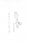
Hi,

There's absolutely no reason why you should have to.

Are you sure the transistors and diodes are wired in the correct way around (a photo might help) and the diode and relay both go to +12 volts ? The Darlingtons should give so much current gain that the relays might operate almost "with a wet finger", let alone with a 1k resistor to 12 volts.

But IMHO the circuit in the manual is really not very clever and in most cases would work better with a humble BC548, particularly with a 5 volt rail. By their nature, Darlingtons normally drop at least 1 volt, which could be significant with only a 5 volt (or worse 3 x AA cells) supply rail. Having a current gain of around 5000, a drive of 3+ mA should be totally unnecessary. My guess is that the Darlington is operating as a single transistor with its "driver" transistor contributing nothing. Well actually less than nothing, with its collector-base diode "stealing" some of the available base current and holding the output device further out of saturation than necessary.

Cheers, Alan.
 

erco

Senior Member
The maximum quoted sink\source current for the 40X2 (18f45k22) is 25ma.
Surely that's a continuous maximum rating. I've used a BASIC Stamp (rated at just 20 mA) to drive these for many, many cycles. I suspect a Picaxe is similarly up to the task, for just 250 milliseconds, followed by a long off period.

Or, have I backed the wrong horse?
 

MikeAusP

Member
. . . . They are 5V DIP units, low enough coil current where they can be driven directly by a microprocessor (28 mA for a quarter second, so no driver transistor needed) . . . .
Because the Relay coil is very inductive, the current will build up slowly, so you could set the pulse width so it would never exceed 25mA.

The biggest problem will come form the Inductive voltage spike when the current is switched off.
 

inglewoodpete

Senior Member
Simple troubleshooting/diagnosis is required.

1. If the circuit works when the base resistor is touched on 12v but not 5v, are the two grounds (0v lines) connected together?
2. What is Vce when the base is open circuit. It should be 12v.
3. What is Vce when the base resistor is connected to 5v?

In my opinion, a darlington is overkill for a low current relay. Try a BC548, 2N2222 etc instead. The BC548 is what I use to drive 12v relays.

As Mike has already mentioned, with such a high resistance relay coil it will have a larger than normal inductive kick when the transistor is turned off. If the circuit has not been designed with this in mind, you could have problems with the stability of any microcontroller.
 

John West

Senior Member
I should never try to think when I'm very tired, but here goes:

Peterrey, agree with Dippy. I think we need to see both a schematic of what you think you wired, and a photo of how your circuit is actually wired. At this point it sounds like it should work properly if it's wired correctly, although I would have used a lower value (330 to 470 Ohm) base resistor just out of habit in a 5V circuit. Those Darlington transistors you mentioned both have Hfe's of 5K or so, so a single mA into their bases should turn either of them on hard enough to sink whole amps if the load demanded it, (and the transistor could handle it.)

If the load was light, (high coil resistance,) the transistors would still be turned on hard, but would not get warm. The transistors saturate based on the base/emitter current, not the collector/emitter current. So we really need to see how you have things wired. My guess is something's amiss.
 

westaust55

Moderator
Simple troubleshooting/diagnosis is required.

1. If the circuit works when the base resistor is touched on 12v but not 5v, are the two grounds (0v lines) connected together?
I'm with IWP and suggest that the 5V and 12V common/ground lines are not connected.
Or the transistor is connected incorrectly (time for that photo)

With the darlington in saturation Vce is a max of 1.5V and for Ic = 100 mA Ib needs to be 0.1 mA from the datasheet.
Hence with a 5V PICAXE output driving Rbase <= ( Vcc - Vb) / Ib = (5 - 2[max]) / 0.0001 = 30,000 Ohms
so even a 1 K Ohm should operate from 5 Volts with a current of around (3/1000 = 0.003 A) ==> 3 mA.

That said, as the relay coil current will be of the order of 18 mA (700/12) also agree that a BC548 or equivalent rated at 100 ma will certainly suffice
 

Peterrey

New Member
Thanks for your replies

I am hoping that someone can help me with some advice or confirm what I suspect.

For those of you who have replied requesting a circuit diagram Icircuit.jpg have attached a hand drawn schematic of one of the relay elements. Please forgive the poor quality as I am currently at work.

When I have a moment, I will try with a plain old NPN as suggested - I have a number of suitable items available (BC337, etc.). The relays in question are IMO EM2S-CWL-12V supplied by Rapid Electronics (50-1982). The 'Pick Up' voltage published for the 12v variant is 9v.

To reply individually to your comments:

ERCO - I tried applying 5v to the base of the transistor through progressively lower valued resistors, and finally, no resistor. It still didn't work.

SRNET - The problem I have regarding power consumption is that there are 10-15 of these relays connected to each 40X2. The contacts of the relays are not to operate momentarily, but some are expected to stay energised for some minutes, switching the 24v supply mentioned to another unit. To connect that many directly driven relays would exceed the total 'absolute rating' of the whole microcontroller. Using more microcontrollers is not an option.

INGLEWOOD PETE - This is the one thing I didn't check (VCEO with 5v connected to resistor). However, the supply voltages did not dip when power was applied and no excessive supply current was drawn (so no short circuits anywhere - also confirmed with a continuity tester)

WESTAUST55 - The whole board was extensively checked for short circuits. I verified that the two relevent 0v lines were connected together from the board and via disconnected PSU leads. All the transistors/diodes are correctly wired - otherwise it wouldn't work with 12v. The continuity of the 12v supply was checked and verified, as was the continuity of the returns. The returns were commoned on the supply leads and are also commoned on the board (as there is a 74LS86 gate ic on it too).

Does that help everyone with the comments raised?
 

AllyCat

Senior Member
Hi,

I tried applying 5v to the base of the transistor through progressively lower valued resistors, and finally, no resistor. It still didn't work.
That should have destroyed the transistor. If it didn't then something is clearly faulty or not connected.

All the transistors/diodes are correctly wired - otherwise it wouldn't work with 12v.
That's quite a wild assumption. With 12 volts and a 1k series resistor, the relay might operate without any transistor(s) connected at all!

Cheers, Alan.
 

MartinM57

Moderator
I tried applying 5v to the base of the transistor through progressively lower valued resistors, and finally, no resistor. It still didn't work.
...and possibly (probably) may never work again - you can't connect the base of a transistor directly to 5v or 12v with no base resistor at all...it will fail terminally almost straight away :(
..the terminal failure mode might be that consequently applying 12v to the base connection will indeed turn on the transistor

There is nothing wrong with your diagram - it should all work fine.

Can you temporarily replace the one of the relay and diode pairs with a LED plus a suitable in-series resistor (say 1000 ohms) and use a transistor that hasn't had any experiments applied to it?
 

Peterrey

New Member
Hi,


That should have destroyed the transistor. If it didn't then something is clearly faulty or not connected.

Maximum VBEO voltage of an MPSA13 is 10v... I only applied 5v directly to the base.


That's quite a wild assumption. With 12 volts and a 1k series resistor, the relay might operate without any transistor(s) connected at all!

Cheers, Alan.
What ALL thirty five relays on the board - tested individually, wired identically (correctly according to the transistor data sheets)? I would have to be really unlucky to get 30+ duff transistors...
 

AllyCat

Senior Member
Hi,

Maximum VBEO voltage of an MPSA13 is 10v... I only applied 5v directly to the base..
The rating is VEBO which is the reverse breakdown voltage, i.e. the base should not be taken below minus 10 volts. VBE is a forward diode (or 2 in series with a Darlington) and current will flow with about 2 volts VBE, until the device dies (if sufficient current is available).

Cheers, Alan.
 

Peterrey

New Member
I will try your last suggestion with an individually assembled unit. Regarding the earlier comment, my sequence of testing was to try the flying lead connected to the base (via the 1k resistor) by touching on the 5v supply. When it didn't work I then tried it by touching the flying lead to the 12v supply feeding the relay coil. I tried this a number of times. I then tried reducing the base resistor (3x, then 2x, then 1x 330 ohm resistor, then no resistor) and 5v without it working. As a further precaution I actually replaced the transistors on the elements I had tested with 5v directly on the base. As I mentioned there are 35 of these relay elements on the board, and of all the ones I tested none worked. I have just verified again that the MPSA13/BCX38C were connected correctly (using the Rapid datasheet and Allcomponents). I have repeatedly verified that all the grounds are connected, as are all the 12v supplies - for testing purposes I used the relays nearest the supply wires.
 

MPep

Senior Member
Granted. My bad - can't read straight.
Your bad WHAT???


Basic electronic theory dictates that the 5V side is not connected to 12V side.
Why??
Because you've connected the Base to 5V, and still no action on the relay. You connect to Base (via a resistor, ALWAYS!!) to 12V, and the relay works.
To test, use a multimeter and connect the negative lead to the 0V of the 12V supply. Then see if you can measure 5V at the 5V supply. What do you get?

Your diagram looks fine, so my prediction is that there is a wiring mistake somewhere.

Certainly sounds like a very impressive setup you have.
Any photos you'd like to share with us?
 

Peterrey

New Member
First of all I should point out that I have extensive electronic experience.

Secondly, I have identical circuits in operation in other equipment I have built for the Model Railway. I have a 28X2 Shield Base connected to 12v relays in another control unit using identical driver circuitry (MPSA13 transistors and 1K base resistors). The only difference is the relay type which has a resistance of 120 ohms. These work correctly as expected - which also admittedly suggests that there may be something wrong with this new relay board. The transistors that had a direct 5v connection to the base were replaced before the unit was retested.
 

MartinM57

Moderator
120 ohm coils in the working units vs 720 ohm coils in the not-working units - highly unlikely to be significant with respect to the problem being observed, as you undoubtedly know.

Have you tried one of the non-working relays with a LED+R instead (1K resistor should give around 10mA, which is in the ball park of what your relay coils should be drawing)?

You'll curse/grin/slap forehead when you find the problem - it certainly doesn't appear to be the components themselves or the schematic
 

BeanieBots

Moderator
I tried applying 5v to the base of the transistor through progressively lower valued resistors, and finally, no resistor. It still didn't work.

.... First of all I should point out that I have extensive electronic experience.
Something not quite right about those two statements as several people have already pointed out!

As mentioned, if the circuit was as described, the transistor would instantly destruct.
Conclusion, circuit is NOT as described (or transistor HAS destructed).
Most likely, no common ground between and 12v and 5v supplies OR transistor C & E reversed resulting in very low gain despite being a darlington.
Not sure exactly how that would behave for a darlington but I would guess something similar to an emitter follower.
 

Peterrey

New Member
MartinM57 - I didn't have a chance to try what you suggested yesterday, but I will tomorrow. The coils draw 17mA (measured), so your suggestion is eminetly sensible. What I may do is build up a standalone circuit on a bit of veroboard, and take the 'big' board out of the equation. If the small test unit works, then it will be back to the drawing board!! You will be able to hear me when I discover the problem. No need to make a post!

For those who have posted advice, this whole arrangement is to make a signalling control panel work. The control panel is made up of genuine ex-British Rail Western Region NX (entry-exit) panel tiles. The tiles (30 'active' ones. i.e. With bulbs and/or switches) come from a recently decommissioned panel at Reading (installed in 1963 orginally). All the indications are by 24v bulbs (142 of them, hence the 24v PSU mentioned originally), and if there is interest, I will submit photographs and details, once I have it working correctly.
 

Peterrey

New Member
You will see reading my later posts that I replaced the transistors that I had dirctly connected to 5v, which was more of an act of desperation. I have also pointed out that I have several other installations of an identical type (the only difference being the relay type/coil resistance) and they work just fine.

All the transistors were installed using the pin out on the manufaturers data sheet - IDENTICAL to the orientation of the other units I have built. I have also stated that the common ground was checked between the leads on the twin power supply unit - two separate supplies with the black leads commoned - and on the board; despite any doubts about my technical abilities I CAN operate a DVM in continuity mode and voltage mode correctly, and the battery in it isn't flat. 12v is present on the board where it should be, and 5v is also present where it should be. That was ascertained by measuring voltages on the board, which only has one return. The PSU returns are commoned by connecting to the black return lead with two crocodile clips, one from the 5v supply and one from the 12v supply.
 

Goeytex

Senior Member
The symptom ( turns on with 12V) is typical of configuring the transistor as an emitter follower instead of a low side switch. Double check how you have it wired. 12v should go directly to the one side of the relay. The other side of the relay goes to the collector of the transistor and the transistor's emitter goes to ground.

While I appreciate the drawing it is no substitute for an actual (accurate) schematic, or a clear close up photograph. Lately we have had to pull teeth to get folks to provide an accurate schematic and photo. Some folks just plain won't do it, leaving us to guess and speculate. I hope this is not one of those times.

Also, the Darlington is a rather poor choice for driving a 12v Relay with a 700 Ohm coil. A Darlington is typically used when a very low current needs to switch a relatively high current. Such is not the case with this circuit. A 12v relay with a 700 ohm coil will only draw about 17 ma. So a single BJT with a gain of 50 will need well less than 1 ma at the base to fully saturate the transistor.

I would highly recommend dumping the Darlington and just use a general purpose BJT like a 2N3904. A 4K7 base resistor will limit base current to about 1 ma yet still allow the transistor to fully turn on with a 17ma load.

And remember that not all transistors have the same pin arangement. Some, like the BC Series, have the emitter & collector swapped compared to the 2N series.
 

Peterrey

New Member
The symptom ( turns on with 12V) is typical of configuring the transistor as an emitter follower instead of a low side switch. Double check how you have it wired. 12v should go directly to the one side of the relay. The other side of the relay goes to the collector of the transistor and the transistor's emitter goes to ground.

While I appreciate the drawing it is no substitute for an actual (accurate) schematic, or a clear close up photograph. Lately we have had to pull teeth to get folks to provide an accurate schematic and photo. Some folks just plain won't do it, leaving us to guess and speculate. I hope this is not one of those times.

Also, the Darlington is a rather poor choice for driving a 12v Relay with a 700 Ohm coil. A Darlington is typically used when a very low current needs to switch a relatively high current. Such is not the case with this circuit. A 12v relay with a 700 ohm coil will only draw about 17 ma. So a single BJT with a gain of 50 will need well less than 1 ma at the base to fully saturate the transistor.

I would highly recommend dumping the Darlington and just use a general purpose BJT like a 2N3904. A 4K7 base resistor will limit base current to about 1 ma yet still allow the transistor to fully turn on with a 17ma load.

And remember that not all transistors have the same pin arangement. Some, like the BC Series, have the emitter & collector swapped compared to the 2N series.
Thank you for your reply - I think I will try your suggestion as well as the led plus resistor in lieu of the relay. I have some BC337 at home.

I do appreciate the help I am being offered; however, I am at work at the moment and the board is at home, so I can't provide a photograph/circuit diagram. I will rectify this tomorrow in the event that the suggestions I have received do not resolve the issue. I DO have a photograph of the board taken at long distance, but all it shows is a mass of wires and the relays in blocks. and there are 35 of the relay elements (as per the drawing) on the board. The pin out used for the transistor was from the suppliers website.
 

Peterrey

New Member
Thank you for your reply - I think I will try your suggestion as well as the led plus resistor in lieu of the relay. I have some BC337 at home.

I do appreciate the help I am being offered; however, I am at work at the moment and the board is at home, so I can't provide a photograph/circuit diagram. I will rectify this tomorrow in the event that the suggestions I have received do not resolve the issue. I DO have a photograph of the board taken at long distance, but all it shows is a mass of wires and the relays in blocks. and there are 35 of the relay elements (as per the drawing) on the board. The pin out used for the transistor was from the suppliers website.
NX Relay Board.jpg

I have attached a photograph of the upper side of the board...
 

Attachments

AllyCat

Senior Member
Hi,

I think most of us agree that it should work and so something is "not as you think it is". As it appears to apply to 35 identical stages, then that strongly suggests either a power supply or PCB layout/assembly issue.

Not sure exactly how that would behave for a darlington but I would guess something similar to an emitter follower.
<boring theory> Fundamentally, transistors are "symmetrical" (e.g. "layers" of N, P and N doped silicon) so in principle they also work in a "reverse" direction (i.e. emitter and collector exchanged). However, because they are optimed for the "normal" direction, they have two major limitations. Firstly the current gain is very low, typically unity, maybe 5 if you're very lucky but probably much less. Secondly, the base-emitter junction breakdown voltage is only about 6 - 7 volts (usually rated as abs. max. of 5) so it won't work well (if at all) above that voltage).

Therefore, in a (reversed) Darlington the input transistor will have a very low gain, but then it's "collector" (intended emitter) tries to pull current out of the base of the "output" transistor. But that (reversed) transistor has a base-collector (intended base-emitter) breakdown of only about 6 volts. So we would basically have a low-gain transistor driving the relay via a "6 volt zener diode". Now that just might actually explain the observed behaviour. </boring theory>

<boring reminiscence> In my first "job", I worked with a guy who designed probably the first direct-coupled (no transformer) transistorised colour TV vertical defelection (timebase) circuit in the world (since the USA were still very much with "tubes", the Japenese were only just becoming innovative and the remainder were only "also rans"). At one stage in the development, a wire fell off his prototype (or maybe a transistor blew up) but the timebase continued to work. Now in those days, saving one transistor (especially a power transistor) was a major economy. So the search was on to find how/why it worked.

To cut a long story short(er), the output stage was using one of its transistors in reverse base-emitter breakdown and with reverse current gain during part of the scanning cycle. But the economics were such that the transistor in question was "released" with suitable approval to that mode of operation and I believe that literally millions of TVs were produced using that circuit. </boring reminiscence>

Cheers, Alan.
 

Peterrey

New Member
It looks like Indian Telecom wired the board. ;)
It is still a 'work in progress' and will be tidied up when installed in the case. If you think the relay board is bad, you should see the underside of what it is driving. 168 solid core wires; maybe a perspex bottom wasn't the best idea I've had. The only upside is that it sits on the base and the unit weighs in at 20kg. Box is solid mahogany.
 

Peterrey

New Member
OK. Thanks to everyone for their suggestions; as a number of you surmised, I worked out what I had done wrong before I even got home from work. Not that I'm making it an excuse; but that's what you get for not fixing your home printer... To explain; when I assembled the board I made my own drawing on a scrap of paper of what I thought was the pin out of the MPSA13 transistors, then built 35 relay elements using the same flawed scrap of paper. In effect, the relays were between the emitter and ground, rather than the collector and 12v. It was corrected after replacing all 35 transistors (I had a lot in stock as they work out at under 4p each when you by 100 - that's the main reason I used them), swapping all 35 diodes, the ground wires and 12v supply and one wire link. To avoid any further global derision, each individual relay element was tested one at a time, and I can report that everything works as I expected, including the two point relays that are driven by an EOR (74LS86) gate.

Ready for final assembly now, and, no, India Telecom have NOT got the contract for the wiring. Should time allow, I will submit this as a project if there is an interest.
 

Paix

Senior Member
Well done, at least you found it and doubtless learned quite a bit about double checking in the process. Glad it's all working well now.
 

erco

Senior Member
Glad you got it sorted out. Just curious if you could have skipped the relays entirely and used mosfets instead. How much current was each relay switching?
 

Peterrey

New Member
Glad you got it sorted out. Just curious if you could have skipped the relays entirely and used mosfets instead. How much current was each relay switching?
That was a real problem. The current varies quite widely. In some cases I only need to illuminate 1x 24v bulb, and in others up to 10 per PICAXE output. Another problem is that the windows on the unit, which are about 3mm x 7mm each have two bulbs and use a clever prism effect and a red filter to get a white and a red indication (1960's technology, so no LEDs then). I did think about using red/white bicolour LEDs, but the mounting is a problem, and the original bulbs are very unusual in their mounting, and are not readily available if they are going to fit the holders. To get the correct effect it has been necessary to have two relays for each track circuit segment on the panel. One turns the power on to that segement, and the other switches between white and red. The second relay in the chain is not controlled by a PICAXE but directly connects to a track circuit on the railway, but it does provide feedback to the PICAXE inputs. So relays were really chosen for the availability of a DPDT option, one side carries power, the other provides feedback or in the case of the points 'reversing' a 12v supply to the point motor. The PICAXEs (4x 40X2) handle the sequence of setting the route in either direction (one for each direction, setting the points via another 6 relays, and signals via a serial command to a 08M2+ servo driver), one of the other 40X2 controls 'Train Approaching' indications on 4 lines, with sounds, and the last 40x2 controls two bi-directional track circuits, and associated signal and two points on another line. As you can imagine the real installation generated a lot of heat from all the incandescent bulbs, and I have been promised some compatible LEDs (which only appeared a few years ago) to replace the bulbs at a later date. Buying them isn't really an option as they are £6 each and I need 142!
 

techElder

Well-known member
You'll curse/grin/slap forehead when you find the problem - it certainly doesn't appear to be the components themselves or the schematic

Come on, Peterrey. Give Martin some satisfaction, and say whether you slapped your forehead or not! ;) :D :eek:

Thank you for generating this interesting thread and for being man enough to explain your mistake. Kept my old brain cells from getting even more sedentary for a little while.
 

MPep

Senior Member
Yep, most electronics technicians have done this somewhere along the way!! I certainly have, and have had the 'pleasure' of fixing other people's mistakes.
Not much fun when it is in commercial equipment, and with severe time-constraints! But then, that's where the fun begins ;)

Thanks for letting us know that it has been resolved.
Would like to get an idea as to the scale of your railway. (Hint: photos please). Cheers.
 
Top