Remote switch upgrade with an 08M
Have two remote light switches which do not work properly in that the switch requires repeat activation to get the light to turn on. The light usually flashes momentarily for each activation and will only stay on after repeat activation - any number from 1 to 8 or so.
These are commercial products for which I have found no alternative. We have two of these switches and they both act the same. We have had them replaced (twice) under warranty but all 6 switches behave the same.
Have decided to re-engineer with a Picaxe and SSR to replace the Triac and array of diodes, transistors, dual flipflop and hex inverter chips that are currently employed to provide the latch and the signal to the the triac trigger.
The revised circuit will be installed inside the existing box which fits into a standard wall box on a standard faceplate.
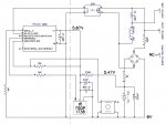
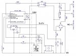
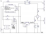
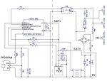
Proposed circuit is shown below. The components to the right of the vertical dashed line are existing with the exception of the SSR which is currently a triac. The SSR proposed is a zero cross switching AC to 380V with a 3-15VDC control so can be driven direct from the 08M.
Obviously space is at a premium which is the only reason the existing DC supply being derived from the AC Mains is being retained. It is possible that once assembled the DC voltage may be too high so would appreciate suggestions on the best way to adjust that (change the 1M and/or 330R value?).
Any other constructive suggestions appreciated.
Thanks
Have two remote light switches which do not work properly in that the switch requires repeat activation to get the light to turn on. The light usually flashes momentarily for each activation and will only stay on after repeat activation - any number from 1 to 8 or so.
These are commercial products for which I have found no alternative. We have two of these switches and they both act the same. We have had them replaced (twice) under warranty but all 6 switches behave the same.
Have decided to re-engineer with a Picaxe and SSR to replace the Triac and array of diodes, transistors, dual flipflop and hex inverter chips that are currently employed to provide the latch and the signal to the the triac trigger.
The revised circuit will be installed inside the existing box which fits into a standard wall box on a standard faceplate.
Proposed circuit is shown below. The components to the right of the vertical dashed line are existing with the exception of the SSR which is currently a triac. The SSR proposed is a zero cross switching AC to 380V with a 3-15VDC control so can be driven direct from the 08M.
Obviously space is at a premium which is the only reason the existing DC supply being derived from the AC Mains is being retained. It is possible that once assembled the DC voltage may be too high so would appreciate suggestions on the best way to adjust that (change the 1M and/or 330R value?).
Any other constructive suggestions appreciated.
Thanks
Attachments
-
 43.6 KB Views: 118
Last edited:
")