Pinewood Derby Stopwatch/Timer

Rick100

Senior Member
Hello Al,
Just a few quick questions. Do you have pullup resistors on any unused inputs? Do you get the START RACE message on the terminal window indicating the 'pushed' branch was taken?

Code:
pushed:high C.0: high C.1: high C.6  ; output on
outpinsC = outpinsC | %01000011
Do you mean to set bit 6 or 2 on port C? The 2 lines also seem redundant.

You also refer to C.6 in this line.
Code:
if bit0 = 1 then LOW C.6		;IR beam broken on Lane 3
endif
Good luck,
Rick
 
Last edited:

Goeytex

Senior Member
The phototransistor will need to supply ~ 2.8ma of current to drop 5v across the 1.8K resistor R3. This current depends upon the amount of light reaching the transistor. 1.8K seems too small to me. I would suggest 4.7K or 10K for R3,R4,R5. The higher value means less light needed to toggle the hex inverter.

I would suggest simplifying the code for hardware troubleshooting. First eliminate the hardware as the problem. Then debug the code if the problem persists.


Example code snippet to test the Photo transistor circuitry: If this works, then code is the problem, if not then troubleshoot the hardware

Code:
#picaxe 18M2
#com 3
#terminal 38400
setfreq m32

input B.1
pause 2000

do
   if pinB.1 = 1 then
     sertxd ("Pin B.1 is  High",cr,lf)
   else if Pinb.1 = 0 then
     sertxd ("Pin B.1 is Low",cr,lf)
   endif

   Pause 1000  

loop
 
Last edited:

vttom

Senior Member
Fist off, like Rick100 says above, these 2 lines are redundant...

Code:
pushed: high C.0: high C.1: high C.6  ; output on
outpinsC = outpinsC | %01000011
Furthermore, according to manual 1, the "outpins" variable is intended to be used on the left side of the equals sign, not the right. By using it on the right, you may be inadvertently changing all of the port C pin directions from output to input.

You should delete the second line and see if that improves things.

Also, there is a pin C.2 vs. pin C.6 discrepancy in your schematic vs. the program.

As for port B... You are using it as an input port, but you don't set the pin directions in software. Theoretically they are supposed to be inputs by default, but why leave that to chance?

Also, even though you are masking off the unused inputs on port B, they are floating in hardware. Floating inputs can, at the very least, cause the PICAXE to draw a lot of power. You should either change the pin directions on the unused port B pins to output, or tie them high or low with resistors in the circuit (you don't want to tie them directly to GND or VDD because you could destroy the pin drivers if the software accidentally turns them into outputs).
 
Last edited:

AlbertZ

Senior Member
“Also, there is a pin C.2 vs. pin C.6 discrepancy in your schematic vs. the program.”Thank you, yes. I changed C.6 to C.2 in order to clean up the PCB layout but completely forgot to change the software. It’s been corrected.

“Furthermore, according to manual 1, the "outpins" variable is intended to be used on the left side of the equals sign, not the right. By using it on the right, you may be inadvertently changing all of the port C pin directions from output to input.

You should delete the second line and see if that improves things.”
Good point, I rem’d it out for the time being.

“Do you get the START RACE message on the terminal window indicating the 'pushed' branch was taken?”
Yes

“Do you have pullup resistors on any unused inputs?”
No, but I will change all unused B ports to outputs in the software.

“I would suggest simplifying the code for hardware troubleshooting. First eliminate the hardware as the problem. Then debug the code if the problem persists.”
We pretty much went through the hardware and everything seems to be working fine. Easy to verify with scope and multimeter. Things fall apart when the PICAXE is introduced into the circuit, can’t get past starting the race by tripping the limit switch.

More later after I had time to evaluate and implement suggestions. Thanks to all for your input!

Al
 

Rick100

Senior Member
Thank you, yes. I changed C.6 to C.2 in order to clean up the PCB layout but completely forgot to change the software. It’s been corrected.
I've done that several times.
“Do you get the START RACE message on the terminal window indicating the 'pushed' branch was taken?”
Yes
The Start Race Message is a very good sign.
“Do you have pullup resistors on any unused inputs?”
No, but I will change all unused B ports to outputs in the software.
You can also use the pullup command 'pullup ON' or 'pullup' with a mask value to enable the internal weak pullup resistors.

The following change in your code on the line following the 'myloop' label will print out the state of portB inputs every time through the main loop. This will make it easier to tell what's going on. In the line 'b0 = pinsB & %00001011' , the '& %00001011' is not necessary since you check each bit individually.

Code:
'b0 = pinsB & %00001011		;mask off bits 0, 1 & 3
b0 = pinsB
sertxd("portB = ",#bit7,#bit6,#bit5,#bit4,#bit3,#bit2,#bit1,#bit0,13,10)
Good luck,
Rick
 

AlbertZ

Senior Member
Well, I had to deal with a couple of issues before getting back to the heart of the matter. One of my breadboards developed a short and had to be replaced. I guess that is better than a breadboard in your shorts. Also I had to ditch the XINO shield which developed an intermittent and was a pain in the butt to attach wires to.

First I made the software changes everyone suggested – here is the revised code:
Code:
'=======================PinewoodDerby.bas===========================

'===constants===

'===variables===


Symbol Q_3 = B.0		; rename input B.0 ‘Q_3’
Symbol Q_1 = B.1		; rename input B.1 ‘Q_1’
Symbol SW_1 = B.2		; rename input B.2 ‘SW_1’
Symbol Q_2 = B.3		; rename input B.3 ‘Q_2’
Symbol Ln_2 = C.0		; rename output C.0 ‘Ln_2’
Symbol Ln_1 = C.1		; rename output C.1 ‘Ln_1’
Symbol Ln_3 = C.2		; rename output C.2 ‘Ln_3’


'===directives===
'#com3						'specify serial port
#picaxe 18M2				'specify processor
#no_data					'save download time
'#terminal of				'disable terminal window

'=======================begin main program===========================

setfreq M32					'run program at max speed

let dirsC=%11111111				'all outputs

let dirsB=%11110000				'change bits 7,6,5, & 4 to 									'outputs

pwmout pwmdiv64, B.6, 124, 250 	'produces a 1 kHz square wave
						'output on pin B.6

init: b2 = 0 				; reset targetbyte
						; before the loop
; input B.2, active high, jump to ‘pushed’ label when = 1
myloop: button SW_1,1,200,100,b2,1,pushed

b0 = pinsB & %00001011		;mask off bits 0, 1 & 3


if bit1 = 1 then LOW C.1		;IR beam broken on Lane 1
endif	

if bit3 = 1 then LOW C.0		;IR beam broken on Lane 2
endif	
	
if bit0 = 1 then LOW C.2		;IR beam broken on Lane 3
endif	
	
goto myloop
	
pushed: high C.0: high C.1: high C.2  ; output on
;outpinsC = outpinsC | %00000111
sertxd ("START RACE") ; send push message
goto myloop
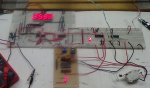
Since I’m not using them in the breadboard configuration, I ran B.0 and B.3 to ground through a couple of 10k resistors. I also had to re-wire the phototransistor to the appropriate pins (3 & 4) on U2 hex inverter.

I powered the board up and nothing happened until I tripped the limit switch, then it immediately started counting. Eureka!

Now for the acid test; I broke the IR beam expecting the count to stop -- and it did not. Whiskey Tango Foxtrot!

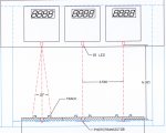
Definitely getting a Hi/Lo signal from the Schmidt trigger every time the beam is interrupted. B.1 stays Lo until the beam is interrupted, and goes Hi whenever I break the beam. The phototransistor is doing exactly what it is supposed to do, however C.2 is staying Hi all the time. The 18M2 should be driving C.2 Lo whenever B.1 goes Hi.

C.2 is the control signal which opens and closes the CD4066 gate allowing pulses to go to the display. I did ground pins 5, 12 & 13 of the CD4066.

When the beam is broken, C.2 should go Lo and stay there until the 18M2 is reset, even after the car passes by the beam. We don’t want the display to start counting again after the car has passed by. This brings up another issue. We made no provision for resetting the system.

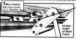
My thought was to use the N.C. contact of the limit switch. The race starts by closing the limit switch and pulling Pin 1 of the 74LS14 Lo. Now the limit switch stays closed for the entire duration of the race. It only opens up again when the starting gate is positioned for the next race. The N.C. contact could be wired to one of the unused input pins on the 18M2. This pin would stay Hi until the race started when it would go Lo and stay there for the entire race. When the starting gate was positioned for the next race, the pin would go high again, thus resetting the system.

So that begs three questions:
1. Can anyone suggest an issue with the code that is preventing C.2 from going Lo?
2. Is there a possibility of a wiring error that I am somehow overlooking?
3. Can anyone suggest a snippet of code that would implement a reset function?

Thanks
Al

DSC00077.JPG
 

Rick100

Senior Member
The 18M2 should be driving C.2 Lo whenever B.1 goes Hi.
Code:
if bit1 = 1 then LOW C.1		;IR beam broken on Lane 1
endif	

if bit3 = 1 then LOW C.0		;IR beam broken on Lane 2
endif	
	
if bit0 = 1 then LOW C.2		;IR beam broken on Lane 3
endif
Your code checks B.0 for a high to clear C.2.

3. Can anyone suggest a snippet of code that would implement a reset function?
You can restructure your code and use an output from the picaxe to reset the displays after the limit switch opens.


Good luck
Rick
 
Last edited:

AlbertZ

Senior Member
“Your code checks B.0 for a high to clear C.2”

Yes, that’s what we want to happen. B.1 goes high, C.2 goes low. It works on the simulator! What am I missing here?


Al
 

Rick100

Senior Member
“Your code checks B.0 for a high to clear C.2”

Yes, that’s what we want to happen. B.1 goes high, C.2 goes low. It works on the simulator! What am I missing here?


Al
Change
Code:
if bit1 = 1 then LOW C.1		;IR beam broken on Lane 1
endif
to
Code:
if bit1 = 1 then LOW C.2		;IR beam broken on Lane 1
endif
Unless I'm confused, which wouldn't be the first time. :confused:
 

Goeytex

Senior Member
When defining symbols for inputs it needs to be in the form of PinPortx

Change the input symbols to:
Code:
Symbol Q_3 =[COLOR="#B22222"] PinB.0[/COLOR]		; rename input B.0 ‘Q_3’
Symbol Q_1 = [COLOR="#B22222"]PinB.1[/COLOR]		; rename input B.1 ‘Q_1’
Symbol SW_1 = [COLOR="#B22222"]PinB.2[/COLOR]		; rename input B.2 ‘SW_1’
Symbol Q_2 =[COLOR="#B22222"] PinB.3	[/COLOR]	; rename input B.3 ‘Q_2’
EDIT:
With the syntax corrected above. The button command needs to use "B.2" instead of "SW_1".
 
Last edited:

vttom

Senior Member
If I'm reading your schematic correctly, the port B/C input/output correspondence is:

Lane 1 : B.1 / C.2
Lane 2 : B.3 / C.1
Lane 3 : B.0 / C.0

So your if statements are all wrong. They should look like:

Code:
if bit1 = 1 then low c.2 : endif
if bit3 = 1 then low c.1 : endif
if bit0 = 1 then low c.0 : endif
 

AlbertZ

Senior Member
Change
Code:
if bit1 = 1 then LOW C.1		;IR beam broken on Lane 1
endif
to
Code:
if bit1 = 1 then LOW C.2		;IR beam broken on Lane 1
endif
Unless I'm confused, which wouldn't be the first time. :confused:
Duh! It was as plain as the nose on my face. This is a clear case of not seeing the forest for the trees.
 

AlbertZ

Senior Member
When defining symbols for inputs it needs to be in the form of PinPortx

Change the input symbols to:
Code:
Symbol Q_3 =[COLOR="#B22222"] PinB.0[/COLOR]		; rename input B.0 ‘Q_3’
Symbol Q_1 = [COLOR="#B22222"]PinB.1[/COLOR]		; rename input B.1 ‘Q_1’
Symbol SW_1 = [COLOR="#B22222"]PinB.2[/COLOR]		; rename input B.2 ‘SW_1’
Symbol Q_2 =[COLOR="#B22222"] PinB.3	[/COLOR]	; rename input B.3 ‘Q_2’
EDIT:
With the syntax corrected above. The button command needs to use "B.2" instead of "SW_1".
Shouldn't this convention apply to the output pins as well?
 

AlbertZ

Senior Member
If I'm reading your schematic correctly, the port B/C input/output correspondence is:

Lane 1 : B.1 / C.2
Lane 2 : B.3 / C.1
Lane 3 : B.0 / C.0

So your if statements are all wrong. They should look like:

Code:
if bit1 = 1 then low c.2 : endif
if bit3 = 1 then low c.1 : endif
if bit0 = 1 then low c.0 : endif
Thanks vttom, the light bulb finally came on.
 

Goeytex

Senior Member
Shouldn't this convention apply to the output pins as well?
It does not. See manual 2 Page 27

Example: If PinB.1 = 1 then ........ reads the input pin

If B.1 = 1 does not

PinC.X are variables that can be either 1 or 0

B.0 - b.7 and C.0 - C.7 are constants from 0 -15 that represent the logical pin numbers.
 
Last edited:

AlbertZ

Senior Member
It does not. See manual 2 Page 27

Example: If PinB.1 = 1 then ........ reads the input pin

If B.1 = 1 does not

PinC.X are variables that can be either 1 or 0

B.0 - b.7 and C.0 - C.7 are constants from 0 -15 that represent the logical pin numbers.
Thanks. It's quite obvious I have a lot to learn.

Al
 

AlbertZ

Senior Member
Success at Last!!

Well I made the changes as suggested and I am very pleased to say that the circuit works the way I originally intended. When the limit switch is pulsed, the counter begins. When the beam is interrupted (even for a few milliseconds) the count stops. B.1 goes high and stays high when SW is toggled. When the beam is interrupted, B.1 goes low and stays low. I am a very happy camper.
:D

Code:
'=======================PinewoodDerby.bas======================
'===Version 4.0===

'===constants===

'===variables===


Symbol Q_3 = PinB.0		; rename input B.0 'Q_3'
Symbol Q_1 = PinB.1		; rename input B.1 'Q_1'
Symbol SW_1 = PinB.2		; rename input B.2 'SW_1'
Symbol Q_2 = PinB.3		; rename input B.3 'Q_2'
Symbol Ln_2 = C.0		; rename output C.0 ?Ln_2?
Symbol Ln_1 = C.1		; rename output C.1 ?Ln_1?
Symbol Ln_3 = C.2		; rename output C.2 ?Ln_3?


'===directives===
'#com3						'specify serial port
#picaxe 18M2				'specify processor
#no_data					'save download time
'#terminal of				'disable terminal window

'===================begin main program========================

setfreq M32					'run program at max speed

let dirsC=%11111111				'all outputs

let dirsB=%10110000				'change bits 7,5, & 4 to outputs

pwmout pwmdiv64, B.6, 124, 250 	'produces a 1 kHz square wave
						'output on pin B.6

init: b2 = 0 				; reset targetbyte
						; before the loop
; input B.2, active high, jump to ?pushed? label when = 1

myloop: button B.2,1,200,100,b2,1,pushed

b0 = pinsB & %00001011		;mask off bits 0, 1 & 3


if bit1 = 1 then LOW C.2		;IR beam broken on Lane 1
endif	

if bit3 = 1 then LOW C.1		;IR beam broken on Lane 2
endif	
	
if bit0 = 1 then LOW C.0		;IR beam broken on Lane 3
endif	

if b2=0 then goto init		;resets for the next race
	
goto myloop
	
pushed: high C.0: high C.1: high C.2  ; output on
;outpinsC = outpinsC | %00000111
sertxd ("START RACE") ; send push message
goto myloop


However there is one anomaly. As long as B.2 stays high (limit switch is closed), the counter will not shut off. The counter slows down while the beam is interrupted and continues as soon as the beam is cleared. I can see no reason why this should be so. Is it a hardware or software issue? Inquiring minds want to know. It looks like a lot of noise going back to the display driver. Doesn’t do this in the simulator, so I’ll have to take a different approach to reset.

I also want to add my heartfelt thanks to everyone who contributed to this thread. I couldn't have done it without you guys. This is a great forum!:)

Al
Washington, PA
 

Rick100

Senior Member
Hello Al,
Looks like your making progress.
The line
Code:
if b2=0 then goto init		;resets for the next race
should probably be
Code:
if pinB.2=0 then goto init		;resets for the next race
Your checking your button work variable instead of the start switch.

Good luck,
Rick
 

Rick100

Senior Member
Hello again Al,
I think the button command's auto-repeat feature is also giving you problems.
Code:
myloop: button B.2,1,200,100,b2,1,pushed
If you run the simulation at full speed instead of stepping through the code, you can see it jumps to the pushed label, restarting your counters, after 200 times through the main loop. It then jumps to the pushed label every 100 times through the main loop.
To see it in the simulator, click on the line number to the left of the 'pushed: high C.0: high C.1: high C.2' line to set a breakpoint. Then select 'RUN' from the simulation menu. When the simulation starts click the B.2 pin to set it. The simulation will then stop at the breakpoint. Click the 'RUN" button several times until it starts running again. You can then watch variable b2 decrement down to zero which will cause the jump to the myloop label.
This would explain your slowly incrementing counter. Try changing it to
Code:
myloop: button B.2,1,255,100,b2,1,pushed
According to the manual that will give you a debounce without auto-repeat. That may fix your problem but I think it would be best to restructure your program to use an 'IF THEN' statement instead of the button command.

Good luck'
Rick
 
Last edited:

vttom

Senior Member
One way to work around your problem would be to introduce a new input switch. One that is manually operated and used to move your "state machine" from waiting for the cars to finish to waiting for the start of the race, eg.


Code:
wait_for_start:

' Wait for a low-to-high transition on SW_1
do : loop until SW_1 = 0
do : loop until SW_1 = 1

high C.0
high C.1
high C.2
sertxd ("START RACE")

wait_for_finish:

b0 = pinsB

if bit1 = 1 then low c.2 : endif
if bit3 = 1 then low c.1 : endif
if bit0 = 1 then low c.0 : endif

if some_other_input = 1 then goto wait_for_start

goto wait_for_finish
 

AlbertZ

Senior Member
One way to work around your problem would be to introduce a new input switch. One that is manually operated and used to move your "state machine" from waiting for the cars to finish to waiting for the start of the race, eg.


Code:
wait_for_start:

' Wait for a low-to-high transition on SW_1
do : loop until SW_1 = 0
do : loop until SW_1 = 1

high C.0
high C.1
high C.2
sertxd ("START RACE")

wait_for_finish:

b0 = pinsB

if bit1 = 1 then low c.2 : endif
if bit3 = 1 then low c.1 : endif
if bit0 = 1 then low c.0 : endif

if some_other_input = 1 then goto wait_for_start

goto wait_for_finish
Thanks vttom

That is certainly a possibility. However I would like to exhaust other avenues before pursuing that route. I still think we can make this work with only one limit switch. I want to use the existing track configuration to keep things simple for those who will be using the system after I am no longer involved with the scouts.

As presently configured, the track is designed for the addition of a start limit switch which stays closed during the race and opens when the gate goes up and the cars are staged for the next race. The attached picture explains it better than I can.

Al

Limit Switch Mounting.jpg
 

vttom

Senior Member
So you're saying once the switch closes, it stays closed until the race has concluded and the scores have been recorded? If that's the case, then the logic does become much simpler...

Code:
ready_set:

do : loop until SW_1 = 0

sertxd ("READY, SET, ")

do : loop until SW_1 = 1

high C.0
high C.1
high C.2

sertxd ("GO!")

' Slight pause to debounce SW_1
pause 10

do

  b0 = pinsB

  if bit1 = 1 then low c.2 : endif
  if bit3 = 1 then low c.1 : endif
  if bit0 = 1 then low c.0 : endif

loop until SW_1 = 0

goto ready_set
 

AlbertZ

Senior Member
Hello again Al,
I think the button command's auto-repeat feature is also giving you problems.
Code:
myloop: button B.2,1,200,100,b2,1,pushed
If you run the simulation at full speed instead of stepping through the code, you can see it jumps to the pushed label, restarting your counters, after 200 times through the main loop. It then jumps to the pushed label every 100 times through the main loop.
To see it in the simulator, click on the line number to the left of the 'pushed: high C.0: high C.1: high C.2' line to set a breakpoint. Then select 'RUN' from the simulation menu. When the simulation starts click the B.2 pin to set it. The simulation will then stop at the breakpoint. Click the 'RUN" button several times until it starts running again. You can then watch variable b2 decrement down to zero which will cause the jump to the myloop label.
This would explain your slowly incrementing counter. Try changing it to
Code:
myloop: button B.2,1,255,100,b2,1,pushed
According to the manual that will give you a debounce without auto-repeat. That may fix your problem but I think it would be best to restructure your program to use an 'IF THEN' statement instead of the button command.

Good luck'
Rick
Hi Rick

Yes I agree that we really don't need a button command for this application for two reasons:

1. The 'limit switch' stays in the closed position from the start of the race until it is reset for the next race.
2. We don't need to de-bounce the input. That is taken care of with an RC timer & Schmidt trigger in the circuit.

So I got rid of the button command and added a little routine I called "main". This is where the program just sits and waits for the next switch closure. I tested it on the simulator and on the breadboard. Seems to work perfectly!!! WooHoo!!!:eek:

Here is the revised code:

Code:
'=======================PinewoodDerby.bas======================
'===Version 4.1===

'===constants===

'===variables===


Symbol Q_3 = PinB.0		; rename input B.0 'Q_3'
Symbol Q_1 = PinB.1		; rename input B.1 'Q_1'
Symbol SW_1 = PinB.2		; rename input B.2 'SW_1'
Symbol Q_2 = PinB.3		; rename input B.3 'Q_2'
Symbol Ln_2 = C.0		; rename output C.0 ?Ln_2?
Symbol Ln_1 = C.1		; rename output C.1 ?Ln_1?
Symbol Ln_3 = C.2		; rename output C.2 ?Ln_3?


'===directives===
'#com3						'specify serial port
#picaxe 18M2				'specify processor
#no_data					'save download time
'#terminal of				'disable terminal window

'===================begin main program========================

setfreq M32					'run program at max speed

let dirsC=%11111111				'all outputs

let dirsB=%10110000				'change bits 7,5, & 4 to outputs

pwmout pwmdiv64, B.6, 124, 250 	'produces a 1 kHz square wave
						'output on pin B.6

;init: b2 = 0 				; reset targetbyte
						; before the loop

main:

if pinB.2 = 1 then goto start    	;limit switch closed to start race

goto main


myloop:

b0 = pinsB & %00001011		;mask off bits 0, 1 & 3

if bit1 = 1 then LOW C.2		;IR beam broken on Lane 1
endif	

if bit3 = 1 then LOW C.1		;IR beam broken on Lane 2
endif	
	
if bit0 = 1 then LOW C.0		;IR beam broken on Lane 3
endif	

if pinB.2 = 0 then goto main		;resets for the next race
	
goto myloop
	
start:
high C.0: high C.1: high C.2  ; output on

sertxd ("START RACE") ; send push message
goto myloop
And here is a video of the successful test:

http://www.youtube.com/watch?v=nOncR6NBDAQ&feature=youtu.be

Again, thanks to everyone for their input without which none of this would have been possible. It's time to start etching some circuit boards.

Rick, do you have any thoughts on uploading the data to a PC?

Al
 

Rick100

Senior Member
Hello Al,

Looks like your getting there. I enjoyed the video.
Rick, do you have any thoughts on uploading the data to a PC?
Yes I do but, they are a little involved. By data, I assume you mean the times for each car. My ideas are only based on reading the 74c926 data sheet, and I could be missing some detail that would stop this from working.

First you have to get the times out of the 74c926 and into the picaxe after the race is complete. I think you can do this by:

Turn off hardware PWM so we can send pulses under sofware control.
Enable a 4066 gate for the 74c926 your trying to read.
Pulse the clock line, keeping count of the pulses, until you detect a high to low transition on the carry out pin.
The count in the picaxe could be subtracted from 10000 to get the count in the 74c926.
Then you could send it to the PC.

I think you could use the display select and latch enable lines to keep the original count on the display while your doing this. You would need to do some experimenting to see if all this would work. As I said, this is a little involved. Since your getting ready to make your boards, you could bring all the 74c926 control lines out to a header for trying this in the future. You will need a higher pin count picaxe like the 28X2 to control all the features of the 74c926. If you didn't care about seeing the display count changing while you clocked it, you might be able to do it with an 18M2.

I noticed in your video you have a manual reset. You could probably do this with an output pin from the picaxe. I also noticed in your schematic, you have the Cout signal tied to 5V . Since it is an output, I don't think that's right.

Good luck,
Rick
 
Last edited:

AlbertZ

Senior Member
Hello Al,

Looks like your getting there. I enjoyed the video.


Yes I do but, they are a little involved. By data, I assume you mean the times for each car. My ideas are only based on reading the 74c926 data sheet, and I could be missing some detail that would stop this from working.

First you have to get the times out of the 74c926 and into the picaxe after the race is complete. I think you can do this by:

Turn off hardware PWM so we can send pulses under sofware control.
Enable a 4066 gate for the 74c926 your trying to read.
Pulse the clock line, keeping count of the pulses, until you detect a high to low transition on the carry out pin.
The count in the picaxe could be subtracted from 10000 to get the count in the 74c926.
Then you could send it to the PC.

I think you could use the display select and latch enable lines to keep the original count on the display while your doing this. You would need to do some experimenting to see if all this would work. As I said, this is a little involved. Since your getting ready to make your boards, you could bring all the 74c926 control lines out to a header for trying this in the future. You will need a higher pin count picaxe like the 28X2 to control all the features of the 74c926. If you didn't care about seeing the display count changing while you clocked it, you might be able to do it with an 18M2.

I noticed in your video you have a manual reset. You could probably do this with an output pin from the picaxe. I also noticed in your schematic, you have the Cout signal tied to 5V . Since it is an output, I don't think that's right.

Good luck,
Rick
Hi Rick

You were right when you said a little involved. I think I'll leave outputting to a PC for another project, perhaps using a MAX7219 & MAX 232. Maybe next year.

Good catch on the Carryout. I don't think we would have caught this if not for the output to PC discussion. At any rate, I changed the schematic and PCB layout. With that said it doesn't appear to have harmed the chip. I had it connected to +5v on the breadboard without any apparent ill effects.

I'm going to keep a manual reset on the display for the time being. This will prevent an inadvertent clear while the race stewards are recording the results.

Early on we had a discussion about alignment of the IR source and phototransistors. Well, no worries mate! The sources and phototransistors are pre-aligned in a framework which houses the displays. The sources are mounted on the display PCB. Every time the track is set up for a race, all one has to do is slip the track inside the frame until the holes in the track line up with the LEDs. Voila! You’re good to go! What makes this system work is choosing the correct IR emitter and phototransistor for the application. I chose components that were matched for a peak wavelength of 940 nm. This keeps us well out of the range of typical fluorescent lighting wavelengths which are well below 800 nm. For my source LED I settled on the LTE-2872U. This has a peak wavelength of 940 nm and a very narrow bandwidth of 900-980 nm. It has a narrow 16 degree beam which projects to a 1 inch diameter circle at a distance of 6 inches. The output power is a healthy 53 mW/sr @100 mA.

http://optoelectronics.liteon.com/upload/download/DS-50-93-0018/P_100_E2872U.pdf

For the detector I finally settled on the Vishay TEFT4300. It is in a T-1 package (the smaller the sensor, the greater the accuracy) with daylight blocking filter matched with 940 nm emitters. Rise and fall times are 2 usec.

http://www.vishay.com/docs/81549/teft4300.pdf

I couldn't be happier with the system. It is virtually immune to all extraneous indoor light.

Thanks

Al

Pinewood Derby Bridge.JPG
 

AlbertZ

Senior Member
Yeah, it's not an elegant solution. What method do you use to make your boards? I use Eagle for the schematic and pcb layout, and the toner transfer method.

Good luck,
Rick
I've been using Express PCB and the toner transfer method, Eagle is looks like great gear for the professional designer but it's just too clutzy for my purposes.

I have just found a source in China for really cheap pre-sensitized boards so for this project I'm going to try exposing the board with a UV box. I just ordered 100 UV LED's and I will be putting this together shortly. Unfortunately, we have been experiencing sub-zero (F) temperatures and all my woodworking gear is in the garage. So I am a couple of weeks away from getting the wood cut. I'll keep you posted on how it works out.

Al
 

AlbertZ

Senior Member
Well, I've gone from breadboard to PCB and worked up a prototype to demonstrate the viability of this project. It is set up on my Grandson's 2-lane "hot wheels" track. The final version required some capacitors and pull down resistors to stabilize the displays and what you see in the video is the final result. The display readout is in milliseconds.

Phase two will consist of an order of finish display. I have worked out the circuitry and code. It will use a 14M2 as a co-processor to drive the display.

http://youtu.be/ETBvTs5ptX8

Al
 
Top