Pinewood Derby Stopwatch/Timer

AlbertZ

Senior Member
Yes - the Picaxe may well be running at 32MHz - but is doing lots of things - so it may well be only ready to start polling every 1,000 or so clock cycles - so the system may well be missing a lot!

The main thing is to make it repeatable - so each reading is as accurate/inaccurate as any other - which actually gives you accurate differences between readings :confused:
Hmm – doing what other things? Inquiring minds want to know. Is there a way to calculate roughly what the processing time would be?

Be that as it may, let us accept for discussion purposes that the processor is poling the transistors every 1000 or so clock cycles. That still means that they are being poled roughly 32 times each millisecond. So in theory we could register a “hit” on the first clock cycle or the 32nd clock cycle in the first millisecond of the beam interruption. This would generate a repeatability error of 3.2% in the first millisecond. Translated into practical terms, this could mean the difference between 3.005 seconds and 3.006 seconds in the race result.

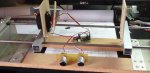
It seems to me that the alignment and positioning of the IR LEDs and the photo-transistors becomes the critical factor in determining the “fairness” of each race, as well as other factors external to the processor.
We can certainly agree that the ability to precisely measure the time duration of each race is secondary to the ability of the system to provide the same measure of accuracy from the first race of the day to the last.

The bottom line is this – until I assemble some hardware and begin testing, this is all speculation. One thing is for sure, I’m learning an awful lot and this was one of my goals when I began this project. Thanks to all who have contributed to the discussion!
 

Rick100

Senior Member
Hmm – doing what other things? Inquiring minds want to know. Is there a way to calculate roughly what the processing time would be?
Hell Albert. Even a pic with a 32 MHz clock running native pic instructions in assembly language , would only be executing 8 million instructions per second . From the datasheet:
'One instruction cycle consists of 4 oscillator cycles; for an oscillator frequency of 4 MHz, this gives a nominal instruction execution rate of 1 MHz.'

The 'other things' the picaxe is doing , is running the basic interpreter. The basic interpreter is made up of the native pic instructions. You basic program is data that the interpreter parses and executes. Here is a link to info on the speed and structure of the picaxe instructions. The info is in the pdf files.
http://www.picaxeforum.co.uk/showthread.php?17782-PICAXE-program-Size-Optimisations-and-Speed


Be that as it may, let us accept for discussion purposes that the processor is poling the transistors every 1000 or so clock cycles. That still means that they are being poled roughly 32 times each millisecond. So in theory we could register a “hit” on the first clock cycle or the 32nd clock cycle in the first millisecond of the beam interruption. This would generate a repeatability error of 3.2% in the first millisecond. Translated into practical terms, this could mean the difference between 3.005 seconds and 3.006 seconds in the race result.
How many times a second you can poll the inputs per second , will depend on the number and type of instructions in your polling loop.
After some changes to the program I posted above , I still get an ocassional 1 millisecond of jitter. It only polls the inputs once per millisecond.

Good luck,
Rick
 

AllyCat

Senior Member
Hi,

Hmm – doing what other things? Inquiring minds want to know. Is there a way to calculate roughly what the processing time would be?
Yes, there's a lot of information in this thread. The "early" information is a little dated now, the M2s are actually slower (for a given clock speed) because the instruction set and address space are larger. I've quoted some typical execution times for M2s (and a method of measuring them) on the second page, but my rule of thumb is that the PICaxe interpreted instructions execute about 300 times slower than compiled code.

But with good program structure you should be able to resolve to about 1ms. The important factor is to ensure that the program code is "fair". For example you should check all the lanes within a particular "time frame" before declaring a winner (or a dead heat if which was the first event cannot be resolved).

Cheers, Alan.
 

techElder

Well-known member
Offering a clue ... if your resolution is 1mSec, and you display three digits after the decimal point, then you better not "call" a tie (because you calculated timing tolerance) if the last digits display different numbers. The kids won't care so much, but you might just be wary of the parents.

Just trying to help you out, Bud. ;)
 

AlbertZ

Senior Member
Hell Albert. Even a pic with a 32 MHz clock running native pic instructions in assembly language , would only be executing 8 million instructions per second . From the datasheet:
'One instruction cycle consists of 4 oscillator cycles; for an oscillator frequency of 4 MHz, this gives a nominal instruction execution rate of 1 MHz.'

The 'other things' the picaxe is doing , is running the basic interpreter. The basic interpreter is made up of the native pic instructions. You basic program is data that the interpreter parses and executes. Here is a link to info on the speed and structure of the picaxe instructions. The info is in the pdf files.
http://www.picaxeforum.co.uk/showthr...ions-and-Speed
Thanks Rick! That puts things into much better perspective as well as providing a deeper understanding of the limits and capabilities of the PICAXE system.

How many times a second you can poll the inputs per second , will depend on the number and type of instructions in your polling loop.
After some changes to the program I posted above , I still get an ocassional 1 millisecond of jitter. It only polls the inputs once per millisecond.
What it all comes down to is that poling the inputs every msec is the bottom line number, so lets work with this. Then it seems to me that the error (in case of a tie) is .001 seconds.
 

AlbertZ

Senior Member
Hi,

Yes, there's a lot of information in this thread. The "early" information is a little dated now, the M2s are actually slower (for a given clock speed) because the instruction set and address space are larger. I've quoted some typical execution times for M2s (and a method of measuring them) on the second page, but my rule of thumb is that the PICaxe interpreted instructions execute about 300 times slower than compiled code.

But with good program structure you should be able to resolve to about 1ms. The important factor is to ensure that the program code is "fair". For example you should check all the lanes within a particular "time frame" before declaring a winner (or a dead heat if which was the first event cannot be resolved).

Cheers, Alan.

Thanks Alan. If I am interpreting the information provided by Rick and confirmed by yourself, the “time frame” within which we are checking all the lanes is once per msec. (“ It only polls the inputs once per millisecond”).
 

AlbertZ

Senior Member
Offering a clue ... if your resolution is 1mSec, and you display three digits after the decimal point, then you better not "call" a tie (because you calculated timing tolerance) if the last digits display different numbers. The kids won't care so much, but you might just be wary of the parents.

Just trying to help you out, Bud. ;)

Hey Texas, how are you?
Allow me to put things in a bit of historical perspective. The Pinewood Derby track used by the local Cub Scout packs is aluminum utilizing 4 lanes. At one time it was fitted with some sort of electronic timing device which is no longer operative. We tried a go at repairing it, but without documentation this proved to be unsuccessful. (It used limit switches and TTL logic to determine finish)

So here is what we did last year. First we only raced in two lanes. We had a parent stand on each side of the track with a stop watch. The start of the race was indicated by a limit switch actuated light. We would start the stop watches and then watch the cars cross the finish line. In the event of a too close to call we compared our stop watches. If the stop watches did not agree, we ran the race again. As you can imagine, the process was quite tedious. Now consider the fact that we had to run three heats to determine the winner, then the winners of the three heats raced against each other for three heats, etc. – well, you get the idea.

My purpose in initiating this project was to speed up the process and provide an objective number to compare results, rather than a subjective eyeball clicking a manual stop watch. Kids winning at the pack level go on to compete in regional contests where the equipment is far more sophisticated and displays times to .0001 second. At the regional level, where the competition is much more intense, all the race data is tabulated and fed into a PC. This is far beyond what is required at the pack level where the objective is to have fun and display good sportsmanship.
 

techElder

Well-known member
I applaud you for getting involved at this level. I've done the same in various venues over many years, so I know what it takes. You definitely have what it takes.

My purpose for commenting was not to be discouraging, and I'm glad to see that you didn't take it that way.

I'm just saying that once you put those "3-digit accurate" displays out there for all to see, you have moved everyone to a different level. The perception of precision has let the genie out of the bottle. So, be prepared to let the display decide who the winner is and provide no more knowledge than is minimally necessary.

For example, in a competition/club that I'm involved in, they use "3-digit accurate" timers to determine winners and to compare winners from year to year. The timing is in the 300 mSec range and many pairings are decided with only 1 mSec difference. I happen to know that the timers they use have variations greater than 1 mSec from environmental changes (such as the difference between summer and winter temps.) Do I say anything? Hell no! Everyone goes about their merry ways with no one considering the consequences ... but me. :)

My purpose in initiating this project was to speed up the process and provide an objective number to compare results, rather than a subjective eyeball clicking a manual stop watch. Kids winning at the pack level go on to compete in regional contests where the equipment is far more sophisticated and displays times to .0001 second. At the regional level, where the competition is much more intense, all the race data is tabulated and fed into a PC. This is far beyond what is required at the pack level where the objective is to have fun and display good sportsmanship.
 

AlbertZ

Senior Member
I applaud you for getting involved at this level. I've done the same in various venues over many years, so I know what it takes. You definitely have what it takes.

My purpose for commenting was not to be discouraging, and I'm glad to see that you didn't take it that way.

I'm just saying that once you put those "3-digit accurate" displays out there for all to see, you have moved everyone to a different level. The perception of precision has let the genie out of the bottle. So, be prepared to let the display decide who the winner is and provide no more knowledge than is minimally necessary.

For example, in a competition/club that I'm involved in, they use "3-digit accurate" timers to determine winners and to compare winners from year to year. The timing is in the 300 mSec range and many pairings are decided with only 1 mSec difference. I happen to know that the timers they use have variations greater than 1 mSec from environmental changes (such as the difference between summer and winter temps.) Do I say anything? Hell no! Everyone goes about their merry ways with no one considering the consequences ... but me. :)

I am far from being discouraged because everyone on this forum has been extremely helpful, and it has been a real worthwhile learning experience (you're never too old). The only time I wavered was during the discussion regarding processing times. However, even with all the other stuff the processor does, I think I can make this work. The proof will come out when I build some hardware and start testing.

At one point in my thought process I was going to do this project entirely with TTL devices (AND gates, flip-flops and latches) because that is where my comfort zone is. But I couldn't resist dipping my toe in the microprocessor waters. I'll let y'all know the outcome after I cobble some circuits together. Meanwhile, a heartfelt thanks to everyone who participated in this discussion and for those who have been following this thread I hope it encouraged you to give a similar project a try.

Al
Washington, PA
 

AlbertZ

Senior Member
Hi everyone, I'm back. Hope everyone had a very nice Christmas holiday. Santa brought me a PC scope (OSC001) which is going to be a very useful tool going forward.

I finally got back to my project by assembling some hardware. The first thing I wanted to determine was how the 1 kHz square wave generated by the 18M2 stacked up against the signal generated by my oscillator/counter arrangement. This turned out to be a no brainer. The 18M2 generated a beautiful square wave and thus saves me three components on my control board. The first screen shot shows the output of my oscillator circuit. The second screen shot shows the 18M2 output pulses.

Next I wanted to check the characteristic of the phototransistor. I built a little test device so that I could see what the ramp up looked like when the IR beam is interrupted. Assuming a HIGH trigger to be around 2.5 volts, the phototransistor takes about 2.5 ms to reach threshold voltage which should be just fine if it is repeatable. The signal also appears to require no further conditioning as shown in the next screen shot.

74LS390 Pin 7 Output_1.jpgPWMOUT_ 1khz.jpg
 

AlbertZ

Senior Member
Hi everyone, I'm back. Hope everyone had a very nice Christmas holiday. Santa brought me a PC scope (OSC001) which is going to be a very useful tool going forward.

I finally got back to my project by assembling some hardware. The first thing I wanted to determine was how the 1 kHz square wave generated by the 18M2 stacked up against the signal generated by my oscillator/counter arrangement. This turned out to be a no brainer. The 18M2 generated a beautiful square wave and thus saves me three components on my control board. The first screen shot shows the output of my oscillator circuit. The second screen shot shows the 18M2 output pulses.

Next I wanted to check the characteristic of the phototransistor. I built a little test device so that I could see what the ramp up looked like when the IR beam is interrupted. Assuming a HIGH trigger to be around 2.5 volts, the phototransistor takes about 2.5 ms to reach threshold voltage which should be just fine if it is repeatable. The signal also appears to require no further conditioning as shown in the next screen shot.

View attachment 15758View attachment 15759
 

AlbertZ

Senior Member
On my previous post, the screen shot of the phototransistor ramping up did not make the cut so I am adding it here.

phototransistor.jpg
 

AlbertZ

Senior Member
The next thing I wanted to evaluate was the pulse generated by the limit switch that signals start of the race. Some sort of de-bounce would be required for sure as depicted in the next screen shot. At first I considered a pair of AND gates cross connected. However that requires an SPDT limit switch and a three conductor cable, so I opted for an RC time delay with a hex inverter Schmidt trigger. That did the trick! The output of the Schmidt trigger is depicted in the final screen shot where I managed to capture the switch closing and opening. The longest switch bounce event that I observed was around 2.5 msec. To be on the safe side I used 5 msec as a basis for calculating the values for R2 and R6.

The final step before I etch some boards is to breadboard the whole shooting match and see if I need to do any debugging.

switch_bounce.jpgno_bounce.jpg
 

AlbertZ

Senior Member
Finally, here are the schematics for the Control Module and the Display Module. They are subject to change after I finish the de-bugging phase. After de-bugging I will post the final schematics and code to the finished projects forum.

Integrated Control Module.jpgULN2003_4-Digit Display.jpg

Al
Washington, PA
 

techElder

Well-known member
AlbertZ, always use the trigger slope that is associated with the ACTIVE state of your trigger. If your phototransistor is pulling your trigger line LOW toward common/ground, that will be a NEGATIVE GOING TRIGGER. Change your logic to use that. It will be nowhere near the "2.5 msec" that you have measured.

If you have to use a POSITIVE GOING TRIGGER, place the phototransistor where it will pull your trigger line HIGH toward the supply voltage. Same thing; it will be a really fast transition.
 

Rick100

Senior Member
Finally, here are the schematics for the Control Module and the Display Module. They are subject to change after I finish the de-bugging phase. After de-bugging I will post the final schematics and code to the finished projects forum.
Hello Al, glad to see you got a new toy for Christmas. Do you think you will want your timer to have any more features in the future? For example, determining the finish order or sending the results to a PC.

Rick
 

AlbertZ

Senior Member
AlbertZ, always use the trigger slope that is associated with the ACTIVE state of your trigger. If your phototransistor is pulling your trigger line LOW toward common/ground, that will be a NEGATIVE GOING TRIGGER. Change your logic to use that. It will be nowhere near the "2.5 msec" that you have measured.

If you have to use a POSITIVE GOING TRIGGER, place the phototransistor where it will pull your trigger line HIGH toward the supply voltage. Same thing; it will be a really fast transition.
Hey Texas, how you doin?

I think I understand what you're saying, but I'm not quite sure how to get there. The bottom line, if I understand you, is that the phototransistors are so much faster than the 2.5 msec my scope trace indicates. So I went to the phototransistor data sheet and I see that the rise and fall times are in the order of 5 - 10 usec depending on the values of Vce and Rl. This is several orders of magnitude FASTER than what I measured with the scope. I assume that the rise and fall times are what we are talking about here.

So the issue that is confusing me is how I capture this on my scope. Remember this is not a fancy scope - it's the PCB version discussed on another thread. I'm not using an external trigger, in fact looking back on my trace I see that it's using CH1 for a trigger so I'm not sure what the trace is that I captured. What do you mean by "trigger"? Does it relate to setting up the oscilloscope or to my circuit? I'm using the same circuit recommended in the PICAXE manual.

Al
 

AlbertZ

Senior Member
Hello Al, glad to see you got a new toy for Christmas. Do you think you will want your timer to have any more features in the future? For example, determining the finish order or sending the results to a PC.

Rick
Hi Rick.

Now wouldn't that be the cat's bum. No, Ill be happy to finish this within the parameters I have defined and get it installed on the pack's race track. In fact I have already modified the starting gate and installed the limit switch and run the cabling back to the finish line where the control module and displays are located. I also got the track ready for the phototransistor install.

Besides, Spring will soon be here and the crappie and walleye will be on the feed. By then I'll be itching to get my giant scale RC planes in the air. Maybe next winter I'll get the itch to upgrade. Too much to do, so little time.

Al
 

techElder

Well-known member
Of course, it may be too late in your design cycle to change this, but (in your "Control Module" schematic) if "Q1" is a phototransistor, then when it gets light it conducts to "ground" quickly. When it loses light, it just "lets go", and the signal at its collector rises according to the resistor and capacitor values at that connection (time constant).

The POSITIVE GOING edge ("ramping up") is always going to be the slowest edge, because the phototransistor is not driving this edge. (It just let go of it.)

Since the design is limited to detecting the absence of light on the phototransistor, I would be tempted to add some hardware to speed up and normalize that POSITIVE GOING signal.

I believe it was mentioned that you could adjust for this in the software. That remains to be seen whether that "ramp" is consistent enough for your application.

I believe that "2.5 msec" is a lot to ignore in a race between two children's soapbox derby cars where parents are involved. ;)

ADDED: BTW, play with the values of R3 and R8 to improve the "ramp's" slope.


The bottom line, if I understand you, is that the phototransistors are so much faster than the 2.5 msec my scope trace indicates.
 
Last edited:

rossko57

Senior Member
I believe that "2.5 msec" is a lot to ignore in a race between two children's soapbox derby cars where parents are involved. ;)
It's not ignored, it is there for everybody? Assuming multiple sensor are consistent, the differentials wil be accurate.
Has anyone calculated how long it takes a soapbox or a test-card or whatever is in use to to take the sensor from uncovered to fully covered? Me, I'd fully expect to see a ramp up.
 

AlbertZ

Senior Member
Of course, it may be too late in your design cycle to change this, but (in your "Control Module" schematic) if "Q1" is a phototransistor, then when it gets light it conducts to "ground" quickly. When it loses light, it just "lets go", and the signal at its collector rises according to the resistor and capacitor values at that connection (time constant).

The POSITIVE GOING edge ("ramping up") is always going to be the slowest edge, because the phototransistor is not driving this edge. (It just let go of it.)

Since the design is limited to detecting the absence of light on the phototransistor, I would be tempted to add some hardware to speed up and normalize that POSITIVE GOING signal.

I believe it was mentioned that you could adjust for this in the software. That remains to be seen whether that "ramp" is consistent enough for your application.

I believe that "2.5 msec" is a lot to ignore in a race between two children's soapbox derby cars where parents are involved. ;)

ADDED: BTW, play with the values of R3 and R8 to improve the "ramp's" slope.


Texas, one thing is for sure – you do make me think, and that for me is probably the biggest benefit I get from doing projects like this. However, I’m afraid we will have to agree to disagree on the significance of .0025 seconds, particularly if the same ramp applies to all participants in the race. Don’t forget, we run three heats and we will average the time of the three heats to determine a winner. This further reduces the error. Now compare that with what we are currently doing – racing two cars at a time and eyeballing the result.

With all that having been said, I did go back and experiment with values for R3. By reducing the value of R3, the threshold voltage is gradually raised until it will no longer trigger a change in the processor input pin. But it does nothing about eliminating the ramp. The best result was obtained with R3 = 10k and R8 = 1k. I did experiment with alignment of the IR emitter with the phototransistor and that did have a significant effect on the slope of the ramp. This is something we will have to watch carefully when we set the system up.

The other thing I noticed is that the ramp up and ramp down are virtually mirror images of each other. This can be seen in the attached screen shot. This is not surprising . A phototransistor takes a certain amount of time to respond to sudden changes in light intensity. This response time is usually expressed by the rise time (tR) and fall time (tF) of the detector. As long as the light source driving the phototransistor is not intense enough to cause optical saturation, rise time always equals fall time.

10k ramp up.jpg
 

AlbertZ

Senior Member
Fortunately, I’m still in the breadboard stage so I can make any design change that I want and evaluate the result. Thus I got to thinking that good design practice would like to see an instantaneous change on the input pins (B.0, B.1, B.3) of the processor rather than sneaking up on it which is also a possible source of variability. I noticed that I had a lot of leftover hex inverter gates from de-bouncing the limit switch. So why not? I reconfigured the circuit and inserted the 74LS14 so it supplies the pulse to the input pin. (See attached) With this configuration the input pin is LOW during the race. As soon as a car blocks the light beam to the phototransistor the input pin snaps to HIGH. Boy does it ever snap to HIGH as you can see in the accompanying screen shot.
Now, does this get rid of the rise and fall time? No, but who cares as long as these ramps are repeatable.

Al

Integrated Control Module_Rev_4.0.jpgschmidt trigger ramp.jpg
 

Rick100

Senior Member
I don't think the delay will be a problem as long as its consistent. If you want a faster sensor, this Honeywell SD5600 Opto detector has a 15 nanosecond fall time and 60 nanosecond rise time, for $5.58(USD) each. I found out about it on this page about a projectile sensor for triggering a camera.
http://www.glacialwanderer.com/hobbyrobotics/?p=446
I built an RC car lap timer several years ago. I used a Radio Shack photo transistor and Schmitt trigger for the sensor, and a cheap red laser pointer to illuminate it. It worked well in bright sunlight over the 10 foot width of the track. The photo transistor was mounted in a 1 inch length of brass tubing painted flat black on the inside. I hope you get an opportunity to test your final design under realistic conditions. Varied light conditions can be a real problem as this guy found out.
https://forum.sparkfun.com/viewtopic.php?f=32&t=31070

Good luck,
Rick
 

AlbertZ

Senior Member
It's not ignored, it is there for everybody? Assuming multiple sensor are consistent, the differentials wil be accurate.
Has anyone calculated how long it takes a soapbox or a test-card or whatever is in use to to take the sensor from uncovered to fully covered? Me, I'd fully expect to see a ramp up.
Hi rossko57

So far all of the testing I've done on the breadboard indicates that these ramps are repeatable and identical for rise and fall. What can throw a monkey wrench into the works is if there is major misalignment between the emitter and detector. This happened when the emitter slipped in my test fixture. That's why I wanted to comment on it.

I haven't calculated how long it takes to go from uncovered to fully covered but it can be easily done. See Post# 38. Based on these calculations it's reasonable to assume that it takes about 2.5 msec to completely cover the detector.

Al
 

AllyCat

Senior Member
Hi,

TCH's "concern" about 2.5 ms was followed by a smiley !

But the "full" risetime is not significant anyway. The "timing event" occurs when the voltage (ramp) crosses the digital threshold of the PIxaxe, which is at about 1.5 volts above ground. That appears to be after only about 1 ms. So adding the gates is probably not actually improving anything, just making visible (on the scope) the exact point when the timing event occurs. As the scope has two channels you should compare the input and output of the gate.

However, I do have some concerns: Why does the ramp have one gradient between 0 and about 2.5 volts and a much lower gradient above 2.5 volts? There's nothing in the schematic diagram that suggests that should happen. Also why is the risetime taking ms when the manufacturer's data quotes 5 us? Does the 1 k resistor (e.g. R8) actually affect the risetime (it shouldn't)? I wonder if the effects you are seeing are not "electronic" but optical (e.g. the beam is not infinitely narrow, and there is presumably some background lighting).

Finally, although you are correct that "saturation" can slow down a transistor, IMHO it far more important that there is always sufficient illumination for the timing to operate reliably. So I would design with sufficient "excess" illumination to ensure that the phototransistors do saturate.

Cheers, Alan.
 

AlbertZ

Senior Member
I don't think the delay will be a problem as long as its consistent. If you want a faster sensor, this Honeywell SD5600 Opto detector has a 15 nanosecond fall time and 60 nanosecond rise time, for $5.58(USD) each. I found out about it on this page about a projectile sensor for triggering a camera.
http://www.glacialwanderer.com/hobbyrobotics/?p=446
I built an RC car lap timer several years ago. I used a Radio Shack photo transistor and Schmitt trigger for the sensor, and a cheap red laser pointer to illuminate it. It worked well in bright sunlight over the 10 foot width of the track. The photo transistor was mounted in a 1 inch length of brass tubing painted flat black on the inside. I hope you get an opportunity to test your final design under realistic conditions. Varied light conditions can be a real problem as this guy found out.
https://forum.sparkfun.com/viewtopic.php?f=32&t=31070

Good luck,
Rick
Hi Rick
That Honeywell SD5600 looks like good gear but…………. muy caro! It’s overkill for our application. Our cars are not faster than a speeding bullet.

You are spot on about testing the final design under realistic conditions. We are going to have a test run with the breadboard version this Friday. But I’m not confident about the results. I believe that the phototransistor is not on the same wavelength as my IR source (940 nm).

It seems to me that the trick is to match up the source and detector so that they are on the same wavelength. Then use a source with the highest radiant intensity available (mine is 60 mW/SR) and finally shield the detector so that it is not influenced by external light sources. This means putting the source in the track and the detector in the overhead bridge. We shall soon see.

Regards
Al
 

AlbertZ

Senior Member
Hi,

TCH's "concern" about 2.5 ms was followed by a smiley !

But the "full" risetime is not significant anyway. The "timing event" occurs when the voltage (ramp) crosses the digital threshold of the PIxaxe, which is at about 1.5 volts above ground. That appears to be after only about 1 ms. So adding the gates is probably not actually improving anything, just making visible (on the scope) the exact point when the timing event occurs. As the scope has two channels you should compare the input and output of the gate.

However, I do have some concerns: Why does the ramp have one gradient between 0 and about 2.5 volts and a much lower gradient above 2.5 volts? There's nothing in the schematic diagram that suggests that should happen. Also why is the risetime taking ms when the manufacturer's data quotes 5 us? Does the 1 k resistor (e.g. R8) actually affect the risetime (it shouldn't)? I wonder if the effects you are seeing are not "electronic" but optical (e.g. the beam is not infinitely narrow, and there is presumably some background lighting).

Finally, although you are correct that "saturation" can slow down a transistor, IMHO it far more important that there is always sufficient illumination for the timing to operate reliably. So I would design with sufficient "excess" illumination to ensure that the phototransistors do saturate.

Cheers, Alan.
Hi Alan
After going back and looking at my notes it seems to me that the rise time that I am seeing is nothing more than the time it takes to fully cover the phototransistor. My test setup is in an enclosed box which eliminates any extraneous light sources so what I believe we are seeing is the time it takes the “curtain” to descend to cover the detector. This would be analogous to the car passing over the detector. Again, this in my opinion is a non-issue because it is repeatable.

I share your concerns about the two different gradients and I am at a loss to explain what is happening. The 1k resistor doesn’t affect anything. It’s just a buffer for the input pin. I wonder if this is some goofy characteristic of the detector I am using. It’s a cheapie! This is one of the reasons I am going to use a Schmidt trigger, even though I will have to redesign my PCB. Oh well! Better now than after I etch one.
I am beginning to be very concerned about the optics of this whole setup. I did try using a laser pointer as my source and it worked ok, but alignment is super critical. On the other hand it is easy to align a pointer because it throws a precise spot. I’m going to investigate some different detectors and see what kind of results I come up with without spending mucho $$$$$$.

The IR source I am using has a Peak Wavelength of 940nm and Radiant Intensity of 60 mW/SR. The phototransistor on the other hand is short on specs although they mention a peak wavelength of 860 nm, but no data on viewing angle. I’m going to order some Everlight PT334-6C as these seem to match up better with the IR emitters I am using.
DSC00066.JPGDSC00067.JPG
Thanks & Best Regards
Al
 

Rick100

Senior Member
I am beginning to be very concerned about the optics of this whole setup. I did try using a laser pointer as my source and it worked ok, but alignment is super critical. On the other hand it is easy to align a pointer because it throws a precise spot.
On my lap timer sensor, I added an indicator led so I could tell when it was aligned. You could also include test points for easy access with your meter. I think no matter what you use as a source, alignment will be touchy.
Good luck,
Rick
 

techElder

Well-known member
AlbertZ, when I test source vs. light / motion sensors such as you are doing, I set up a rotating "curtain" so I can get consistent and repetitive interruptions for my oscope evaluation.

The rotating "curtain" could be as simple as a slotted cardboard disc glued to a DC motor shaft with speed control of the DC motor.

Slot the disc in various ways to simulate slow and quick covering and uncovering of the sensor?
 

rossko57

Senior Member
I agree the ramping time is a red herring.

The idea of a "ready" or "in alignment" indicator is brilliant. Bear in mind this indicator could be set to look for a threshold that is pickier than the go/nogo trigger level. That's to say, if your trigger level is 50% the "ready" level can be say 80%. You could achieve that in hardware by using another schmitt on the same signal but with a voltage divider input. Or get more flexible using Picaxe ADC

I guess there are ways to use a laser pointer with addon diffuser to spread the beam and make alignment less critical.
 

AlbertZ

Senior Member
On my lap timer sensor, I added an indicator led so I could tell when it was aligned. You could also include test points for easy access with your meter. I think no matter what you use as a source, alignment will be touchy.
Good luck,
Rick
Super suggestion to use an indicator for alignment. I like the LED method, that way even novices can set the track up without a lot of test equipment. Thanks!

Al
 

AlbertZ

Senior Member
AlbertZ, when I test source vs. light / motion sensors such as you are doing, I set up a rotating "curtain" so I can get consistent and repetitive interruptions for my oscope evaluation.

The rotating "curtain" could be as simple as a slotted cardboard disc glued to a DC motor shaft with speed control of the DC motor.

Slot the disc in various ways to simulate slow and quick covering and uncovering of the sensor?
An excellent suggestion, Texas. I have a couple of DC gearmotors in my junkbox, or even better I can drive drive a servo with the PWM command since I already have a setup ready to go. Thanks!

By the way I think I found the right phototransistor for the job at the right price. It has very high radiant sensitivity within a narrow bandwidth and a large viewing angle to take out some (not all) of the alignment criticality.

http://www.digikey.com/product-search/en?lang=en&site=us&KeyWords=751-1041&x=16&y=19
 

vttom

Senior Member
I'm beginning to think that perhaps using a limit switch at the finish line would be a better option than a break-beam sensor.
 

AlbertZ

Senior Member
AlbertZ, when I test source vs. light / motion sensors such as you are doing, I set up a rotating "curtain" so I can get consistent and repetitive interruptions for my oscope evaluation.

The rotating "curtain" could be as simple as a slotted cardboard disc glued to a DC motor shaft with speed control of the DC motor.

Slot the disc in various ways to simulate slow and quick covering and uncovering of the sensor?
Here you go Texas, I cobbled this together from stuff laying around the shop. (Gonna clean the place out one of these days). This will allow me to do the following:

1. Evaluate various detectors & emitters under ambient lighting conditions.
2. Evaluate criticality of alignment for various devices
3. Evaluate the effect of distance between detector and emitter

The servo is controlled by a 08M2 that is programmed to oscillate plus I can vary speed of the oscillation with one of the pots.

DSC00068.JPGDSC00069.JPG
 

AlbertZ

Senior Member
I'm beginning to think that perhaps using a limit switch at the finish line would be a better option than a break-beam sensor.
There are literally hundreds of systems using a break beam system, the trick is to find the right components. Many commercial systems use this method. What I'm trying to do is re-invent the wheel. We could opt to buy a commercial system but our troop isn't located in Beverly Hills. Besides, I'm having a lot of fun and learning something new besides. This is a great forum and I have gotten lots of good input from the folks following this thread. I think we are very close to finalizing this system. So far I have less than $20 invested in this project, mostly for the decoder/driver chips for the display. I do have a lot of hours invested, but hey, what's an old guy gonna do on long winter nights.

I don't think that alignment is going to be that big of an obstacle to overcome. The track is aluminum and distance between lanes is fixed. A bridge rigidly attached (and easily removable) holds the detectors (sources?) spaced on the same distance as the distance between centerline of the lanes. With the right components I don't see this as a major hurdle.

Al
 

AlbertZ

Senior Member
Well folks, I seem to have run into a bit of a problem here. Let me set the stage for you.

First, the display module seems to be working just fine. When I apply a signal from B.6 to pin 12 of the 74C926 it counts off milliseconds (quite accurately I might add). So this tells me that the display module is working and that I am getting a nice 1 khz square wave generated by the PICAXE at B.6.

For purposes of this discussion: HI = 5 volts, LO = 0.0 volts. In addition, the breadboard circuit is only configured for one lane (Lane 1).

Next we checked the Limit Switch (LS) circuit. Everything seems fine there. When the switch is open B.2 is LO, when the switch is closed B.2 goes high.

Next we checked the IR detector circuit. With R8 disconnected from the PICAXE we read 0.0 volts when the beam is open, and 5 volts when the beam is interrupted. So far so good. Now when we connect R8 to B.1, it stays LO regardless whether the beam is open or interrupted.

Finally, when the program initializes C.0, C.1 & C.2 should all be LO. However what is actually happening is that C.2 stays LO regardless of what happens with LS. Likewise C.0 & C.1 stay HI regardless of what happens with the limit switch. Incidentally, the timer begins counting when C.2 is disconnected from the PICAXE.

Frankly, I’m stumped. The program seems to work just fine in the simulator but does nothing on the breadboard. Perhaps I’m overlooking something obvious or maybe I just can’t see the forest for the trees. Any insights would be greatly appreciated.

Attached are circuit diagrams for the display module and control module as well as the code.

Code:
'=======================PinewoodDerby.bas===========================

'===constants===

'===variables===


Symbol Q_3 = B.0		; rename input B.0 ‘Q_3’
Symbol Q_1 = B.1		; rename input B.1 ‘Q_1’
Symbol SW_1 = B.2		; rename input B.2 ‘SW_1’
Symbol Q_2 = B.3		; rename input B.3 ‘Q_2’
Symbol Ln_2 = C.0		; rename output C.0 ‘Ln_2’
Symbol Ln_1 = C.1		; rename output C.1 ‘Ln_1’
Symbol Ln_3 = C.2		; rename output C.2 ‘Ln_3’


'===directives===
'#com3						'specify serial port
#picaxe 18M2				'specify processor
#no_data					'save download time
'#terminal of				'disable terminal window

'=======================begin main program===========================

setfreq M32					'run program at max speed

dirsC=%11111111				'all outputs

pwmout pwmdiv64, B.6, 124, 250 	'produces a 1 kHz square wave
						'output on pin B.6

init: b2 = 0 				; reset targetbyte
						; before the loop
; input B.2, active high, jump to ‘pushed’ label when = 1
myloop: button SW_1,1,200,100,b2,1,pushed

b0 = pinsB & %00001011		;mask off bits 0, 1 & 3


if bit1 = 1 then LOW C.1		;IR beam broken on Lane 1
endif	

if bit3 = 1 then LOW C.0		;IR beam broken on Lane 2
endif	
	
if bit0 = 1 then LOW C.6		;IR beam broken on Lane 3
endif	
	
goto myloop
	
pushed: high C.0: high C.1: high C.6  ; output on
outpinsC = outpinsC | %01000011
sertxd ("START RACE") ; send push message
goto myloop
ULN2003_4-Digit Display.jpgIntegrated Control Module Sch_Rev_4.2.jpg
 
Top