hippy
Ex-Staff (retired)
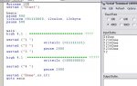
high 1 : high 4 ; ************************** ????
high 4 : high 1 ; ************************** ????
Interesting. Pin 1 is SDA, Pin 4 SCL so the first would just be a clocked data bit, the second though replicates an I2C Stop signal ( assuming both at zero then SCL high then SDA high ), second time round the loop the first would just keep 1 and 4 high as already set. Maybe try with the first removed ?
I can sort of imagine how it might be kicking the I2C bus and devices back into shape but cannot imagine exactly how that's working or why it would be necessary. If the PCF is holding SCL low for ACK that could explain hanging ( then timeout and reset ) and this would fix it but would also create a short from Pin 1 high through the 'open collector transistor' in the PCF to 0V ( ditto possibly for Pin 4 ). Seems odd though that there'd be no hang after other WRITEI2C.
Using HIGH also disconnects the 18X I2C peripheral so it would possibly it sees the bus lines high - that the TRISB bits do change is what led me to the discovery of the $AE shadow register which allows the 18X 'output only' pins to be made input.
The 18X is a bit odd with respect to I/O; the datasheet clearly states that PORTB pins must be made inputs for UART TX and RX yet when I've used TX on the 18X ( for MIDI ) there's not a single POKE to TRISB or the shadow register yet it worked ! With the HIGH's having been executed and I2CSLAVE setting the hardware for I2C comms there should be no further I2C comms, the PCF should stay with LED's latched on.
The plot thickens.
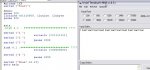
Last edited:
")