picaxe18x and pcf8574AP i2c problems

pippofjk

Member
Hi!,
I'm trying to connect my picaxe18x to the pcf8574AP i/o expander, via i2c.
In the pcf5874AP every I/O pin is connected to a led.

The picaxe cod is this:

begin:
pause 500
i2cslave %01111110, i2cslow, i2cbyte
pause 500

main:
writei2c (%10101010)
pause 2000
writei2c (%01010101)
pause 2000
goto main

If i'm not wrong:
%0111 for the AP version, 111 is the address (all connect to +V) and 0 is to set the chip into write mode.

The problem is that the i2c comunication dosen't work. The only thing that i see is all leds partially switched on, instead of flashing on and off, as like as write in the program...
i have configurated the i2c bus with 2 pull-up resistor (4k7) as wrote in the picaxe i2c tutorial

Can any one help me?

Thanks
 
Last edited:

hippy

Technical Support
Staff member
[ Merged the previous thread in the wrong forum with this ]
 
Last edited:

westaust55

Moderator
@pippofjk,

If the information in the post that eclectic has pointed you to does not resolve you problem you might wish to upload the schematic diagram for your circuit so that others can see exactly how your circuit is wired.

You make no mention of series resistors with your LED's but I presume that you have some (eg 470 Ohm) resistors - one per LED.
The PCF8564 can sink a total of 100mA for the entire chip.


An alternative to the PCF8574 is the MCP23017 which I have mainly been using of recent. This has ~20mA nominla (25mA absolute max) sink and source capability as well as a total of 16 input/output pins.
Keep in mind also the total current draw of 125mA in/out of the MCP23017.
 

hippy

Technical Support
Staff member
In your circuit you are requiring the PFC8574AP to source current when it can apparently only sink. Try connecting the LED+R between +V and the PFC8574AP pin.
 

hippy

Technical Support
Staff member
Ensure the anode of LED is towards +V and cathode is towards the PFC8574AP. Which code are you using, the same as in post #1 ?

I'm not familiar with the PFC8574AP, but it could be that using it with the LED's wired incorrectly has damaged it. Do you have another PFC8574AP you can try with ?
 

pippofjk

Member
If i try to connect the r+led for pcf pin to ground, the led is always on. If i try to connect the led, in your way, it's always off.

The code is quite differnet. for check up if the code is working, i have connected a led to an output pin of pic-axe, so:

begin:
pause 500
i2cSlave %01111110, i2cSlow, i2cByte
pause 500

main:
high 2
writei2c 0, (%11111111)
pause 2000
low 2
writei2c 0, (%00000000)
pause 2000
goto main


I have notice, that if i write the command "writei2c (%11111111)" the control led on picaxe stay always on (so the program is not running).
If i write "writei2c 0, (%11111111)" the control led, switch on and off (so the program is running), but on the pcf8574ap i have always the same situation as i write before.

p.s I'm italian, so sorry for my english that can non be correct at all.
 
Last edited:

westaust55

Moderator
Looking at the datasheet there are no register addresses for the PCF8574

a sample of my own code still regularly used which follows this concept is:
Code:
pattn2led: HI2CSETUP  i2cmaster, expand_0, i2cslow, i2cbyte
           HI2COUT (pattern)   ; [COLOR="Red"]<===== note no location given here[/COLOR]
           RETURN

This suggests that having the location the 0 immediately after the writei2c command is putting out zero to the PCF8574 as data then followed by the desired data. As the third byte you send is the data left in place for the duration the code should still work, but for now, with your your example program try:

Code:
begin:
pause 500
i2cSlave %01111110, i2cSlow, i2cByte 
pause 500

main:
high 2
writei2c (%11111111)
pause 2000
low 2
writei2c (%00000000)
pause 2000
goto main
If it is not working I think there is a chance you have a damaged/failed chip
 
Last edited:

pippofjk

Member
Without the location i notice that the program stay still in the first operation "writei2c".
I have already try i that way, but always the same result.

unfortunately i have only 1 picaxe18x and 1 expander i/o chip, so i cannot try with other chips.

I'm going to think that, one of the two chip, can be damaged...

Thanks for the help!
 

westaust55

Moderator
Something appears strange in that you report your program does not run when you omit the location from the writei2c command.

While your schematic seems okay, can you post a photo of your circuit so we can check the wiring as well.
 
Last edited:

hippy

Technical Support
Staff member
Something appears strange in that you report your program does not run when you omit the location from the writei2c command.
I missed the significance of that earlier ...

I have notice, that if i write the command "writei2c (%11111111)" the control led on picaxe stay always on (so the program is not running). If i write "writei2c 0, (%11111111)" the control led, switch on and off (so the program is running)
That suggests the I2C bus is hanging or a fault condition is causing a reset of the 18X. I cannot though see why the behaviour should differ in the two circumstances but that's possible if there is a fault.

I would recommend getting a new chip, with LED+R wired correctly and seeing how that behaves.
 

westaust55

Moderator
Problem maybe sorted. Did a test on my system . . .


It is the program

seems writei2c only allows a variable as a value inside the brackets. :eek:

try this:

Code:
;
      SYMBOL expand_0 = %01001110 ; %0100 = Chip ID, 111 = Addr - For LED's
      SYMBOL pattrn   = b5
	SYMBOL index = b6
; -----[ Program Code ]----------------------------------------------------
;
Init: i2cslave expand_0, i2cslow, i2cbyte ; for PCF8574 8-bit IO Expander

Main:
for index = 0 to 99
 pattrn = 0
 writei2c (pattrn)
 debug
 PAUSE 1000
 pattrn = 255
 writei2c (pattrn)
 debug
 PAUSE 1000
 next index
 
Last edited:

hippy

Technical Support
Staff member
writei2c only allows a variable as a value inside the brackets

We will look into that. There shouldn't AFAIK be any difference in using a variable or constant so this may be a particular issue with the 18X or the PCF8574. Thanks for your work in identifying the issue.
 

pippofjk

Member
don't work...
Always the same problem as shown before...

I think that probably there is something damaged in one of the two chip...

Thanks for the help!
 

westaust55

Moderator
Thanks hippy,

The PE does not flag an error if you have a value as decimal, hex or binary as the data in the witei2c command but only a variable within the brackets works.

for the writei2c command form manual 2 page 220:

Syntax
WRITEI2C location, (variable)
WRITEI2C (variable)

- Variable(s) contains the data bytes to be written.\


however using a constant value certainly works with the hi2cout command.


EDIT:

Have also tested with a 40X1 and same applies wrt the writei2c command.

I will test later this evening with an MCP23017 2 port (16 bit) IO expander and see if the same problem occurs. would not think it is the PCF8574 as in reality it is a binary value sent to the IO expander regardless of how it is presented within the PE code
 
Last edited:

pippofjk

Member
I've just try with another picaxe 18x version 8.6 (as the precedent).
Always the same problems...

Now i really think that the pcf8574AP could be damaged
 

westaust55

Moderator
I've just try with another picaxe 18x version 8.6 (as the precedent).
Always the same problems...

Now i really think that the pcf8574AP could be damaged
Do you try the new/second PICAXE with the code I posted for you?

If you add the HIGH2 and LOW 2 does the program keep running and the LED connected to PICAXE output 2 keep flashing?


I had a look at your photo but very hard to see the PICAXE board tracks, but as best as I can estimate where the tracks run, the circuit and wiring between the two boards seems to be correct.
 

westaust55

Moderator
@hippy

This code does work with a MCP23017 with a 40X1

Code:
SYMBOL expand_4 = %01001000  ;                , 100 = Addr 4 - For LED display as full circle
;

;
Init:   
        i2cslave expand_4, i2cslow, i2cbyte
        writei2c  0,  ($00,$00)    'IODIRA,IODIRB set port direction register to output
        ; hi2cout [expand_4], 8,  ($00,$00)  'INTCONA/B 
 Main:
        writei2c  $12,(%11111111,%11111111) 'turn off all the LEDs (output low)
        pause 1000
        writei2c  $12,(%01010101,%01010101) 'turn off all the LEDs (output low)  
        pause 1000 
        writei2c  $12,(%10101010,%10101010) 'turn off all the LEDs (output low)  
        pause 1000   
        goto Main
 
Last edited:

westaust55

Moderator
@hippy,

and this works with the PCF8574 both with and without the location part (ie the $0 ) with a 40X1

Code:
SYMBOL expand_4 = %01000000  ;                , 100 = Addr 4 - For LED display as full circle
;

;
Init:   
        i2cslave expand_4, i2cslow, i2cbyte

 Main:
        writei2c  $0,(%11111111) 'turn off all the LEDs (output low)
        pause 1000
        writei2c  $0,(%01010101) 'turn off all the LEDs (output low)  
        pause 1000 
        writei2c  $0,(%10101010) 'turn off all the LEDs (output low)  
        pause 1000   
        goto Main
 
Last edited:

westaust55

Moderator
think I must have had the PCF8574 address wrong when I did some first trials with the pcf8574 chip.


@pippofjk,

the code I posted for you to try was for "normal" PCF8574 not for the variant with alternate ID. Please try this

Code:
;
      SYMBOL expand_0 = %01[B][COLOR="Red"]11[/COLOR][/B]1110 ; %0111 = Chip ID, 111 = Addr - For LED's
      SYMBOL pattrn   = b5
	SYMBOL index = b6
; -----[ Program Code ]----------------------------------------------------
;
Init: i2cslave expand_0, i2cslow, i2cbyte ; for PCF8574 8-bit IO Expander

Main:
for index = 0 to 99
 pattrn = 0
 writei2c (pattrn)
 debug
 PAUSE 1000
 pattrn = 255
 writei2c (pattrn)
 debug
 PAUSE 1000
 next index
[code]
 
Last edited:

hippy

Technical Support
Staff member
@ westaust55

Thanks for the update. I'm afraid I don't have a PCF8574 ( of any kind ) to hand to do actual tests with but from post #24 it now seems that WRITEI2C, no address, using a constant, works with what you used - It would be fair to say that the WRITEI2C is fundamentally sound on the 18X, seems to behave as would be expected ( at least with respect to PCF8574, non-AP part ) ?

If so that would suggest an issue with the PCF8574AP chip or the specific case of the 18X interacting with an PCF8574AP.
 

pippofjk

Member
Yes, i try every possible combination.
the 2 different picaxe 18x version 8.6 has same behavour, same problems.
I also try your code, whit both addresses (the firsr times with %0100aaaX, the second with %0111aaaX), but nothing has changed.

I've read, in this forum, a thread of another user that as similar problems with picaxe 18x ver. 8.6 and the pcf8574AP
http://www.picaxeforum.co.uk/showthread.php?t=5252&highlight=pcf8574

So, or there is something wrong on my version of picaxe18x,
or my pcf8574AP don't work well..
 

westaust55

Moderator
@hippy,

I have two 18X chips bought at different times (and from different suppleirs) so I will check the firmware revision on both tonight and if different will run the same code for the PFC8574 (normal chip with %0100xxxx slave ID) and see that it works correctly.
 

westaust55

Moderator
18X i2c comms woes . . .

@ hippy,

okay more test tonight.

I must first explain that my tests at posts 23 and 24 were using a 40X1 not 18X as much to verify the writei2x was working into a PCF8574 - which it is with a 40X.


tonight I first checked my two 18X chips - both are firmware V8.8.

One of these is being used in a home brew datalogger and reading data from EEPROM, and barometric pressure sensor etc so i2c comms is working there with an 18X.

I then tried this code with a 40X1 and a small module with 2 PCF8574s that I built ages ago:
Code:
SYMBOL expand_4 = %01000100  ;                
Init:   
        i2cslave expand_4, i2cslow, i2cbyte

Main:

 	  b0 = $0
        writei2c  (b0) 'turn off all the LEDs (output low)
        pause 1000
        b0 = $55
        writei2c  (b0) 'turn off all the LEDs (output low) 
        pause 1000 
        b0 = $aa
        writei2c  (b0) 'turn off all the LEDs (output low)  
        pause 1000  
        goto Main
and it works so we have known working PFC8574s

I then tried the same code with an 18X and the PFC8574 module

- NO LED activity with either variables or constants as data and with and without a location value before the data.

- I noted in the terminal window (F8) that the PICAXE is outputting a xero (0) character via the SERTXD pin to the PC :eek:


Next I added an LED to output 2

Code:
SYMBOL expand_4 = %01000100 

Init:   
        i2cslave expand_4, i2cslow, i2cbyte

Main:

 	  b0 = $0
        writei2c  (b0) 'turn off all the LEDs (output low)
        high 2
        pause 1000
        b0 = $55
        writei2c  (b0) 'turn off all the LEDs (output low) 
        low 2 
        pause 1000 
        b0 = $aa
        writei2c  (b0) 'turn off all the LEDs (output low)  
        pause 1000  

        goto Main

No activity on either the direct driven of PCF drive LED's
but a lot of garbage arriving at the PC Serial terminal screen via AXE027 programming cable

I then disabled the writeic2 commands so code is:

Code:
SYMBOL expand_4 = %01000100 

Init:   
        i2cslave expand_4, i2cslow, i2cbyte

Main:

 	  b0 = $0
        ; writei2c  (b0) 'turn off all the LEDs (output low)
        high 2
        pause 1000
        b0 = $55
        ; writei2c  (b0) 'turn off all the LEDs (output low) 
        low 2 
        pause 1000 
        b0 = $aa
        ; writei2c  (b0) 'turn off all the LEDs (output low)  
        pause 1000  

        goto Main
result is:
- no characters see at the PC in the Terminal screen
- the direct connected LED (via resistor) on output 2 is flashing.


Next, complete disconnected the PFC8674 module and removed remark symbols (;) at front of the writei2c lines.

With no actual i2c devices connected, I get garbage to the PC terminal screen and no activity on the LED connected to output 2.

Now it is a while since I played with my data logger module - probably not since PE V5.2.7 installed, so I will try a test there with previously written program code and see what happens . . . . :confused:

Bit of a @@$%@? as I still had one of 3 PC';s here at home with V5.2.2 until last night and had just at end of night deleted that and put V5.2.7 on last home PC. So lost the change to test quickly with an old version of the PE tonight. :mad:


more later this evening . . . .
 

hippy

Technical Support
Staff member
With no actual i2c devices connected, I get garbage to the PC terminal screen and no activity on the LED connected to output 2.
I tried that ( on AXE090 development board also using 18X version 8.8 ) and it seems the 'garbage' is the PICAXE resetting when I2C pull-ups fitted but no I2C devices connected. A SERTXD at start of code should show that happening.

With the pull-ups not connected ( leg 7 and 10 N/C ) it doesn't reset and my LED on pin 2 is on for 1s, off for 2s which is as would be expected. With SDA and SCL pulled-down to 0V it's the same.

This seems to be behaviour of the on-chip I2C peripheral and I'd guess it's to do with sending a byte, waiting for an ACK which it doesn't get when pulled-high, times out, resets chip.
 

westaust55

Moderator
I have done a few more tests.

Fired up my 18X datalogger which would already have had a program in the PICAXE and got garbage on the PC terminal screen.

Downloaded a simple program to write the time/date to the RTC and read that back and it worked.


Back to the second 18X.

I have found that I get consistently different "garbage depending whether I use i2cwrite or write i2c

see attached pics.


writei2c always returns slowly one zero (0) per writei2c command

i2cwrite always returns many junk charcters per i2cwrite command


Inserted some debug commands but never got any variable data back to PC.

Out of curiosity I removed the pull up resistors and . .
- no garbage on screen an
- the debug side works so I see the variables that writei2c is given as data changing


=====
EDIT:
seems we are both finding the same thing wrt the pull up resistors
 

Attachments

Last edited:

westaust55

Moderator
Just tried with combinations of the pull up resistor. Seems to be related to having a pull up resistor on the i2c data line. If the clock line resistor is there DEBUG still works and no garbage on the PC terminal screen.


Could all this be to do more with the 18X part of the PE tokeniser?

Don't to think there is much more I can do here .. . will leave it to Rev Ed to investigate
 
Last edited:

hippy

Technical Support
Staff member
I have found that I get consistently different "garbage depending whether I use i2cwrite or writei2c
One shouldn't as they are simply two different keywords which generate the same code. The token code looks exactly the same no matter which I use. It's probably some anomaly with the serial side of things on the PC / AXE027 which is presenting things differently even though the same.
 

cylau

New Member
Do you remember I post the same problem in this forum a few years ago? I said this is a bug in 18X or the timing problem with the Philips PCF8574. Eventually, they don’t agree with me and close my thread. I shut up after this message.

It can be solved by 1) find a chip with hardware I2C module, 2) program the I2C with your own code, 3) Use another complier and programmer
 

westaust55

Moderator
Do you remember I post the same problem in this forum a few years ago? I said this is a bug in 18X or the timing problem with the Philips PCF8574. Eventually, they don’t agree with me and close my thread. I shut up after this message.

It can be solved by 1) find a chip with hardware I2C module, 2) program the I2C with your own code, 3) Use another complier and programmer
Your thread from Sept 2006 was raised back at post 27 in this thread.

The PIC16F88 as used for the 18X HAS hardware i2c and SPI fucntionality.
It is noted that the 16F88 implements SSP (Synchronous Serial Port), but not MSSP (Master Synchronous Serial Port). This means 16F88 can't be just configured to act as a i2c master, this must be done in software.


-see the datasheet:
http://ww1.microchip.com/downloads/en/devicedoc/30487c.pdf
Synchronous Serial Port (SSP) with SPI™
(Master/Slave) and I2C™ (Slave) [/quote

It is not a problem with the PCF8574 -the same problem occurs when the PCF8574 is disconnected but the pull-up resistors are still present and writei2c command is used.

Yet I can still write to and read from some i2c devices such as DS1307, 24LC256, and a barometric pressure sensor.
 
Last edited:

westaust55

Moderator
One shouldn't as they are simply two different keywords which generate the same code. The token code looks exactly the same no matter which I use. It's probably some anomaly with the serial side of things on the PC / AXE027 which is presenting things differently even though the same.
I fully concur that writei2c and i2cwrite are supposed to be just different keywords for the same function and should both give exactly the same token in the code downloaded to the PICAXE - which is what you indicate you can see in the code generated for download.

But with the pull-up resistors in place the "garbage" data to the Serial Out pin (going to the PC terminal screen) is consistently different for me last night with the same 18X chip as per the screen shots I posted.

= = = = = =

One test I did last night (but forgot to mention :eek: ) was to have my module with two PCF8574's connected, the clock pull-up resistor in place and removed the data line pull up resistor.

While the PCF8574's did not control the LED's, as expected due to the missing pull-up resistor, I did not get any garbage on the PC terminal screen and the DEBUG worked correctly allowing me to see the different values being loaded into the variables for the writei2c commands.

So the PICAXE program certainly does not reset when the i2c data line pull-up resistor is removed
Seems to me that the PCF86574's are not themselves the cause of the problems
but there is either resetting (as mentioned in the past) or other problems including activity on the Serial Output pin when the i2c data line pull-up resistor is installed.

For the record, I am also running my circuit using a 150mA 5V regulated supply.
 
Last edited:

westaust55

Moderator
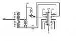
I tried a few more tests tonight with a 24LC16B EEPROM and two PFC8574 ICs:


Here is the basic code:

Code:
Symbol EEPROM_0 = %10100000    ; %1010 = EPROM, 000 = Addr/page 0, and 0 = control bit

SYMBOL expand_2 = %01000110


Main:                                             ; setup i2c comms to the EEPROM
i2cslave  EEPROM_0, i2cslow, i2cbyte  ; i2cbyte for 24LC16 and i2cword for 24LC256 EEPROM
writei2c 0, ($40, $41, $42, $43, $44, $45, $46, $47 )
Pause 20
debug
b0 = 1
b1 = 1
b2 = 1
b3 = 1
b4 = 1
b5 = 1
b6 = 1
b7 = 1
debug
pause 1000

i2cslave expand_2, i2cslow, i2cbyte

b0 = $0
debug

i2cwrite  (b0) 'turn off all the LEDs (output low)

b0 = $2
debug

i2cslave  EEPROM_0, i2cslow, i2cbyte 
 
 readi2c  0, (b0, b1, b2, b3, b4, b5, b6, b7 )
 
debug
Pause 1000

i2cslave expand_2, i2cslow, i2cbyte

b0 = $FF
i2cwrite  (b0) 'turn on all the LEDs (output low)

debug

Pause 10000
goto main

The results are:

1. with the EEPROM and PFC8574 all connected and NO writei2c statements rem&#8217;ed out, the program locks up at the line
i2cwrite (b0) 'turn off all the LEDs (output low)
I see b0 go to 1 and back to 0 but next changes to the value 2. Instead a complete reset of the program occurs.


2. with the EEPROM and PFC8574 all connected and the IO expander writei2c statements rem&#8217;ed out, the program runs and I can write and read from the EEPROM (changed data to EEPROM and always saw the latest data written into EEPROM)

This demonstrates that having the PCF8574&#8217;s connected to the i2c bus does not disrupt the i2c bus as I can still write and read to other i2c devices


3. with the EEPROM removed and PFC8574 connected and the IO expander writei2c statements rem&#8217;ed out, the program runs and as expected I read $FF from the EEPROM address

This demonstrates that writing and reading to/from an non existent device (ie the missing EEPROM) does not lock up/reset the PICAXE

4. with the EEPROM connected and the PFC8574&#8217;s disconnected and all writei2c command enabled the program locks up at the line
i2cwrite (b0) 'turn off all the LEDs (output low)
I see b0 go to 1 and back to 0 but next changes to the value 2. Instead a complete reset occurs.


5. I then added a supposedly unnecessary location byte to the writei2c commands for the PFC8574&#8217;s
That is: i2cwrite 0, (b0) 'turn off all the LEDs (output low)

And the program now cycles through without the PCF8574&#8217;s connected/

6. Reconnected the PCF8574&#8217;s and left the location bytes in the IO expander writei2c commands and . . .
The program continues to run


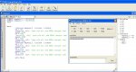
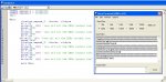
Still getting garbage at the SERIAL OUT pin of the 18X as seen on the PC&#8217;s terminal window and no LED activity on the PFC8574&#8217;s when the IO expander writei2c commands are not REM&#8217;ed out.


If I change the IO expander Slave addresses to %01111110 even though they are non existent at this address on my test rig,
(a) the program does continue to loop through with no writei2c commands REM'ed out
(b) I still see garbage via the SERIAL OUTPUT pin to the PC terminal window.


For some passes of the program tonight I added an extra 220uF cap to the power supply which provided no improvement.

Conclusions (maybe),

the 18X writei2c commands seemingly still need a minimum of 2 bytes whereas the 40X1 writei2c commands will work with a single bytes.

there is a problem with the 18X when a slave device for a connected PFC8574 (and seemingly PFC8574A) is used.

I have between last night and tonight confirmed no problems reading and writing to EEPROM and DS1307 RTC - even with PFC8574 connected

There is no problem addressing PFC8574's with the 40X1.


= = = = = = = = =

EDIT:

Found this thread where 18X with Firmware 8.4 worked with PCF8574, but firmware 8.5 did not work
http://www.picaxeforum.co.uk/showthread.php?t=3047

From the Firmware text file with the PE, supposedly, firmware V8.6 &#8220;ADDED SINGLE BYTE READI2C/WRITEI2C SUPPORT"
Some with Firmware 8.7 indicate problems akin to what I am finding with PCF8574 chips.
I have 18X with firmware revision 8.8 (According to PE V5.2.7). Both chips both a few months back about a month apart and from different Australia retailers.

But the Firmware.txt file with PE V5.2.7 does not list Firmware V8.8
 
Last edited:

hippy

Technical Support
Staff member
Some mechanism for indicating a reset of the PICAXE has occured has to be added to be able to distinguish when the program is properly looping or resetting. In none of my testing have I seen any 'garbage' other than when a reset has occured.

There does seem to be some issue with the 18X and a PCF8574 and more so with the PCF8574AP ( although they should behave identically AFAICT ).

It has been reported that the PCF8574 works with the 18X though that was using a zero location, not without a location. I don't know if anyone has had success when the location has not been specified. I am sure, but could be wrong, that the 18X had been used with other I2C devices which work the same way as the PCF8574; don't need a location, and haven't had a location specified.

One work round for the PCF8574 may be to use the data sent also as the location byte, for example, instead of "WRITEI2C (%01010101)" use "WRITEI2C %01010101, (%01010101)".

There seems to be some incorrect interaction between the 18X and PCF8574 which occurs only once the device address for the PCF8574 has been sent and presumably received but it is unclear what that may be. The best approach to determing what that may be is to look at what's happening on the I2C bus with a scope or logic analyser and compare what would be expected to what is happening. In the earlier thread it seemed that the I2C Bus was showing activity which was consistent with another compiler's version of its interacation on the I2C Bus for a PCF8574. We cannot see anything in the firmware which would cause a problem, nor any reason with and without location cases would differ.

It is indeed something of a mystery.
 

eclectic

Moderator
Only a little extra to add.

AXE091 board, with 20X2 / 18X / 28X1

New 8574P then a new 8574AP

Adr lines 0,1,2 to gnd.
P lines to Res> cathode LED > v+
i.e. sinking current.

Program(s)
Code:
;Forum 11 12 09
;http://www.picaxeforum.co.uk/showthread.php?t=14027


;#picaxe 18X
;#picaxe 20X2
#picaxe 28X1

begin:
pause 500
i2cslave %01110000, i2cslow, i2cbyte ;8574AP 28X1 / 20X2

;i2cslave %01000000, i2cslow, i2cbyte  ;8574P  28X1 / 20X2

; No response from 18X  (v. 8.6 or v 8.8)

pause 500

main:
sertxd ("1 ")
			writei2c (%11111111)
sertxd ("2 ")
			pause 2000
sertxd ("3 ")
			writei2c (%00000000)
sertxd ("4 ")
			pause 2000

sertxd ("Done",cr,lf)
goto main
Results:
20X2 and 28X1 work with both versions of 8754 (P and AP).
Flash LEDS and Sertxd “1 2 3 4 Done”.

18X (v.8.6 and 8.8)
No flashing. Sertxd “11111111111111” continuously.

e
 

eclectic

Moderator
I have no real idea WHY this works but,

18X (v.8.8) and NXP 8574AP are now
working together.
(Unless I'm hallucinating)

Code:
;Forum 11 12 09
;http://www.picaxeforum.co.uk/showthread.php?t=14027


#picaxe 18X

sertxd ("Start")

begin:
pause 500
i2cslave %01110000, i2cslow, i2cbyte ;8574AP 28X1 / 20X2

;i2cslave %01000000, i2cslow, i2cbyte  ;8574P  28X1 / 20X2

; No response from 18X  (v. 8.6 or v 8.8)

pause 500


main:
high 1 : high 4 ; ************************** ????

sertxd ("1 ")
			writei2c (%11111111)
sertxd ("2 ")
			pause 2000
sertxd ("3 ")

high 4 :high 1  ;***************************** ?????
			writei2c (%00000000)
			
sertxd ("4 ")
			pause 2000


sertxd ("Done",cr,lf)
goto main
e
 
Top