Newb Question...

laserhawk64

Senior Member
Hello all!

This is my second or third one of these. Hey, at least I don't post terribly often!

I came across an article about this on HackADay: http://www.hive76.org/the-no-video-game

Recently I thought... hey, I wonder if I could make one of these? ...and my spare Picaxe 08M starter kit came to mind (purchased from SparkFun back when they came with the cables...). I would definitely be replacing the chip in question with a 08M2.

Here's what I want to do:

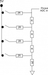
Input would be five buttons, run through a 74165 shift register (sorta like on the NES -- same idea, different chip).

There would be three outputs -- two LEDs (one red, one green) and a spare PC speaker (8ohm, 1/2w max, 2"dia, from the paleocomputing era of about the mid '90s). I know dang well enough to put a transistor (2N2222?) between the Picaxe and the speaker! I'll also put transistors on the two LEDs, just to be safe (they're 20ma exactly, and I don't want to push my luck).

So the pinout would be...

C.0 - "keypad" read enable
C.1 - green LED
C.2 - speaker
C.3 - "keypad" data
C.4 - red LED
C.5 - "keypad" sync (clkin from '165 and keypad clock source)

Gameplay would be fairly similar to the device in the link -- a series of beeps to simulate sonar; as the two submarines get closer, the beeps get more frequent (and less frequent if the player distances him/herself from the enemy sub). The player moves around via four directional buttons -- the traditional up/down/left/right directional pad sort of setup. The fifth button is a 'fire' button that sets off the depthcharge/bombthingy. When the 'fire' button is pressed, the LEDs both flicker (or blink, doesn't matter) and an explosion sound is played (sort of like the white-noise-inspired 8 bit 'explosions' you'd expect from an arcade game). This sound/flicker has a duration of about 2 seconds, and then the outcome is displayed -- green, enemy sub destroyed (game won); no LED, enemy sub intact. The enemy sub, if it gets close enough, will set off its own depthcharge/bombthingy, with similar effects but a slightly different possible readout -- red, player sub destroyed (game lost); no LED, player sub intact.

If either virtual sub is destroyed, the game is (obviously) over and nothing happens (except that the respective LED stays lit) until the player hits a reset button that cycles the power, or turns the game off completely.

I want to do the sounds as PWM or sound commands (probably will need to do straight PWM for the explosion effect). The SpeakJet is way overpriced for what I need at US$25 (SparkFun) and I can't easily locate another sound chip. I don't really need one anyways, as long as I can do this.

I have a couple of concerns, though, which is why I'm posting this...

(1) will a Picaxe 08M2 be able to do all that PWMing acceptably well for this game?
(2) to make the 74165 do its thing, I need to be able to output a 'clock' frequency that is at least compatible with that of the 08M2. Can I do this with the 08M2? It doesn't have to be 4MHz. It probably would be just fine at 40Hz. I just need to be able to output that.
(3) I'm sure there are other issues I'm not thinking of. If you folks could inform me of other problems I might have, that would be great.

Thanks, folks!

EDIT: made a goof already. Obviously I can't output anything on an input-only pin! So what I'm thinking is an external-to-the-chips 40Hz clockpulse generator, and outputting the signal to both chips to sync them together. This brings up a new question...
(2a) would the 08M2 be able to accept a square-wave (clock) input to sync with the '165?

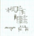
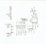
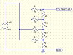
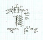
Also, drawing up a prototype schematic diagram right now. I'll upload it when I can; might be tonight, might be tomorrow.
 
Last edited:

PaulRB

Senior Member
Idea: instead of the shift register, attach the pushbuttons to a resistor ladder and then to an adc input on the 08m2. Figure out which buttons have been pressed with readadc.

Also, you won't need the transistors on those LEDs.
 
Last edited:

Buzby

Senior Member
Hi Laserhawk,

Looks a great idea, and I think you could do it with just one 08M2, by using some basic I/O saving tricks.

Drive two LEDs direct from one pin.
Modern LEDs are very efficient, they will be plenty bright enough at 10mA, so no need for transistors.
( However, why do you need LEDs at all ?. it's an audio based game ! )

Read a few pushbuttons using one analog input pin.
See http://www.picaxeforum.co.uk/showthread.php?7791-ADC-or-one-input-Keypad-Decoder&highlight=analog+keyboard for some ideas how.

Use a piezo instead of a loudspeaker then you won't need a drive transistor.

If you use one of those 'thumb joysticks' the final device could be as small as a matchbox.

Keep us informed, and we'll help you along.

Cheers,

Buzby
 

laserhawk64

Senior Member
Thanks for the suggestions! The resistor idea would never have occurred to me... so basically tie the pushbuttons to +V and then pipe them through five resistors (each of a different value), one resistor per switch? Or like an R-2R DAC ladder?

Primary reason for using the 2" speaker is that it's something I have that I don't need to take off a board. I guess I could use a peizo "speaker" tho...

The LEDs display win/lose condition at the end of the game, and flicker (or flash/blink/whatever) when a depthcharge/bombthingy goes off. I could probably get away with running them at 10mA tho...

I'd rather have the buttons than a joystick, because the two thumb joysticks at SparkFun (one is the regular type, and the other the slide type) are both resistive, and I'd rather have switches. Bottom line: it's just easier for me to get my head around. Also, a 4pk of pushbuttons is pretty cheap at Radio Shack, and I have one already -- just need another to match colors (4pk = 2 red, 2 black). No big.

I'll be putting this together on Radio Shack perfboard anyways, probably with point-to-point wiring.

Is there a way to ensure that the game gets "not more than" 5v from a 6v supply? Thinking of using a 4xAA battery holder, but I don't want to overvolt the Picaxe and smoke it. Most of the time the AAs will be 1.2v rechargeables, but there's always that one time when one thinks to stuff regular 1.5v disposables in there and then if there's no protection, it cooks. That would be bad!
 

Buzby

Senior Member
The resistors just need to be in a divider chain from +v to 0v, with the buttons connecting each tap point to ADC input, with a pulldown. 4 buttons, 4 different voltages.

The LEDs are wired to a single output, via a single resistor, so when the pin goes high one LED lights, when it goes low the other LED lights, and when the pin is set to be an input neither LED lights.

Try running your speaker through a 330ohm resistor, it may be loud enough.
 

laserhawk64

Senior Member
Didn't realize how cheap piezo speakers are... I think I can afford a us$0.74 part!

So for five switches... four resistors is what I'm thinking, each 51ohms. The buttons are connected in this order on the ladder...
FIRE
UP
DOWN
LEFT
RIGHT

...so FIRE is 5.3v, UP is 4.488v, DOWN is 3.366v, LEFT is 2.244v, and RIGHT is 1.122v. Obviously these values are a little... approximate... but they will work. Er... how "approximate" can I be with a Picaxe? I don't have a digital multimeter :eek:

Figured out the power supply as well -- talk about RTFM -- it suggests in the Picaxe Manual on the Picaxe website (hoowuddathunkit?) to stick a 1N4001 diode in between a 4*AA battery pack and the Picaxe circuit. Those diodes have a 0.7v drop to them, keeping the voltage at a safe level.

I'll have a schematic up sometime today. Warning: it will be hand-drawn!
 

laserhawk64

Senior Member
I have an analog multimeter. I think it's the 17-range one on that page (Cat#22-109). I really don't see the sensitivity going down to thousandths of a volt on that! (Oh, and its resistor readouts are all over the map, so I don't trust that one bit.)

EDIT: almost forgot. Here's the schematic.

Submarine Audio-Game Schematic.jpg
 

Attachments

MPep

Senior Member
You can also use READADC and then SERTXD the received values. This way you don't need to know the actual voltages, but what the PICAXE is 'reading'.
 

laserhawk64

Senior Member
Great! This is all wonderful... all I was really hoping to accomplish here was establish "is this possible" -- and everyone here is going well out of their way to say not only that it is possible, but how, and in ways that would have taken me quite some time to think of...

At this point, we should probably pause or stop the thread for a while -- I'm rather a bit poor, and it will probably be Christmas Day before I get the parts for this thing. I can program it once I've put it together.

...although, if you folks wanted to write the code for me, I wouldn't exactly object :D I've both the Picaxe and a Stellaris Launchpad, and I've yet to so much as touch either one, except for running the demo program on the Launchpad, purely to make sure I didn't receive a defective board... oh, and BTW, all my PC coding has been fairly limited and in QBASIC (remember that? it has line numbers! and it came with Windows 3.1!)...
 

Buzby

Senior Member
One of the best things about PICAXE is you can write and run the code without using a PICAXE !.

Just fire up the Programming Editor and you will be able to write and test 90% of your code in the simulator.

You can get all your Symbols defined, the overall structure of the program, the 'moving around' logic, the 'fire/hit/miss' logic, and loads more.
The only bit you can't really test is the sound generation, so just have a few Gosubs ready to fill in later.

I don't think anybody here is going to write the whole code for you, but we will help you write your own !.

You will get much further quicker with PICAXE than with that Linuxy TI thing, it's not even got real PWM !.

Cheers,

Buzby
 

Paix

Senior Member
For five switches, use five resistors. Make them approximately 2k each, so that you aren't unnecessarily dragging power from the supply line.

51 ohm is a little on the low side.
 

PaulRB

Senior Member
Will the player be allowed to press more than one button at once, eg up+left? If so, your R-2R maybe a better idea, otherwise you will get confusing readings if the player does press more than one together.
 

laserhawk64

Senior Member
Able to? Yes. Need to? Not really.

If someone could give me the right values for an R-2R ladder, I can do that. I just can't wrap my head around anything more than very simple arithmetic. TBH, I've a graphing calculator (I carry it in case of a division problem) so if I have the right formulas I may be able to do the math with that.
 

ZOR

Senior Member
Excuse my rudeness coming in on a thread, just to thank PaulRB for the idea of a resistor ladder into an ADC input. I was planning to put 5 switches into 5 inputs, now going to change, and now I will have spare inputs!!. Thanks, excellent, never thought of that.
 

Goeytex

Senior Member
Is there a way to ensure that the game gets "not more than" 5v from a 6v supply?

If using 4AA batteries then put two diodes in series from the battery pack to the Picaxe V+ Pin. This will drop the voltage to an acceptable level. 1N4001 Diodes will work fine.

You should also put a 100nf (.1uf) decoupling capacitor across the Picaxe +V and 0V pins.
 

premelec

Senior Member
Oh Schmitt!

@ZOR - note that you can switch the R-2R with a cmos Schmitt input gate IC if you keep the R >5K - You'll get debounce and if you use V+ same as PICAXE on Schmitt then ADC will give you accurate reading...
 
Last edited:

PaulRB

Senior Member
Excuse my rudeness coming in on a thread, just to thank PaulRB for the idea of a resistor ladder into an ADC input. I was planning to put 5 switches into 5 inputs, now going to change, and now I will have spare inputs!!. Thanks, excellent, never thought of that.
Ah, yes, one of my most brilliant ideas! Total lie. I was just the first in with the standard suggestion for this situation.
 

laserhawk64

Senior Member
I would love to implement an R-2R ladder... but I don't have the formulas to calculate it. My google-fu is weak (old man) so I'm at a loss to calculate this. Wiki has a formula that is almost helpful in that it calculates the voltage outputs, but I can't figure out how to get from there to the resistor ohmage values.
 

eclectic

Moderator
I would love to implement an R-2R ladder... but I don't have the formulas to calculate it. My google-fu is weak (old man) so I'm at a loss to calculate this. Wiki has a formula that is almost helpful in that it calculates the voltage outputs, but I can't figure out how to get from there to the resistor ohmage values.
1. See post #12

2. Read Manual 2 on
Readadc.
or readadc10

Then come back and ask. :)

e
 

PaulRB

Senior Member
But... most (inexpensive) pushbuttons are not spdt. Can an R-2R be made to work with simple push-to-make buttons? I'm not certain.

Would an alternative be a series of roughly doubling R values? Were not trying to make a perfect dac here, just make 32 distinguishable voltages for the adc to measure.

Eg. 1K, 2K2, 4K7, 10K, 22K on one side of a potential divider and 4K7 on the other. The 5 resistors on one side can each be shorted/bypassed by a pushbutton.
 
Last edited:

premelec

Senior Member
PaulRB - whatever suits you - in post 17 of this thread I mentioned the way I'd go - use a PB SPST into a CMOS Schmitt gate IC [outputs are effectively SPDT] and debounce as well as have a good low R switch... Just be sure you're not getting anything strange when n switches are pressed instead of only one at a time :)

PS usually I consider using all R and then paralleling or series connection of 2 to get the R & 2R values - then you can select with an ohmmeter out of a low accuracy lot of Rs if you need better accuracy - an octal Schmitt unit is 74HC7541 to drive the R2R network from PBs.
 
Last edited:

Paix

Senior Member
You merely need SPST momentary action push buttons for feeding an R2R ladder into the ADC input - as shown.

R2r.png
The above has been shown to be flawed and is no longer recommended.
B02.jpg
 
Last edited:

laserhawk64

Senior Member
Can't find a 74HC7541 @ Mouser, but I can get 74LS14s there. Trouble is, they're inverting. Nobody seems to stock a noninverting Schmitt trigger, so what I'm thinking is I could go one of two ways...

The switches that I'm getting from Radio Shark (teehee) come in two flavors -- NC and NO. I could get a pair of the NC 4pk's and be fine (although the switches would wind up costing twice as much) -- or I could simply stick a 74LS04 inverter in between the '14 and the R-2R ladder.

BTW, my multimeter is really acting up. Should I replace the batteries or ask for a new model for Christmas? Most recently it said that a perfectly fine 5v 2a wall wart was putting out about 4.25v...

Oh, right -- @eclectic: D'oh!! Forgot about that post, already... 2k + 4k for the ladder values, then.
 

PaulRB

Senior Member
You merely need SPST momentary action push buttons for feeding an R2R ladder into the ADC input - as shown.
Paix, have you tried this yourself and seen it work? Every schematic I have seen on the internet so far shows spdt switches, so that those points in the ladder are grounded rather than floating when buttons are not pressed. If so, great, it will help simplify laserhawk's design greatly, avoiding use of the Schmidt logic gates etc. and be useful for the rest of us in the future.

Paul
 

Paix

Senior Member
Paix, have you tried this yourself and seen it work? Every schematic I have seen on the internet so far shows spdt switches, so that those points in the ladder are grounded rather than floating when buttons are not pressed. If so, great, Paul
Short answer - NO.
Longer answer, I'm now running LTspice under Linux (WINE) and learning slowly, substituting links for the switches and running the simulation. it's CRAP - The simulation, not the program.
I too had come to the conclusion that everyone was using SPDT switches and felt that it had to be much easier, but I patently got it wrong.
I have, humour, information and a bit of honesty, so having been asked the question, I thought that it was incumbent upon me to have a look. What I found was not what I expected and frankly each key is unique, but borderline useless. In the longer term I will look at something else, but not today I'm afraid.
G362.pngG363.png
Taking the lower switch/connection in the chain as the least significant digit, the table shows the decimal representation of the binary sequence and the values at the output for a 5V source and 2k and 4k resistors. The last two columns are sorted by the output voltage - hardly intuitive. OK, it covers a worst case scenario, but it certainly isn't equally tempered. Ho hum!

Back to the drawing board.
 

laserhawk64

Senior Member
Actually, I have a source for cheap SPDT momentary switches.

Ever taken apart a computer mouse?

I live in a small town, and am friends with the owner of the local tech shop (OK, there are two tech shops; his is the better one). I can get a couple old mice no problem, and I've pulled them apart before, for other reasons.

The switches look like the one on the first page of this datasheet. The pins are even perfboard-able with 0.2" spacing...

I should have no trouble whatsoever getting two or three dead mice from that shop (free) and pulling the switches (which almost certainly still work) from them. Much cheaper than paying Mouser $0.50-0.75 each... I can make buttons for them out of wooden dowel, cardboard (or metal) washers, and a little paint. No problemo.
 

premelec

Senior Member
Great - use those with a capacitor [.01uF?] on the ADC input from the R-2R and that should give you pretty good debounce - BTW the octal Schmitt I mentioned is at jameco.com for about $1 I think... if you get dicey readings on the ADC it's likely the switches or local RF noise. You can set it up to look for two consecutive SAME readings to accept the value and such as well... and cats love playing with dead mouse balls!
 

laserhawk64

Senior Member
Pardon n00bish stupidity, but should the capacitor be between the switches and the ladder, or between the ladder and the Picaxe?
 

premelec

Senior Member
lh64 - capacitor simply from ADC pin in and V- to bypass some high speed crap that may be there - so from ladder output to V- and very close to the PICAXE pin with short leads- you're trying to suppress noise at the pin. And don't forget your .1uF chip bypass right at the PICAXE socket... V+ to V- :)
 

laserhawk64

Senior Member
OK, think I got it. Should be able to do up a revised schematic late tonight and post it sometime tomorrow morning or early afternoon...

EDIT: schematic drawn, just need a chance to scan & post. Tomorrow sometime will be good for that.
 
Last edited:

laserhawk64

Senior Member
Should have the schematic up in a little while... no promises, but I'm hoping...

EDIT: here it is!

Submarine Audio-Game Schematic, Rev.2.jpg
 
Last edited:

PaulRB

Senior Member
Are all your led symbols the wrong way around?

Not sure why you need 2 diodes to drop the battery voltage, one should be enough I think. 2 may unnecessarily stop the circuit working as soon as rechargeable cells start to get a bit low.

C.3 is unused. You could drop a stage off your ladder and connect an ordinary pushbutton to that as the "fire" button.

Other than that, looks great. Recommend prototyping on breadboard before plugging in that soldering iron.

Paul
 
Last edited:

MartinM57

Moderator
Yes, the LED symbols are the wrong way round - they forward conduct (fat end more positive than pointy end) and give off light in the process

Not really following the thread, but C.4 and the two LEDs is a bit odd? Whatever happens at C.4 (input or output - probably the latter?), when you turn the LED symbols around, you have two LEDs in series across 5v with no current limiting R. Bad News. What are you trying to achieve here?
 

laserhawk64

Senior Member
Good catches! I'll fix the LED symbols. One of many things I've never been able to keep straight... also, the two LEDs are connected the way they are to allow for tristate control -- one LED on when the pin is +, one on when the pin is -, and neither on when the pin is set to "input". (I forget now who made that suggestion.)

See 1st post for gameplay (you won't get the rest of this if you don't); as a note, the idea that both LEDs would blink/flicker/whathaveyou died when someone said, "oh hey you can have 'em both on one pin!" The idea with the LEDs is to have one LED flicker or blink to signify that a bombthingy is going off; which one blinks depends on who set off the bombthingy. The LED then either stays lit (end-of-game condition) or goes out (game continues) depending on whether the bombthingy killed a sub or not. (Sub-kill is end-of-game, one way or another).

So I want the green LED to flicker when the player sets off a bombthingy, and the red LED to flicker when the enemy sets off a bombthingy. If the player wins (enemy sub destroyed) the green LED goes on steady and stays it (if the LED goes out, player missed with the bombthingy). If the enemy wins (player sub destroyed) the red LED goes on steady and stays lit (if the LED goes out, enemy missed with the bombthingy). If the relevant LED does NOT stay lit, gameplay continues. I'll probably want to mention for clarity's sake that when an LED goes on steady, the game is over (win or lose) and so the whole thing enters a wait-state, LED lit, until a hard-reset occurs.

As an addendum to the gameplay listed in the first post... I would probably want to change one thing and add another. I'd want to shorten the explosion sound from 2sec to 1sec, almost certainly. The thing to add is demanded by how computers "think" -- the way I envision the enemy sub deciding to set off a bombthingy, is that it's in range. If it's in range, 100% of the time it will set off a bombthingy. This could cause a bit of a looping problem -- where it sets off one bombthingy after another until it blows the sea into orbit. Not good. So I'm thinking that, when a bombthingy goes off, the force is enough to blow both subs back a goodly bit, at least twice the range of the bombthingy.
 
Top