Newb Question...
- Thread starter laserhawk64
- Start date
inglewoodpete
Senior Member
Two more things to fix or simplify. The download circuit is drawn wrong. The tip is earthed (0v/common)
Unless you're trying to produce 32 different key values from the keypad, the circuit is way, way too complicated. Use 5 simple push-to-make twitches (tactile ones are ideal) and 5 or 6 resistors in a chain. Keep it simple and breadboard each concept first!
Unless you're trying to produce 32 different key values from the keypad, the circuit is way, way too complicated. Use 5 simple push-to-make twitches (tactile ones are ideal) and 5 or 6 resistors in a chain. Keep it simple and breadboard each concept first!
laserhawk64
Senior Member
inglewoodpete, the idea with the R-2R ladder is to make it so that when someone hits two buttons at once, it doesn't freak ")
Thanks for the tip on the, er, tip. I'll fix that.
Thanks for the tip on the, er, tip. I'll fix that.
inglewoodpete
Senior Member
Why? I doubt that other manufacturers would go to that expense. What would happen if two or buttons were pressed at once? You'd still get an output, still not a valid one. Unless you want to specifically take no action when those mis-keys occur. It must be a real problem but then I'm not a gamer.inglewoodpete, the idea with the R-2R ladder is to make it so that when someone hits two buttons at once, it doesn't freak
laserhawk64
Senior Member
OK, so how would YOU do that part of the circuit, such that two buttons could be pressed without giving an invalid input?
Hi,
What is required to happen if two (or more) buttons are pressed concurrently? i.e. Act as if only one was pressed (does it matter which?), Act on both, or as if none was pressed? Can any combination be pressed (some can be avoided by using "rocker" switches in pairs for example)?
Personally I'd try a sequence of resistors of say 1k, 2k0, 3k9, 8k2, 16k and 33k through each switch to ground and perhaps 100k pullup. Some of those values might be made with pairs of resistors but you'll probably use less than in a ladder. With care the A/D converter should be able to individually detect any combination of buttons pressed (4 buttons should be fairly easy, a 5th is getting tight with normal resistor tolerances).
Or if you just want to reject two buttons being pressed, use say 1k0, 1k2, 1k4,1k6 and 1k8, then any value detected as less than 1k0 indicates multiple buttons are pressed.
Cheers, Alan.
laserhawk64
Senior Member
I want it to act on both.
inglewoodpete
Senior Member
In the past, I have been caught up in the dilemma you appear to be in now. Pressing 2 keys at once is not valid Ie an error. To the user, pressing the wrong button is an error. Also, accidentally pressing any button when you did not mean to is an error. In reality, it probably does not matter which error occurs. An error, or invalid input, is just that. Your code will behave predictably for any keypress, whether the keypress was valid (intended) or not.OK, so how would YOU do that part of the circuit, such that two buttons could be pressed without giving an invalid input?
Alan has described a couple of ways to detect some input errors. A third option would be to connect a high value resistor (Eg 100k) between the ADC input and +5v rail. Then use a chain of 6 resistors of lower resistance (Eg total resistance of the chain of 10k) between the +5v and 0v rails. Some design work would be required to select suitable values. 5 x PTM switches would then connect between the 5 junctions of this resistor chain and the ADC input. Any single key pressed would result in one of 5 different ADC readings, each within a narrow band. If your design is right, when more than one key is pressed, the resultant ADC value will fall outside the 5 expected values.
Hi,I want it to act on both.
I haven't followed all of this thread so went back to #1:
Is this still the aim? Is it really necessary to detect, for example, if both up and down buttons are pressed at the same time (if so, what is meant to happen)?The player moves around via four directional buttons -- the traditional up/down/left/right directional pad sort of setup. The fifth button is a 'fire' button that sets off the depthcharge/bombthingy.
If you can decide which combinations are actually "valid" then you may be able to simplify the design. Perhaps use a second input for the fire button (it's often hard to find a use for that single "input only" pin), or rockers for U/D and L/R, so that you only need to resolve up to perhaps 16 possible analogue levels on an A/D pin (much easier than 32).
Cheers, Alan.
I fully agree with IWP's method, its what i had thought from the start, but then got lost in the thread with various resistor ladder methods.
Keep it simple and functional.
Do which switch pressed in software like IWP suggests, and not rely on hardware, that is what micros are good for, lack of hardware.
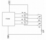
I simply would do it like this.
Keep it simple and functional.
Do which switch pressed in software like IWP suggests, and not rely on hardware, that is what micros are good for, lack of hardware.
I simply would do it like this.
Hi,
IMHO that seems to be the worst of all worlds. It appears to use four PICaxe pins and five different resistor values to give one less than the requested number of "buttons".
If the pins are available, then you can use the PIC's internal pullup resistors and no external resistors are required (you might want to include one in a common "earth line" to the switches as protection in case a pin gets accidentally set as a high output).
Alternatively, five resistors of different values can easily be arranged to give one of 16 levels on a single PICaxe analogue input pin, followed by simple software decoding. The analogue tolerances really only become more tricky with greater than 16 potential analogue levels (i.e. 5+ switches).
Cheers, Alan.
Last edited:
laserhawk64
Senior Member
I'm not averse to using a larger Picaxe if needed -- I can afford to pay a dollar extra for a 14M2 if that would help...