mosfet drivers high vs low side

vk6bgn

New Member
pbateman,

Search the forum with the words "POKE T2CON". This should give you about 5 or 6 hits on the subject for slowing down the PWM output from 4Khz. to 1000Hz. or 250 Hz. It's as simple as POKEing the T2CON register with the right value. I think this possibly POKEs some sort of Prescaler for a 4:1 or a 16:1 reduction for the PWM output.

Have a search of the forum mate, you should find what you're looking for.

"The Addict"
 

Dippy

Moderator
Yes, I'm afraid I couldn't udnerstand the use of an N channel for exactly those reasons.
There are some N-channel based MOSFET high-side switches but, as you say, they have level-switching charge-dumping doo-dah-womping built-in.
And of these varieties there are several s/mount 1A rated devices for under 70p.

But for butchness/price you can't beat a good P.
 

vk6bgn

New Member
Oh,

I think I have read most all of the 5 pages of this thread and I did not read anything about installing a "Kickback" or "Flyback" rectifier in parallel with the motor. This rectifier configuration is know by other names of which I can’t remember. Possibly there was something written in the thread but I missed it. So I will continue to babble on.....

In regards to the MOSFET getting hot when driving the 10 Amp DC Motor.... I found that installing a "Kickback" or "Flyback" rectifier in parallel with the motor, but in the opposite direction of current flow works to alleviate a lot of the heating in my motor project. This rectifier must be in the right configuration or it is a short circuit around the motor!!! This clamps the spike produced every time the PWM pulse shuts off and the motor magnetic field collapses onto itself. In my project, I used a 35 Amp bridge as my 10 amp motor project only switching at 250 Hz. But I know they make high speed rectifiers for applications pulsing in the KHz. region. And even ultra high speed rectifiers too.

Plus, I think this pulse generated by the collapsing motor field is in the opposite polarity to the supply that produced it. So if you install the Kickback rectifier in parallel with the motor, (polarity sensitive!) this will divert the spike produced by the motor and redirect it back through the motor when the PWM is off. Thus harnessing a small bit of extra power that would have normally been lost.

My 2 cents worth.

"The Addict"
 

Dippy

Moderator
I did something along those lines of that for an H-Bridge.
It does work and provided a little extra oomph for no extra supply current.
The effect was more noticeable at higher F PWMs but at those higher Fs the power reduced anyway so I gave it up. But it's certainly worth consideration.
 

Michael V

Senior Member
P Channel

Hi Guys,
Just to close this off, i thought i'd let you know I progressed.

The attraction of the 2N7000 was that it was a mosfet the size of a transistor, and i needed a switch but not a big one. I didn't know about p Channels then, but i do now.

Also, when switching from 5V, there was no way i could get more than about 3.6 V, which was too low for my logomatic data logger. Very frustrating, i'm sure there is an explanation.

Following all the discussions about PNPs and NPNS and "why would you NOT use a P channel" plus Dippy's neat sketch, I had a closer look at the PNP . I only wanted to switch on device that would not consume more than 100mA, all up. Jaycar doesn't have p channel mosfets that small. The larger size of the TO 220 was going to be a problem.

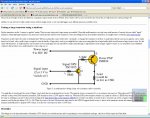
Well, i already had ( just in case ) a PN200 PNP Transistor ( $0.25) to-92 that would carry 500mA continuously. I figured that would work. With fairly minimal adjustment to the circuit board i fit in the PNP, approximately as per Dippy's circuit for the Mosfet, but minus the 100K resistor. I did this because i found the attached almost identical circuit on the Net from University of Western Australia, with good explanations for a beginner like me.

Well it works just fine, and gives higher voltage than the inverting NPN N Channel combo. Just goes to show - the right tool is half the job.

so, why is the 100K necessary for a Mosfet and not for a transistor combo? Is it something to do with the mosfet capacitance i have been reading about?

Michael
 

Attachments

Last edited:

moxhamj

New Member
The 100k is there on the mosfet to keep the gate at a definite voltage when the transistor is off.

That link you gave is a great explanation of how to use a small transistor to drive a big one. The mosfet equivalent is Dippy's circuit and it is the same but with that extra "pullup" 100k resistor. The detailed explanations are more complex - maybe just follow the 'recipe' on this one.
 
Last edited:

Dippy

Moderator
DrAc: go back and edit quick before the pedants get you :)

Yes, for many simple switching apps N-Chan/NPN and P-Chan/PNP are interchangeable. You've just got to be aware of a few things:
1. How the Gates vs Bases behave.
2. Transistors (BJT/MOSFET) are not quite the same as relays.
3. High speed (<uS) switching of FETs is a different matter.
4. MOSFETs have capacitance all over the place so if scoping the 'output' without a load then it may look funny. Remember this especially if testing a PWM drive.

If you experiment and take notes it is a very useful education.
As you have found out they are an excellent method for simple power switching and very useful in all sorts of circuit. In fact right now I'm using MOSFETs for PWMing and switching sub-circuits within a big circuit - ideal.
I've even got a resistor in series with me LED ;)
 

moxhamj

New Member
You are quite right Dippy. I have edited it now as it wasn't the correct explanation. I wrote that walking out the door and it was a bit rushed!
 
Last edited:

Dippy

Moderator
"I wrote that walking out the door and it was a bit rushed!"
- you got some darned flash light-weight blue-tooth /WiFi pocket PC then? :)
 

moxhamj

New Member
No, just a sad tragic forum addict (with long arms) :)

Re "I only wanted to switch on device that would not consume more than 100mA, all up." - this still could be done with really cheap BC547s and 557s. If you have it all working, then that is all fine, but cheap and cheerful transistors are very useful in this sort of application.
 
Last edited:

Michael V

Senior Member
Thanks

Thanks guys,
The cheap transistors will do the job, it seems, for a low power device of 100mA.

For switching a 1 amp or bigger Solenoid valve on & off with the Valve connected to ground, then Dippy's npn transistor - P channel mosfet circuit would be the best choice.

But for PWM on a proportional solenoid (linear actuator) or motor control it seems the high side driver chips and n channels are the go (other thread). This is because in the transistor - P channel mosfet combo the capacitance of the mosfet must escape, and and the stored energy can''t get away quick enough through the resistors, meaning the mosfet will have significant resistance between rapid switching end up cooking. (did i get that right?)

Thanks once again.
 

Dippy

Moderator
Nearly, but not quite.
ALL MOSFETs (P and N) have a significant capacitance. Check out the Data Sheet figures usually under the heading "Dynamic Characteristics". You will see a bunch of pFs.

For fast stuff you need a driver to suck that charge out and shove some omph back into the gate regardless of N or P channel.
You highlighted a N channel driver for High/Low. Well, it's doing the sucking and shoving but at the voltages necessary to make an N channel work as a high-side driver - it relates to gate/source voltage.
A P channel driver does a similar thing but it will take the gate down to nearly Gnd/0V and shove it back up to Vss with great gusto. Remember, you need to get a pile of coulombs out and back in at f.High speed - ideally < 250nS. Do the maths for instantaneous current.

Obviously the greater the R/Z component in your driving the slower that Gate charge is sucked/shoved, as you'll know from any R/C circuit with your exponential curves.

For an easy life switching a 'Logic' level N channel as a low sided switch is a piece of cake, but do rmember, you STILL have capacitance. A PIC o/p is incapable of doing a fast job. It can do it , of course, but not at a 'speed' good enough for fast high-power PWM.

That little NPN/P-Chan combo: the NPN will suck the charge out of the gate reasonably well, but it relies on the resistor to shove it back when the NPN switches OFF. So, if you looked at the MOSFET output you would see a sharpish leading edge of a square wave and a soft trailing edge. You could improve the performance by replacing the Gate-NPN res with a low one say 47R and replace the Gate/Vss res with say 470R, but this increases the current just to make it work.
For the lower-end Power MOSFETs and light load this is OK. But those non-sharp waves mean that the MOSFET is spending a significant amount of time as a resistor. For PWM and a heavy load this is NOT good.
And as you turn up the frequency or shorten the duty-cycle those soft edges become even more significant as a percentage compared with full on/full off. In fact it could end up looking like sawtooth wave - bad!
When the MOSFET acts as a resistor, there is a painful consequence. Good old IsquaredR.

A proper driver essentially replaces the piddly signal-level NPN with something more manly and replaces the Gate/Vss resistor with something that is a low resistance/impedance path to Vss - but operates exactly out of phase with the NPN side, ideally to get a strong, sharp IN/OUT/IN/OUT to the Gate with no overlap.
If you look at some of the drivers linked earlier using discretes you should get the picture as to the principle of operation. Drivers are basically a well designed, complimentary pair which are well matched and can handle a high current from a logic input.

Many driving circuits can also suffer from 'shoot through'. No I didn't make that up. It means where both of the arms of the complimentary pair are on and the current shoots through wastefully. An ideal driver has none.

There are many poblems getting a home-brewec driver circuit to work well, and unless you want something special and you have the experience/equipment to do it, just go and buy a driver chip. For fast/efficient/cool PWM you will need it, for N or P channel.

However, if it a learning thing then DO experiment with discretes, it will be very useful experience.. if you have the time you will gain a lot of knowledge. Mind you, if you don't learn then you'll be back here wondering why it doesn't work :)

If you truly want to get to grips with all this then go to some Manufacturers's sites and get their Application Notes on driving FETs. They can explain it far better than my efforts. And once you have absorbed, learned and tried then you can tell others. Just remember: components aren't 'perfect'.
 
Last edited:

Michael V

Senior Member
Thanks

Hi Dippy,
your explanation is excellent, i think i even understand it.

It is not that long ago that my most significant achievement was getting the 08M to switch a relay on and off to make my Christmas lights flash. And now i'm switching on transducers, reading in PWM from accelerometer modules, testing for repeatability and speed , writing via I2C to LCD displays, to SD cards and computers. And i'm taking measurements on million dollar machinery that no one else has done before. Thanks to the advice on this forum. (Eventually i want to retrieve the Data wirelessly, and I already have the Xbee modules).

So as far as learning goes, i have a head full of it! Learning about high side vs low side and p and n channels was enough of a challenge. When i get around to PWMing proportional solenoid valves i will stand on the shoulders if giants and use the driver chips!

Thanks again!
 
Top