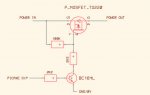
High Side, Low Side - What Rick said -
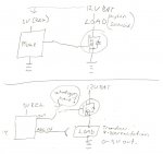
High side low side refers to where the FET is - If it is on the ground side of the load - i.e. between the load and 0 volts it is low side.
If it is between the load and the positive voltage it is high side
(assumes an N channel FET)
You can have the load on either side, but if you use
an N-ch MOSFET Low Side, e.g. load between the MOSFET
and the NEG/0V it messes with the VGS voltage/resistances
and can be less efficient.
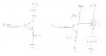
MOSFETs can be tricky beasts in some circumstances but
they are "usually" easier to use than BJT transistors.
5V-10V on the gate and they turn ON, doesn't get much simpler.
( with virtually no current (minimal) draw from the supply to GATE )
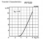
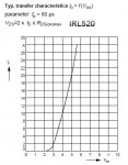
When a MOSFET starts to turn ON it acts like a variable
resistor until the full Gate (saturation) voltage is applied, e.g. 10V Vg.
This is assuming you want to use the full current capability
of the device, e.g. 22A, and the RSD-on stated, e.g 0.014 Ohms.
However this can change if you only require 1A.
The MOSFET may start to switch ON at 3.2V and you will
get near the RSD on with only 4.7V Gate voltage applied.
If you then try to draw more than the 1A the resistance
RSD on will shoot up and the mosfet will quickly get hot.
In many cases excessive heating points to the MOSFET
not being turned ON hard enough, too little Gate VOLTAGE.
(never mind the current MOSFET Gates don't use any, just the voltage)
Another thing that bugs me is the insistance of the "know it nothings"
when they refuse to use a Gate resistor,
ALWAYS USE A GATE RESISTOR,
the resistance is not needed but they are used as a
FAILSAFE device
in the case of a complete MOSFET failure where the full supply voltage could
backfire up the gate input line to the rest of your circuit.
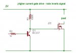
Gate discharge resistor-
In some cases a Gate can be held ON with no input present. This is due to
internal capacitance. As good practice a resistor is placed from the Gate
to the Source (Neg/0V, N-ch). This resistance can be very high, from 47K
Ohms to 1 Meg, it will ensure that MOSFET always turns OFF when the
input is Low. (or removed )
Another thing that can catch you out, is when using a Gate resistor in
conjunction with a Gate pulldown (as above) it does form a Voltage Divider.
Using a 5V Gate input supply via a 4K7 Ohm resistor and a 47K Gate
pulldown, you will now only get 4.55V into the Gate. Be aware of this.
PWM Speed and Motors-
If you read the MOSFET Application Notes from various sites, they
usually recommend PWM of 4KHz to 20Khz for use with Motors.
I tend to use 4KHz as it seems to work well and the motor noise
isn't that bad (it will depend on your particular motor type).
Another reason you may not immediately realize is that @ 4KHz
PWM 50% ON and 50% OFF is fine. But what happens at 1% - 2%
Duty and 98% - 99% Duty the ON/OFF pulse width is VF-FAST !
You can divide /5 that if you use 20KHZ PWM.
Which brings us to BACK EMF protection.
Never rely on the MOSFET internal Doide for full BACK EMF
protection when using Inductive loads or Motors.
If you use very high PWM frequencies you will need High
Speed diodes for protection as standard ones are too slow.
There are a lot of very good data sheets and application notes
on MOSFETs and how to use them, at sites like IRF and ST, etc.
Go get some, even if they are only for future use.
")