Could you post your circuit? What I'm working on is part of my first solar project. By the way (I could google but), what are IMP and ISC?
Its solar panel terminology.
IMP =
Current Maximum Power
ISC =
Current Short Circuit (which is generally an Amps or so higher than IMP)
I never drew a circuit as such. It was just drawn on a piece of paper at the time.
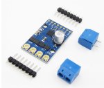
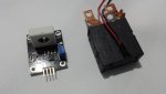
But I can give a run down of its operation. Plus here is a picture of the current sensor and the motorized 80amp switch used.
The current sensor has an ADC output and an Op-amp onboard. So the current limit can be tune via a digital output(pot) or hard coded ADC.
One of the main solar array feed cables would go through the current ring. And the Panel voltage was also monitored, to differentiate between voltage drop via load and just by cloud cover or at night. And also to determin when the motorized switch went open circuit.
Due to the fact the whole circuit is powered by solar. Meant that it would terminate its own supply when the switch goes open circuit under a short condition. This was overcome by driving the Picaxe and motorized switch by a super capacitor.
If a short did occur, the motorized switch could be reset after the fault was fixed via a momentary switch that closed the motorized switch contacts again. The Picaxe also uses the panel voltage(or lack of) to determine if the short is still present, so it couldn't be reset if that was the case.
If I remember correctly.. the most fiddly part was isolating the ADC voltage read of the panels, from the rest of the circuit..
Plus it has a warning buzzer and LEDs to show state conditions.