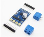
Measure current on 12V line

lbenson

Senior Member
I have ordered a 12V (non-solar) motion sensor light. I assume it will draw a nominal current when not sensing motion, and a much greater current when the light goes on. How best do I detect the increase in current with a PICAXE so that I can tell when the light has switched on?
 

lbenson

Senior Member
Ah, thanks. I have some of those Hall effect current sensors, but my mind had gone blank.
 

matchbox

Senior Member
I often use either Hall or Shunt current sensing on my picaxe projects. Its helpful for motor load sensing.
Or as you're using it for.. A secondary means of detecting if the device is operating, and not just a high output state from the mC.

Depending on the voltage scaling from the current devices output. You many have to use FVR 2048 or 1024, to get good resolution.
 

Rampz

Well-known member
Its helpful for motor load sensing.
I'm interested in motor load sensing, i thought about measing voltage drop across a shunt, but with a few amps will need to be a good sized shunt i thought, so really stayed away from the subject, but would be good to see people ways of doing this. Had to edit post was obvious how they are used from the product link, never seen them before
 
Last edited:

matchbox

Senior Member
I'm interested in motor load sensing, i thought about measing voltage drop across a shunt, but with a few amps will need to be a good sized shunt i thought, so really stayed away from the subject, but would be good to see people ways of doing this.
Now days there are many breakout boards with either a hall or shunt, that have a current sensor chip on board. This makes using them reasonable easy.

I also have used many of these H bridge driver. Which have their own inbuilt shunt for load sensing.

I would say my most over complicated picaxe project was with a Hall sensor ring and a low resistance motorized switch. Used as an electronic circuit breaker for a solar array.. Its advantage was that it could be tuned to go open circuit just over IMP and just under ISC.. Rather than the way most installers stick a huge fuse in circuit that the panels wouldn't stand a chance of blowing out. Well at least not before it melted the insulation off the wires, between them and the short.
 

Attachments

lbenson

Senior Member
Depending on the voltage scaling from the current devices output. You many have to use FVR 2048 or 1024, to get good resolution.
I won't need much resolution--all I'll need to sense is the difference between the minimal amount that the motion sensor circuitry needs to do its work, and the much greater current when the 30W LED is turned on.

my most over complicated picaxe project was with a Hall sensor ring and a low resistance motorized switch. Used as an electronic circuit breaker for a solar array. Its advantage was that it could be tuned to go open circuit just over IMP and just under ISC
Could you post your circuit? What I'm working on is part of my first solar project. By the way (I could google but), what are IMP and ISC?
 

hippy

Technical Support
Staff member
I won't need much resolution--all I'll need to sense is the difference between the minimal amount that the motion sensor circuitry needs to do its work, and the much greater current when the 30W LED is turned on.
It might be worth looking at how much the 12V power supply sags when the LED comes on. If there is enough of a sag a resistor divider and ADC may be good enough.
 

matchbox

Senior Member
Could you post your circuit? What I'm working on is part of my first solar project. By the way (I could google but), what are IMP and ISC?
Its solar panel terminology.
IMP = Current Maximum Power
ISC = Current Short Circuit (which is generally an Amps or so higher than IMP)

I never drew a circuit as such. It was just drawn on a piece of paper at the time.
But I can give a run down of its operation. Plus here is a picture of the current sensor and the motorized 80amp switch used.

The current sensor has an ADC output and an Op-amp onboard. So the current limit can be tune via a digital output(pot) or hard coded ADC.
One of the main solar array feed cables would go through the current ring. And the Panel voltage was also monitored, to differentiate between voltage drop via load and just by cloud cover or at night. And also to determin when the motorized switch went open circuit.

Due to the fact the whole circuit is powered by solar. Meant that it would terminate its own supply when the switch goes open circuit under a short condition. This was overcome by driving the Picaxe and motorized switch by a super capacitor.
If a short did occur, the motorized switch could be reset after the fault was fixed via a momentary switch that closed the motorized switch contacts again. The Picaxe also uses the panel voltage(or lack of) to determine if the short is still present, so it couldn't be reset if that was the case.
If I remember correctly.. the most fiddly part was isolating the ADC voltage read of the panels, from the rest of the circuit..
Plus it has a warning buzzer and LEDs to show state conditions.
 

Attachments

Last edited:

lbenson

Senior Member
IMP = Current Maximum Power
ISC = Current Short Circuit (which is generally an Amps or so higher than IMP)
Right, thanks--label for my panels has ISC and IPMax. I had blanked out "I"=Current.

I've bought a PV Combiner Box (to parallel my panels, with input and output circuit breakers), which may do what your circuit does. Is your shutoff on the panel-to-solar charge controller side, or battery-to-load side? (I'm still working out these issues.)
 

matchbox

Senior Member
Is your shutoff on the panel-to-solar charge controller side, or battery-to-load side? (I'm still working out these issues.)
Its on the panels to the charger side. Near the panels. Which is why I made the electronic fuse. Because solar panels don't produce a high impulse current when shorted, like a battery does. Which makes it impossible for a solar panel to blow a fuse or trip a circuit breaker in any short amount of time.
But something like this may exist now days.. This was back in 2012.

What lead me to do this, was frost build up on the solar trackers actuator, stalled it. This caused every component on the switch mode regulator to get desoldered and fall off the board. Which woke me up to the fact there is a lot of power here, but it can't blow a fuse.
Plus I also redesigned the tracker driver.. It also checks the load current when driving.

The battery to the inverter and DC load side, have conventional fuses.
 

matchbox

Senior Member
When it comes to sensing load current for a motor drive or actuator. There are some things to take into account. Which your code needs to handle.

* The drive current
* The overload current
* The impulse startup current of the motor and gearbox assembly (which can be up to 4x greater than in operation)
* The ambient temperature of the motor/gearbox and all its attachment (they will be tighter when cold and pull more current)
* When a motor is stalled, it pulls a little less current than under a heavy load.

All my programs take these factors in to account to some degree, by using a multi-stage load checks based on, Drive time and Positioning of the driven device.
It also gives the motors overload detection two attempts, with a slight increase in the load detection setting.... Before it will shut off and send an error message.

This maybe more effort than most people would go to the trouble of.. But I find the effort in the beginning save repair time later.
 
Last edited:

lbenson

Senior Member
Thanks very much. So I think the design you use is supposed to be covered by the paralleling PV Combiner Box which has separate 15A breakers for each panel, and a 63A breaker for the combined current of the panels (which theoretically my 3 8A ISC panels could never overload).

Yes, a lot has changed in 10 years. My planned design is already "old school" when compared to the present range of server rack mounted battery + inverter + solar charger devices, with a lot of features in a handy package.
 
Last edited:
Top