Hi,
Very interesting little setup! looks great. ..... But using the pins of the 08M2 directly doesn´t give much current to work with. ....
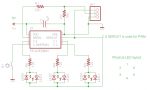
Presumably you're referring specifically to Rick100's design in post #3? Those POKESFR's are quite "advanced" programming and might not be trivial to convert to even another PICaxe*. That also makes it quite difficult to predict how the design might best be adapted for a brighter output, so I'd start with KISS (Keep It SimpleS). The 120 ohm resistors can probably be (safely) reduced, because the LEDs are bridged between a HIGH and a LOW PIC(axe) output pin, the current will be limited by the Pull-Up FET (which is always "weaker" than the Pull-Down). With a supply rail of 4.5 volts or less the resistor can probably be removed entirely (short-circuited), but for a higher voltage it might be wise to try a few resistor values to achieve the maximum 25 mA rated output pin current. If that's still not bright enough then maybe look for some more efficient white LEDs.
")
Indeed, it's not easy to add external FETs to emulate a Tri-state output, but it might be possible if suitable (complementary) FETs can be found (or selected) with an
actual gate-source cut-off voltage of just greater than half the supply rail (e.g. 3 volts Vgs). However bipolar transistors do have a more predictable On/Off base-emitter voltage threshold around 500 mV, so it might be practical to add a voltage divider resistor network (approximately 4R / R) to each base (NPN and PNP), but it's unlikely to be very efficient, with several mA flowing in each divider even when the driven transistor is Off.
* Personally, I'm not convinced that the remapping of the PWM via the DSM to C.0 is essential, because at the PIC hardware level the drivers to Legs 7 and 5 (PICaxe C.0 and C.2) are basically identical and the PICaxe OS might not seriously undermine this, particularly if writing to the ports directly via SFR commands. Although "officially" C.0 is defined as "Output Only", in practice it can be Tri-Stated at least via the READ
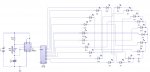
DAC command. Also, IMHO the LEDs are not strictly being driven as a Chalieplex, which could drive 12 LEDs from 4 output pins (even with brightness control, at least via software/multiplexing). However, alternate LEDs must be wired Anode/Cathode to the "PWM" Output so that one increases in brightness whilst the adjacent LED reduces.
Incidentally, since the aim is to produce a "rotating" result, I can't decide if the effect might be any better if the PWM sequence was sinusoidal (which could be easily implemented via a lookup table) rather than a simple Ramp Up/Dowm. It might depend on the particular LEDs' Beam-Width/Pattern?
Cheers, Alan.