LCD/LED/OLED assorted displays 'lucky bags' at Maplin 1 (N01CG) Kemo Electronic S043

nick12ab

Senior Member
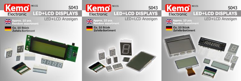
This is the first in a series of blog entries which cover the displays included in the Kemo Electronic S043 lucky bag sold at Maplin and describes the use of them. The series went under massive reorganisation in 2016 with the addition of new displays plus a new overview picture.
Scroll down for the display index.

This lucky bag typically costs £4.99 and contains 10 assorted displays. Each bag comes with a variety of different displays with balanced distribution, and generally a bag 2-3 large displays, 2-3 medium displays and 4-6 small displays, so you won't find one bag containing entirely HD44780-compatible LCDs and another containing 7-segment displays only. I wouldn't recommend just buying them on the website as you don't get to see what's in the bag unlike in store. The displays aren't individually packaged and they have the potential to damage each other in the packaging so you'll want to check for that before you buy.


Index
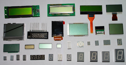

Click to view full size image.
Image is oversaturated to highlight the different colours of the LCDs.

Displays are numbered below in row-column format e.g. 4-1 is the tiny 7-segment display in the bottom left corner.
Blog entries in Blog Entry column:
1 - this one
2 - Click Here
3 - Click Here
Nothing - the display is not covered because there's nothing to say about it
Users should test all LED displays before building a stripboard/PCB circuit for them.


NumberNameDescription
CA = Common Anode, CC = Common Cathode
Size (mm)
d = diagonal
Illumination ColourStatus - PICAXEBlog entry
1-1AMPY2001-11HD44780-compatible LCD: 16x1 + symbols67 dReflective - Yellow-GreenWorking3
1-2LXC1615ETRHD44780-compatible LCD: 16x166 dReflective - GreyWorking3
1-308580002-N08YBN00HD44780-compatible LCD: 16x264 dReflective - GreenWorking3
1-4UMSH-7519AN-5FGraphic LCD: unknown resolution50 dReflective - GreyNo - Unattempted2
2-1TM12880CCCWUGNA-B-2BGraphic LCD: 128x8060 dTransflective - GreyNo - Controller unknown2
2-2HNM-05SS62TBare glass VFD: 4 digit 7-segment10Bluey greenWorking2
2-3PH128160T-066-L03QTFT LCD: 128x16045 dNo - Mine came smashed
2-4DGL-0401YG-4EHBare glass LCD: 3 digit 7-segment, 18 pins52 dTransflective - Grey
Yellow-green backlight
Working - not with PICAXE2
2-5OS096016PP08MB2B10OLED: 96x1625 dBlueWorking3
2-6Bare glass LCD: 17 digits, 60 elastomeric contacts50 dReflective - GreyNo - Unattempted2
3-1Bare glass LCD: 4 digit 7-segment, 15 pins50 dReflective - GreyWorking - not with PICAXE3
3-2Bare glass LCD: 6 digit, 7-segment, 26 elastomeric contacts29 dReflective - Brown-GreyNo - Unattempted
3-3Bare glass LCD: 4 digit, 7-segment, 19 elastomeric contacts38 dReflective - GreyNo - Unattempted
3-4Bare glass LCD: 5 digit 7-segment, 26 elastomeric contacts15 dReflective - GreyNo - Unattempted2
3-5LTL-2685HRLED block display: 8 dice20x10Super RedWorking
3-6SB1717-12LED segment display: 6 green + 2 red dice, CA15Green+Bright RedWorking2
3-7SS335SUR7-seg LED: Surface Mount, CC7Super RedWorking
3-8KCSA39-1057-seg LED: Surface Mount, CA10Super RedWorking
3-9KCDC04-1057-seg LED: 2 digit, Surface Mount, CC10SuperRedWorking
3-10SS512UYWA7-seg LED: Surface Mount, CA14YellowWorking
4-1TDSR076017-seg LED: staggered pins, CA7Super RedWorking
4-2LTS-3361JD7-segLED: CA8Super RedWorking
4-3HDSP-C3L17-seg LED: CA9OrangeWorking
4-4HDSP-C3L37-seg LED: CC9OrangeWorking
4-5TDCR1050M7-seg LED: 4 digit, requires multiplexing, CA10Super RedWorking
4-6TDSL5050G7-seg LED: CA13Bright redWorking
4-77-seg LED: CA13"High efficiency" redWorking
4-8HDSP-H1017-seg LED: CA14.2Bright RedWorking
4-9LC6321-217-seg LED: All segments have 2 LEDs in series, left DP, CC16GreenWorking
4-10HDSP-C8E17-seg LED: All segments have one LED, CA20Bright RedWorking
4-10HDSP-C8L17-seg LED: All segments have one LED, CA20OrangeWorking
4-11HDSP-42017-seg LED: All segmentshave one LED, CA20YellowWorking
4-12HDSP-C1G37-seg LED: All segments have two LEDs except DP, CC25GreenWorking
MD216-01HD44780-compatible LCD: 16x267 dGreenWorking3
WAYTON M.I.T PC-1206E2KS0108B-compatible Graphic LCD: 128x6464 dGreenWorking3

2-5 OLED Display (OS96016PP08MB2B10) has been moved to blog entry 3 (comments section).
 

nick12ab

Senior Member
Found out how to add an external contrast control - remove R13 from the board, then run a wire from the conveniently marked VLCD pad to pin 18 on the connector which is normally unused.
 

Anobium

Senior Member
How did you progress with the code for the LCD display?

But, the components are still very good value for money.
 

nick12ab

Senior Member
Anobium;bt279 said:
How did you progress with the code for the LCD display?
  • The HD44780-compatible LCD pinout is shown in the leaflet provided with the displays which you can see by clicking on the first picture in the blog entry. The top row is normal 5x7 characters and works just like on a normal 16x2 LCD (i.e. they are all consecutive one one line rather than divided into two groups like on 16x1 displays) and the bottom row of symbols are activated as described in the blog entry.
  • The LCD that requires elastomeric connectors (and which I forgot to include in the photograph) - I haven't attempted to use that yet.
  • The little OLED displays - the eBay adapter board arrived and I got a display working and I've made a DS1307 clock demo that has so far been running for over two weeks off the same pair of AA rechargeables on the minimum brightness setting. I will make a schematic and post the example in Finished User PICAXE Projects soon. The OLED is definitely blue.
If I haven't answered your question properly, ask again and give more detail.
 

Anobium

Senior Member
My progress. I had a thought... use the AXE133 firmware and adapt that. The normal commands all work to line 1 of the device. This includes position cursor control etc.

I am trying to figure out the bottom line addressing. I have contacted a guy on another forum to see if he has any insights.

@nick12ab - can you explain your contrast control a little more.

Anobium
 

Anobium

Senior Member
Lots of questions. :D


Can you post the LCD that requires elastomeric connector? I am not sure I got that device.


Can you share the the eBay adapter board ? Would you post the URL to the listing?

The large HD44780 LCD. I have the top line operational but I cannot address the symbols. Any hints please..?
 

nick12ab

Senior Member
Anobium;bt283 said:
Can you post the LCD that requires elastomeric connector? I am not sure I got that device.
I will take a picture and add it to the blog entry shortly.

Anobium;bt282 said:
can you explain your contrast control a little more.
I've taken a picture to show you and I will add it to the blog entry shortly.

Anobium;bt283 said:
Can you share the the eBay adapter board ? Would you post the URL to the listing?
http://www.ebay.co.uk/itm/120688893594

I mounted the OLED on the PCB with the PCB having its through-hole connectors at the bottom and the OLED's connector soldered to the 0.7 pads with the screen facing down and overhanging the top of the PCB. Once it had been soldered, I then folded the display over so that it faced upwards and blu-tacked it to the flex.

Anobium;bt283 said:
The large HD44780 LCD. I have the top line operational but I cannot address the symbols. Any hints please..?
The symbols start with address 192, just like it would do if there were actual character places there.
 

Anobium

Senior Member
Well done on the OLED!!! I must place order eBay. I will wait for your code - well done.


Here is the table of information that I have created this evening. I am using the standard AXE133 code as the Picaxe interface to the LCD, 8-bit. (I know think I code use 4-bit by pulling D0-D3 to ground which I failed to do yesterday - but, it ho hum).

I think the symbols are in two pairs, addressed as you say by the characters but the addressing is as shown in the routines below.

So, the first two are address @ 254,193, "D"|"J"|"E"|" " The space clears the chars. They run in two step until 199 then 1, then back to two step... odd. But, this code does seems to work.


Do you think this is stable?


' I have 08m2 to 18m2 to LCD.

Code:
#picaxe 08m2
#no_data
pause 2000


	serout C.2,N2400,(254,1)
		pause 100

		
		serout C.2,N2400,(254,128)
		pause 100
		serout C.2,N2400,(#b1, ": Testing")
		pause 100

		' First two chars
		' L1
		'serout C.2,N2400,(254,193,"D")
		' L2
		' serout C.2,N2400,(254,193,"J")
		' both
		' serout C.2,N2400,(254,193,"E")
		
		' Second two chars
		' L3
		' serout C.2,N2400,(254,195,"D")
		' kw
		' serout C.2,N2400,(254,195,"J")
		'  both
		' serout C.2,N2400,(254,195,"E")
		
		' Third two chars
		' h
		' serout C.2,N2400,(254,197,"D")
		' kvar
		' serout C.2,N2400,(254,197,"J")
		'  both
		' serout C.2,N2400,(254,197,"E")

		' Forth two chars
		' h
		' serout C.2,N2400,(254,199,"D")
		' (Down chevron)!
		' serout C.2,N2400,(254,199,"J")
		'  both
		' serout C.2,N2400,(254,199,"E")
		
		' Fifth two chars
		' Circle
		' serout C.2,N2400,(254,200,"D")
		' Square
		' serout C.2,N2400,(254,200,"J")
		'  both
		' serout C.2,N2400,(254,200,"E")

		' sixth two chars
		' NE Quad
		' serout C.2,N2400,(254,202,"D")
		' NW Quad
		' serout C.2,N2400,(254,202,"J")
		'  both
		' serout C.2,N2400,(254,202,"E")


		' seventh two chars
		' SW Quad
		' serout C.2,N2400,(254,204,"I")
		' SE Quad
		' serout C.2,N2400,(254,204,"H")
		'  both
		' serout C.2,N2400,(254,204,"E")

		' last two chars
		'  both = house
		' serout C.2,N2400,(254,206,"E")
		

do 
			' NE Quad
			 serout C.2,N2400,(254,202,"D")
			 pause 250
			
			' NW Quad
			 serout C.2,N2400,(254,202,"J")
			pause 250

			' blank
			 serout C.2,N2400,(254,202," ")

			 
			' SW Quad
			 serout C.2,N2400,(254,204,"I")
			pause 250

			' SE Quad
			 serout C.2,N2400,(254,204,"H")
			pause 250

			' blank
			 serout C.2,N2400,(254,204," ")
			
loop
 

nick12ab

Senior Member
Anobium;bt285 said:
So, the first two are address @ 254,193, "D"|"J"|"E"|" " The space clears the chars. They run in two step until 199 then 1, then back to two step... odd. But, this code does seems to work.


Do you think this is stable?
I know that the symbols weren't in a logical order. I disassembled my test circuit a while ago but I might get around to finding out the addresses for each part.

Anyway, OLED clock demo now posted.
 

nick12ab

Senior Member
Anobium;bt285 said:
Do you think this is stable?
I cannot see anything wrong with that code. I will be reassembling a test circuit to find out the exact address of each symbol on the LCD.
 

nick12ab

Senior Member
Anobium;bt283 said:
Can you post the LCD that requires elastomeric connector? I am not sure I got that device.
Did you get the LCD that requires elastomeric connector, a surface mount 7 segment display or something else?

Anobium;bt285 said:
Well done on the OLED!!! I must place order eBay. I will wait for your code - well done.
Have your adapter boards arrived yet?
 

alecw

New Member
Hi,

Thanks for the helpful article. I've got the LCD working with my Arduino (LEDs and button too), and I'm wondering what I could do with the OLED displays. Do you think that they might fit into a breakout board like this one?

http://proto-pic.co.uk/ffc-breakout-board/

Soldering anything onto those little tabs is a bit beyond my ability!

Thanks,
alec
 

nick12ab

Senior Member
alecw;bt311 said:
and I'm wondering what I could do with the OLED displays. Do you think that they might fit into a breakout board like this one?

http://proto-pic.co.uk/ffc-breakout-board/
You can't use that breakout board because it does not have enough pins and the tab is too wide to fit in that.

Soldering it is not as difficult as it looks - purchase a breakout board like the one in my pictures, apply solder to the appropriate pitch connector, line up the OLED with the connector then apply solder to a few pins at a time while gently pressing down with the soldering iron.
 

Anobium

Senior Member
I have the connector/adapter off Ebay. A great piece of advice as I would never have been able to locate the adaptor.

Currently travelling so no time for the project until I get back soon. I test align the connectors and they are accurately aligned.

Thanks for helping. I just to stop travelling for work so I can get back to my project. :)
 

PaulRB

Senior Member
All, just checked out my local Maplin (Leeds). One pack left on sale. Connectors on both oled displays clearly knackered. There is another Maplin in Leeds and others in Wakefield & Sheffield, might check them out.

Paul
 

nick12ab

Senior Member
PaulRB;bt322 said:
All, just checked out my local Maplin (Leeds). One pack left on sale. Connectors on both oled displays clearly knackered.
You should have tried to get a discount. Say that the OLEDs are the most valuable parts in the bag and try to get £2 off :) (well, the only component that's possibly more valuable than the OLEDs is the AMPY 2001-11 LCD)

The worst they can do is say "No".
 

PaulRB

Senior Member
To be honest, the oleds were the most interesting to me, because of the small size and i2c interface. I already have a few 16x2 lcd cheap from china.
 

PaulRB

Senior Member
Managed to find a pack in the other Leeds Maplin with oled connectors in decent looking condition. Have also ordred some dip adaptors from China on eBay. I bought a pack of 10 adaptors so hopefully will have a few available to sell or swap eventually.

Nick, would you mind describing in more detail the easiest way to solder these? I've never tackled smd devices before. Cheers.
 

nick12ab

Senior Member
PaulRB;bt325 said:
Nick, would you mind describing in more detail the easiest way to solder these? I've never tackled smd devices before. Cheers.
First put leaded solder on the contacts on the 0.7 connector. Do this by feeding the solder into the tip of the soldering iron while running the tip from one end of the connector to the other. Fresh solder should not create any solder bridges between each pad - if this happens add more solder. Minimize the time that the soldering iron is melting the solder for.

Hold the OS96016PP08MB2B10 OLED with the display facing down and the IC on the tab facing upwards. Line up the connector with the connector on the PCB (positioned like this here) and solder the pins in small groups by gently pressing down on the connector with the soldering iron tip, adding extra solder if necessary. Once soldered, fold the display part over so that it faces upwards and stick in place with blu tack. Now solder the headers to the provided holes.

P.S. Can you tell me what 10 items you got in your lucky bag? The contents does vary slightly between lucky bags.
 

PaulRB

Senior Member
Got a photo of my pack here but can't attach it. Unlike posting in the forum, there's only the option to add a link to a photo.

Anyway, I have the ampy lcd, the square bare lcd, 2 oleds, the 4 digit clock led, a 2 digit led, a single digit led, 2 tiny single digit leds and a bar-graph led.

Thanks for the soldering instructions.
 
Last edited:

PaulRB

Senior Member
I haven't even tried with mine yet. I have the adaptors, the ones you suggested. I'm not looking forward to the soldering despite your encouragement. I struggle sometimes with 0.1" components, as you may have seen on the main forum the other day. Wondering about investing in a temp controlled iron, a flux pen and a wider selection of bits. Might put them on my wish list, although my birthday's a way off yet.
 

nick12ab

Senior Member
PaulRB;bt350 said:
I haven't even tried with mine yet. I have the adaptors, the ones you suggested. I'm not looking forward to the soldering despite your encouragement. I struggle sometimes with 0.1" components, as you may have seen on the main forum the other day. Wondering about investing in a temp controlled iron, a flux pen and a wider selection of bits. Might put them on my wish list, although my birthday's a way off yet.
I soldered mine with a normal Antex CS18 soldering iron with the normal 'one flat side' tip, with leaded solder. Making sure you have decent lighting will help you align the connector for soldering.
 

PaulRB

Senior Member
nick12ab;bt326 said:
First put leaded solder on the contacts on the 0.7 connector. Do this by feeding the solder into the tip of the soldering iron while running the tip from one end of the connector to the other. Fresh solder should not create any solder bridges between each pad - if this happens add more solder. Minimize the time that the soldering iron is melting the solder for.

Hold the OS96016PP08MB2B10 OLED with the display facing down and the IC on the tab facing upwards. Line up the connector with the connector on the PCB (positioned like this here) and solder the pins in small groups by gently pressing down on the connector with the soldering iron tip, adding extra solder if necessary. Once soldered, fold the display part over so that it faces upwards and stick in place with blu tack. Now solder the headers to the provided holes.
Well, that was tricky, and unfortunately, I think I've got it wrong. Nick, could you have a look please and see if I can salvage the situation?

Mistakes:
1. Despite counting the connections on the OLED several times, I convinced myself there were 30. Looking at the closeup images I took, I now see 31...
2. I was aiming for the leftmost connectors on the adaptor, but it looks like I missed the first one and have soldered to the second leftmost onwards.
3. Avoiding solder bridges on the connectors took alot of re-touching with the iron. Do you think I did well enough in terms of quality?

Positives:
My breadboard adaptor looks very neat compared to other efforts. I made it with a tiny piece of tri-pad board. Shame I didn't make it 32 connectors...

http://www.picaxeforum.co.uk/showthread.php?23799&p=239701#post239701

Thanks,

Paul
 
Last edited by a moderator:

nick12ab

Senior Member
PaulRB;bt355 said:
Well, that was tricky, and unfortunately, I think I've got it wrong. Nick, could you have a look please and see if I can salvage the situation?

Mistakes:
1. Despite counting the connections on the OLED several times, I convinced myself there were 30. Looking at the closeup images I took, I now see 31...
2. I was aiming for the leftmost connectors on the adaptor, but it looks like I missed the first one and have soldered to the second leftmost onwards.
3. Avoiding solder bridges on the connectors took alot of re-touching with the iron. Do you think I did well enough in terms of quality?
It's not a bad attempt. I'd say it's a good thing you missed the first PCB pad because that now means that the pins are in the same order that they are on my own attempt. Just add an LED offcut for the OLED pad that you missed.
 

nick12ab

Senior Member
Unfortunately I couldn't fit this in the blog entry because of a 10000 character limit.

Kemo Electronic has updated their datasheet and it now shows:
  • Four 7-segment displays
  • The tiny LCD that requires elastomeric connectors
  • OS96016PP08MB2B10 OLED Display
  • [NEW] Long LCD that requires elastomeric connectors
  • [NEW] 4-digit 7-segment VFD module (looks like it could be from a microwave)
  • [NEW] Chip on glass LCD module
  • [NEW] LCD with metal frame and backlight - it could be one of those mobile phone screens which have previously been documented on this forum by others
The amount of data for displays in the datasheet is even more dire than before (only has pinouts for three 7-segment displays and the OS96016PP08MB2B10 OLED). Fortunately the chip on glass module quite obviously has markings on the back so hopefully it won't be some custom part that is impossible to find data for.

Update on 28/11/2013:
I went to a Maplin and they didn't have any of these new bags - the two bags it had contained the large LCD with pins which requires multiplexing.

Update on 10/12/2013:
I went into the same Maplin again and they still don't have any of the new bags.

Update on 04/01/2014:
The same Maplin continues to only have bags containing the large LCD that requires multiplexing which isn't very useful. This means it takes over a month for the new displays shown in the online pdf to arrive in stores. I didn't keep track of how long after the pdf changed from having the AMPY2001-11 LCD to having the bare glass with pins those bags appeared in stores so I can't predict when the new bags will turn up but even if I did know it's likely to be much longer for the new bags now because the contents of the bag that is to be replaced is less desirable compared with the bag before that.

Update on 19/01/2014:
I went into a different Maplin and the only bag it had was one with the large LCD that requires multiplexing, the 7 segment LED displays, an OLED, etc.

Update on 02/02/2014:
This different Maplin continues to not have the new bags.

Update on 10/02/2014:
The first Maplin continues to not have the new bags.

Update on 27/03/2014:
The first Maplin continues to not have the new bags.

Update on 10/04/2014:
The first Maplin continues to not have the new bags. Almost five months since I first saw the updated PDF. Posting this must have harmed sales of the previous bags.

Update on 30/04/2014:
The first Maplin had a new bag! Since Kemo obtain surplus stuff, all the new entrants are custom parts that you can't find data for. Not yet anyway.
  • The LCD with the metal frame appears to be a graphic LCD of resolution 128x80 and is chip on glass. A Chinese website reveals what it is from.
  • The smaller COG LCD, marked UMSH-7519AN-5F, also appears to be custom (which comes as a surprise). The outer few mm of the viewing area is lighter than the rest of the LCD which suggests it could be a graphic LCD. A distinguishing feature of the flex is that it has two pins at one end that aren't connected to the module so if a standard module with a flex with the same feature and pin count can be found chances are it has the same pinout.
  • Long LCD that requires elastomeric connectors - 4 digit 7-segment, reflective. The pitch of the connections is quite large (but not 1") but there are sufficient connections to suggest that it is static drive. A dead 16x2 HD44780-compatible module can be used as a source for elastomeric connectors however the bare glass LCD here is more than half the length of a normal size 16x2 module so it would only provide enough for one display.
  • VFD - this is also a custom part however its pinout can be clearly seen from the back. Voltages will have to be found by guesswork.
It seems that when it comes to finding pinout diagrams, Kemo do really try as anything that has a pinout on the internet has one in their PDF - even the AMPY2001-11 which has a diagram based on one from an obscure Italian website.
 
Last edited:

nick12ab

Senior Member
The VFD (SAMSUNG SSED HNM-05SS62T) is working in a PICAXE-controlled multiplexed circuit!

For details on the VFD glass itself, see the other blog entry linked above.

In terms of power consumption for the anode voltage with most of the segments lit, it is around 7mA at 20V (the minimum required for a good display) and 20mA at 45V. When comparing this to an LED display keep in mind that the voltages are higher so much more power is being used compared to 20mA at 5V. For best display brightness more volts are better.


For driving the anodes and grids, PNP transistors with bases driven by NPN transistors via 10k resistors are used. Eight pairs are used for the anodes and four for the grids. Because only the dot from the middle grid is used in the above demo and it has an independent pin, the middle grid (grid 3) is connected to grid 2 and the dot is connected to the remaining pin on the 8-bit port used to drive the anodes (through the transistors). The grids must be pulled down to 0V when not activated - use resistors not less than 10k because rather large currents can flow when the associated PNP transistor is turned on and 50V is put across the resistor!

Ideally transistor arrays in DIP packages should be used since the 12 pairs of transistors required take up almost an entire breadboard.

Note: This OLED (or ones very similar) can be found in Indesit Company cookers.
 
Last edited:

nick12ab

Senior Member
New year, no new bag.

However by looking at the dates in the PDF Document Properties, we can see when Kemo updated their goody bags. The dates are as follows:
BagDate Created/ModifiedDays since previous
Bag with AMPY2001-1106.07.2012
Bag with DGL-0401YG-4EH11.04.2013279
Bag with VFD19.11.2013222
The average difference between bag releases is 250 days. Based on that the new bag was due to be released on 27.07.2014, so it is well overdue. Hopefully a new one will be released soon with more interesting components.
 
Top