Inputs over 5V

cpedw

Senior Member
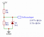
I'm planning a monitor/alarm module for a diesel engine with nominal 12V alternator and lead-acid battery. Some digital inputs to a 14M2 will be at the alternator/battery voltage which could conceivably be between 10 or 11 and 15V.

Is this from post 4 in this thread be the sort of circuit that is best suited to deal with this sort of voltage?
25844
 

hippy

Ex-Staff (retired)
That can and will work but it would be recommended to use a traditional resistor divider arrangement -
Code:
          \
~12V >---O O----.
               .|.
               |_|
                |   
                }----> 0V-5V
               .|.
               |_|
                |
0V -------------^----- 0V
I'm not sure what the resistor values would be and it would depend on what the actual '~12V' value is.

As long as the output voltage is above 2V ( 4V for a Schmitt input ) it should be fine and that will allow the input voltage a degree of overhead for whatever nominal input voltage the resistor used are specified for.


You shouldn't need an external clamping diode when the voltage on the pin is below the 5V supply rail.
 

cpedw

Senior Member
I'm not sure what the resistor values would be and it would depend on what the actual '~12V' value is.

As long as the output voltage is above 2V ...
I had thought the minimum voltage for Vih was more than 2V (should have looked it up!). The 'actual 12V' can be 10-15V so I can happily arrange the pin voltage to be 3.3-5V or a bit less for safety with a voltage divider. Thanks.
 

1968neil

Senior Member
The divider below should give you what you need and by adding the 5v1 zener you'll protect the input if you get spikes above the 5v supply voltage.
Personally i add them to input circuits with anything that "Might" go over, it's just a good precaution and they cost pennies.
 

Attachments

AllyCat

Senior Member
Hi,

The Zener diode is fine if you are using the input as a Digital Input, but is not a good idea if using it as an ADC input with the default Vcc Reference voltage (it should be ok if using the FVR2048 and maybe FVR4096 references). The issue is that a 5V1 Zener will normally have a +/- 5% tolerance (i.e. 4.8 to 5.4 volts) and this is calibrated with 5 mA flowing through the diode.

Normal Zener diodes rated below about 7.5 volts don't have a sharp "knee" so will "leak away" some current even below the nominal Reference Voltage and give an incorrect divider ratio. Post #79 HERE is a post where I gave a more detailed description and showed some typical data.

Cheers, Alan.
 

mortifyu

New Member
And for those of you playing along at home, to further add to Alan's comment... To provide protection when using an ADC input and NOT have any influence on the divider ratio, a rail to rail op-amp could be added to the circuit and used as a 'buffer' like shown in this diagram. In this configuration, the op-amp output precisely tracks the voltage divider anywhere from zero up to the maximum of the PICAXE/OP-AMP supply rail and thus it is not possible for the op-amp output/ADC input to ever exceed the supply rail maximum. Perhaps a little more advanced than using a simple zener, but nonetheless is quite an effective and non-intrusive protection solution for ADC applications.

R1 & R2 form the voltage divider as noted earlier in this thread.

OPAMP-ADC_INPUT-PROTECT.png


Regards,
Mort.
 
Top