How do you know when your IR sensor fried?
- Thread starter HarryLee
- Start date
Ah... that makes sense. You'll need to use READADC or READADC10 commands to help you here. Start with a really simple bit of code, just read the input and output it to a terminal. Then loop back again, preferably with a pause so you don't get a constant stream of data.
Good luck.
Good luck.
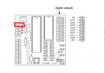
I have never actually used the picaxe board you have or even know what connections on the board go to what pins, so i am unable to comment on your connections to the board.
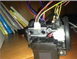
The photo of the circuit board is next to useless as it dont show clearly which wires are connected to what pins.
The sensor wiring has this colour code with how you have it wired
Yellow = voltage out........... this connects to any ADC pin on the picaxe.
Black = ground ................. this connects to ground on the picaxe board
Red = 5v+ .................. this connects to the 5v+ supply on the picaxe board
Then a simple test program like this should show if its all working.
You will need to replace pin# with the actual ADC pin number that you connect the yellow wire of the sensor to.
With the programming cable still connected after loading the code to the picaxe, you should see the value in variable b0 change up and down as you bring a object towards and away from the sensor.
The photo of the circuit board is next to useless as it dont show clearly which wires are connected to what pins.
The sensor wiring has this colour code with how you have it wired
Yellow = voltage out........... this connects to any ADC pin on the picaxe.
Black = ground ................. this connects to ground on the picaxe board
Red = 5v+ .................. this connects to the 5v+ supply on the picaxe board
Then a simple test program like this should show if its all working.
Code:
main:

Readadc [B]pin#[/B], b0

debug
pause 200
goto mainWith the programming cable still connected after loading the code to the picaxe, you should see the value in variable b0 change up and down as you bring a object towards and away from the sensor.
Before you dive into code to drive your motors, have you tested if the sensor is working first.
One thing about producing code to run several different functions it to do little tests of each device first to workout if its working, and how you control it in code.
Then jump to the next level and start to develop the code to run all the devices.
It is the far quicker way to learn and far quicker in the log run of getting the project to work.
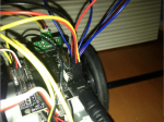
You are totally right, I found the problem, that is my sensor connection's problem, 3 of the wires that hook on the sensor had been combined into one jumper cable with 3 pins on it, that means I cannot change the sequences of the pins (V G Vout), so that's why I connected wrong on the project board, because the project board required the sequence of Black, Yellow and Red, but as you can see in #45, mine was Black Red and Yellow because the wires are all in one, so I have to cut and solder it.
A little hint.
Often with the header pin connectors on the end of wires, with a little care and a small screwdriver you can pop the wires and terminal end, out of the plastic housing, then slide them back in the housing in the required order, without the need to cut and solder anything.
Often with the header pin connectors on the end of wires, with a little care and a small screwdriver you can pop the wires and terminal end, out of the plastic housing, then slide them back in the housing in the required order, without the need to cut and solder anything.