How difficult would this be?
- Thread starter chigley
- Start date
BeanieBots
Moderator
Putting it on the top power rails would be better than nothing.
If you had DIRECT lines from the top rails to the PICAXE it would be better.
You could put direct to the PICAXE pins on the underside of the board. That's how I often do mine. If you have open frame type sockets then decoupling caps can be made to fit within the socket itself.
If you had DIRECT lines from the top rails to the PICAXE it would be better.
You could put direct to the PICAXE pins on the underside of the board. That's how I often do mine. If you have open frame type sockets then decoupling caps can be made to fit within the socket itself.
I'd say today's been quite successful ")
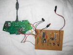
Here's a photo of how my board looks so far:

Unfortunately I've dropped unlucky and the red LED appears to be 'dud'. My multimeter is reading 4.5v across the LED's legs but it's not lighting. That's the only problem I've come up against so far though - the 18X programmed first time. I'm not convinced that the transistors are switching either but I'll test that fully at a later date.
Unfortunately I've got a busy week this week, so I might have to put this on the side until next week. Next things I'll do is put the 4066 and EEPROM on the board; replace the red LED and put the capacitor over the PICAXEs power pins. Then I'll interface it with the controller (shouldn't be too hard, as long as the transistors are switching).
After I have it interfacing with the controller I need to read up on EEPROM organisation to store all of the song data!
Here's a photo of how my board looks so far:
Unfortunately I've dropped unlucky and the red LED appears to be 'dud'. My multimeter is reading 4.5v across the LED's legs but it's not lighting. That's the only problem I've come up against so far though - the 18X programmed first time. I'm not convinced that the transistors are switching either but I'll test that fully at a later date.
Unfortunately I've got a busy week this week, so I might have to put this on the side until next week. Next things I'll do is put the 4066 and EEPROM on the board; replace the red LED and put the capacitor over the PICAXEs power pins. Then I'll interface it with the controller (shouldn't be too hard, as long as the transistors are switching).
After I have it interfacing with the controller I need to read up on EEPROM organisation to store all of the song data!
SilentScreamer
Senior Member
I can't comment for your LEDs but that would blow most of mine.Unfortunately I've dropped unlucky and the red LED appears to be 'dud'. My multimeter is reading 4.5v across the LED's legs but it's not lighting.
I just replaced the LED with a different one (wrong colour, but it was just for testing purposes) and it works fine. Guess I'm just very unlucky!
@SilentScreamer - ignore the faulty multimeter readings. My meter is horrendously bad and cheap. It's on my list of things to buy!
@SilentScreamer - ignore the faulty multimeter readings. My meter is horrendously bad and cheap. It's on my list of things to buy!
...with an open-circuit failed LED, measuring 4.5V across it with a multimeter when the PICAXE output is high would seem entirely normal - you are essentially measuring between the PICAXE output and ground. The 330R resistor will have no perceptible effect. Also...
...it doesn't mean it will blow the LED when you connect it.
...it doesn't sound like a faulty multimeter.
...it doesn't mean it will blow the LED when you connect it.
...it doesn't sound like a faulty multimeter.
Haha maybe not in this case then, but overall it's pretty crap...it doesn't sound like a faulty multimeter.
I'm just glad there isn't a major flaw in my stripboard design.
BeanieBots
Moderator
An OC LED is quite rare even after severe abuse but is possible.
More probably in the wrong way round!
Anyway, glad you've got the essentials working and you are taking the right approach. One step at a time.
More probably in the wrong way round!
Anyway, glad you've got the essentials working and you are taking the right approach. One step at a time.
Nah it wasn't in the wrong way round either; must have just been dead (I'm having one of those weeks so it wouldn't suprise me!), as other LEDs work fine in the same spot.An OC LED is quite rare even after severe abuse but is possible.
More probably in the wrong way round!
Anyway, glad you've got the essentials working and you are taking the right approach. One step at a time.
I'm having to put this on the side until Tuesday now. Gives me some time to think about the programming though!
Hi again,
Just measured the load current to average at around 700μA.
BeanieBots said to use the lowest hFE value, that's 150. So I divide my 700μA by 150 to get a required base current of 4.7μA, right? Then I double this to ensure full switch on, so roughly 10μA.
Then it's just Ohm's law to work out the resistance required to give the base current. So R = V/I = 5/0.00001 = 500k!?
That can't be right, can it? Where've I gone wrong? I never knew transistors were so complicated!
Charlie
BeanieBots
Moderator
You got it spot on. Not so complicated was it?
The reason you ended up with such a high value is because your hfe is quite high and your load is very low. (you should use peek not average).
The nearest prefered value would be 470k.
Now for the complicated bit!
470k is quite a high value and could be prone to noise and stray currents so you might want to consider comming down quite a bit.
If your app is battery operated, you might like to keep it fairly high, otherwise come down quite a lot for noise immunity.
I'd suggest a value of 47k as a good compromise.
You also now KNOW that the transistor will turn fully for your load current.
You also KNOW that you are not wasteing any base current.
If this was for a more complex ultra fast timing critical purpose (<10nS), the original value of around 470k would be needed to avoid excess saturation and care taken about noise/stray currents.
Now you know how to calculate base resistor values. Well done.
As an excercise, try it for the popular 2N3055 switching on a motor that pulls say 5A. Can you spot the trap?
“So R = V/I = 5/0.00001”
Almost. You forgot to subtract the Vbe on the base side. (No current flows into the base until the base voltage gets higher than a diode-drop above the emitter). So the 5 in the above calculation becomes 4.3 (For a 0.7 Vbe and a grounded emitter).
IE: R= 4.3/0.00001
It will make no practical difference for this particular application, but might in others. You should get used to including it.
BeanieBots
Moderator
Good point Boriz.
As you say, no big deal here but should be included for completeness.
As you say, no big deal here but should be included for completeness.
Hi again! Just an update.
I now have the PICAXE 18X fully interfaced with the Xbox 360 controller - all 5 fret outputs are working! I had to make some on-the-fly additions to my circuit board to properly interface with the frets I'm using transistors for. You'll also notice that I didn't bother with the 47k base resistors, as it's working with 4k7s at the moment and I'm not bothered about the wasted current! I've also added in the EEPROM and have been able to successfully write to and read from it using the PICAXE.
Here's a photo of the bot so far:

The next step will be writing the note chart for a song to the EEPROM in a format which the PICAXE can read, parse and then output whilst playing the song. I'm currently in the process of trying to extract the note charts in a text format from the Guitar Hero game disk, to save me from manually writing the charts for each song. Once I've managed to extract the charts from the disk I'll try to work out what the best solution is to save the charts on the EEPROM.
Thanks to all who've helped so far!
Charlie
I’m not criticising. You’ve obviously done the research, put the work in and built your project. Good for you. But, I have to ask, what’s the point? I mean, what’s it for?
So far as I understand it, Guitar hero is a game that challenges the user to operate the buttons in a well timed sequence. Once this is automated, it defeats the whole object of the game. It can essentially ‘play itself’. What am I missing?
So far as I understand it, Guitar hero is a game that challenges the user to operate the buttons in a well timed sequence. Once this is automated, it defeats the whole object of the game. It can essentially ‘play itself’. What am I missing?
I wanted to think of a project I could do over Summer which wasn't too challenging that I'd give up early on, but would require me to learn and use new things. In my opinion, this project meets these criteria - although the hardest part is probably yet to come!I’m not criticising. You’ve obviously done the research, put the work in and built your project. Good for you. But, I have to ask, what’s the point? I mean, what’s it for?
So far as I understand it, Guitar hero is a game that challenges the user to operate the buttons in a well timed sequence. Once this is automated, it defeats the whole object of the game. It can essentially ‘play itself’. What am I missing?
It may seem pointless to other people, but I still think it'll be a cool thing to have when it's done
Even if you think it is pointless, the knowledge I'll gain from carrying out this project will definitely make it worth doing, don't you think?@Charlie.
It's excellent that you've provided feedback.
Many don't. :-(
Just a thought on photo's.
Rather than paste/embed a 2Mbyte+ pic,
from a third party (Imageshack),
1. Take photo.
2. Use a Photo-editor program to produce a "manageable" jpg.
3. Use the "Manage Attachments" option in Reply
I used Adobe Elements, but, there are many alternatives.
e
Attachments
-
 208.5 KB Views: 9
Andrew Cowan
Senior Member
I use paint.
For some reason, opening a large (~2MB) file, changing one pixel, then saving it reduces the file size to about 300kb.
Simple and easy.
A
For some reason, opening a large (~2MB) file, changing one pixel, then saving it reduces the file size to about 300kb.
Simple and easy.
A
SilentScreamer
Senior Member
Are you saving that as an 8 bit image rather than 24 bit or 32 bit?
I've now successfully managed to extract note charts from the Guitar Hero game. I then wrote an application on my computer to parse these charts and output the corresponding PICAXE BASIC code (it wouldn't all fit on the PICAXE 18X, so I just copied/pasted the first 1,000 lines or so, just to test if the timing was correct.) When I play the songs with the bot, I get a streak of about 100 notes, but there are then still some errors in the timing. I'll iron out these kinks later on.
I decided that the next step was to try to save an entire song onto the EEPROM, such that it can be read into the PICAXE whilst the song is being outputted. As expected, I'm having some difficulties! This is the format I'm trying:
The first four ds represent the delay in milliseconds to be waited before playing the note(s). The letters g to o represent the fret states (either 0 or 1). The last four letter ds represent the duration for the notes to be held in milliseconds before being released. The delays will never be more than 9999ms. This sequence is then repeated, and will be read into the PICAXE in a loop.
I used the following code to write to the EEPROM:
I read about the page write buffer on page 3 of the I2C manual, hence writing to every 16th byte.
I think I've already gone wrong though. I don't think I need an entire byte for the five fret states, as they are only a bit each. Totally lost - please advise!
I decided that the next step was to try to save an entire song onto the EEPROM, such that it can be read into the PICAXE whilst the song is being outputted. As expected, I'm having some difficulties! This is the format I'm trying:
Code:
ddddgryboddddI used the following code to write to the EEPROM:
Code:
low 0 ' write protect pin set low
i2cslave %10100000, i2cfast, i2cword

writei2c 0,("0000010000050")
pause 10

writei2c 16,("0025100000037")
pause 10

writei2c 32,("0039001000050")
pause 10

writei2c 48,("0025100000037")
pause 10

writei2c 64,("0038000100050")
pause 10

[...]
I think I've already gone wrong though. I don't think I need an entire byte for the five fret states, as they are only a bit each. Totally lost - please advise!
Is there any reason why the speed of the PICAXE's operation might fluctuate during operation?
I've given up on the EEPROM for now, and am once again focusing on the timings of the song. At the start, the first 50 notes or so are played perfectly. The bot is then out of time for the next 50, but then comes back into time and plays perfectly again.
Could this be a PICAXE/programme related issue or is it just wishful thinking on my part?
BeanieBots
Moderator
I expect it's your code!
The PICAXE when running on internal timers should be accurate to a few percent of ideal. You might see a drift of less than 1% with significant temperature and/or power supply changes.
Certain commands and timers can be effected by each other.
For example, you wouldn't want an internal timer update to happen in the middle of a serial command, so there might be some interaction going on within your code.
Do have any synchronising system to keep the two in time?
As for storing your sequences, it would pay you to spend some time getting familiar with the binary number system. You only need 5 bytes (possibly only four) to store each "note".
The code looks like this:I expect it's your code!
The PICAXE when running on internal timers should be accurate to a few percent of ideal. You might see a drift of less than 1% with significant temperature and/or power supply changes.
Certain commands and timers can be effected by each other.
For example, you wouldn't want an internal timer update to happen in the middle of a serial command, so there might be some interaction going on within your code.
Do have any synchronising system to keep the two in time?
Code:
let pins = %00100001
pause 83
let pins = %00000001
pause 406


let pins = %00100001
pause 79
let pins = %00000001
pause 1224


let pins = %00100001
pause 83
let pins = %00000001
pause 379


let pins = %00100001
pause 84
let pins = %00000001
pause 1602


let pins = %00100001
pause 84
let pins = %00000001
pause 76


let pins = %00100001
pause 84
let pins = %00000001
pause 77


let pins = %00100001
pause 84
let pins = %00000001
pause 76

[...]BeanieBots
Moderator
OOh... how painful!
You not considered putting all those pins and pause values in PICAXE EEPROM (not external EEPROM) and just have one little routine to output them?
The pauses should be fine but don't forget that the let pins command will take about 250uS (at 4Mhz) to execute plus the pause command itself giving about 1/2mS total overhead for each part.
Only if you have any background tasks going on will the timings be out.
They will be stored properly, yes. But there's no point in doing that until I have the timings accurate.OOh... how painful!
You not considered putting all those pins and pause values in PICAXE EEPROM (not external EEPROM) and just have one little routine to output them?
The pauses should be fine but don't forget that the let pins command will take about 250uS (at 4Mhz) to execute plus the pause command itself giving about 1/2mS total overhead for each part.
Only if you have any background tasks going on will the timings be out.
BeanieBots
Moderator
Any changes to the code will effect the timings!
Something like:-
Symbol FixedPause = 20
Symbol Start=0
Symbol Finsish = 128
Data 0,pinsValue,PauseValue
Data 2,pinsValue,PauseValue
etc. etc.
For Counter = Start to Finish
Read PinsData,PauseDate
Pins=PinsData
Pause PauseData
Pause FixedPause
Next Counter
Then you only need to change FixedPause when you swap to using I2C EEPROM which will take a little longer to read than data EEPROM.
It will save you one hell of a lot of typing!
I'm not typing the code out manually! I wrote a programme of my own (not on the PICAXE) to parse the note charts and output the PICAXE BASIC.Any changes to the code will effect the timings!
Something like:-
Symbol FixedPause = 20
Symbol Start=0
Symbol Finsish = 128
Data 0,pinsValue,PauseValue
Data 2,pinsValue,PauseValue
etc. etc.
For Counter = Start to Finish
Read PinsData,PauseDate
Pins=PinsData
Pause PauseData
Pause FixedPause
Next Counter
Then you only need to change FixedPause when you swap to using I2C EEPROM which will take a little longer to read than data EEPROM.
It will save you one hell of a lot of typing!
What you suggested wouldn't work as there is no fixed pause - the pauses are different every single time. I agree that I need to be using EEPROM though, but not until I get my head around the timings!
Last edited:
BeanieBots
Moderator
The fixed pause is so that you can adjust it to compensate for the delay caused by the code. You will need a different value for the FIXED pause depending on how/where you get your data from.
If you DON'T have the fixed pause, you will need to alter EVERY SINGLE pause value when you change from data/code/I2C etc.
If you DON'T have the fixed pause, you will need to alter EVERY SINGLE pause value when you change from data/code/I2C etc.
OK thanks. I still need to have a good think and read about the data storage and EEPROM - I do know my bits from my bytes but my knowledge ends there, especially when combined with a PICAXE!
I'd still prefer to sort out these timing issues first though. I'm pretty sure it's not the code to be honest. If there are two consecutive notes with the same delays, sometimes the third one will be played right after the second, for example.
I'd still prefer to sort out these timing issues first though. I'm pretty sure it's not the code to be honest. If there are two consecutive notes with the same delays, sometimes the third one will be played right after the second, for example.
BeanieBots
Moderator
In your example code, I notice that bit5 toggles with each note.
Have you tried putting an LED or some other indication on that output to see what the timing is like?
The only thing which can 'upset' a pause, is an interrupt or some other background timing critical command which you don't have. (do you?).
It may well be that whatever is 'playing' the note has some delay.
BeanieBots
Moderator
let pins = %00100001which is bit 5?
__________76543210
EDIT:
Have you fitted the decoupling caps yet?
Couldn't see any in the photo!
Last edited:
Bit 5 doesn't toggle every time, that's just the pattern of the section of the song I pasted. The format of my outputs is:let pins = %00100001
__________76543210
Code:
red yellow orange 0 blue green 0 1Nope... could that affect timing?EDIT:
Have you fitted the decoupling caps yet?
Couldn't see any in the photo!
Last edited:
SilentScreamer
Senior Member
It could cause the PICAXE to function incorrectly, for this you could probably get away with it but its always a good idea to just add them (also keeps people here far happier ).
).Damn, I half hoped then that the capacitor could be the answer to all of my problems!It could cause the PICAXE to function incorrectly, for this you could probably get away with it but its always a good idea to just add them (also keeps people here far happier
Do I just stick it in the DIL socket over the top of the PICAXE?
SilentScreamer
Senior Member
The closer to the power pins on the PICAXE the better. Connected directly to them is more or less perfect.