Flow Sensor using Pulsin?

johndo

Member
Hi All,

Well its back to the Watertank project again.

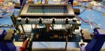
I'm using a single 28x2 chip running at 64mhz with an external crystal to handle all task's which include:
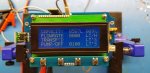
20x4 Display
Multiple Button detections
Ultrasonic module data
Bluetooth data for an App
Controlling a Pump and Valve
Sounding a beeper, all in a big loop that seems to work ok.

I have been using the COUNT command to integrate a flow sensor into the project. It also counts liters pumped and stops pumping when the programmed amount of liters is reached. My problem is that using the COUNT command is only accurate using a long count period but this interferes with the loop in processing other task's. I've been playing around with the PULSIN command but haven't figured out the math's needed to make it work. Could someone be able to give me a few pointers in the right direction? I'm not sure if PULSIN would even work seeing that it does not measure the period, only the length of the pulse. I have included a PDF of the sensor used. I'm working on the basis of a 50% duty cycle...

Cheers, Kurt
 

Attachments

Last edited:

AllyCat

Senior Member
Hi,

Normally, the simple* solution would be to use an interrupt, but this may depend on the maximum number of pulses per second being generated, and perhaps the specific PICaxe instructions being used in your main polling loop. *Alternatively, there are various "hardware assistance modules" on the PIC{axe} silicon chip, but they're likely to require a much more intimate understanding of how everything works.

The data sheet shows a graph up to 120 Hz (or pulses/sec) and even that speed may be possible; The 50% duty cycle is "good news", so basically it would be necessary to support 240 interrupts/sec, or one every 4 ms (also known as the "latency" of the interrupt), being alternately triggered by 0 -> 1 and 1 -> 0 logic edges. The interrupt would only need to increment a variable (count), then adjust the interrupt "mode" and Return, probably taking less than 1 ms each time (at 64 MHz).

A "problem" may be in avoiding all "blocking" instructions in the main loop, because these may lead to interrupts being "missed". Particular areas of concern might be writing long strings of characters to the display, or sounding the bleeper. Also, commands such as ULTRA automatically switch the PICaxe down to an 8 MHz clock, which may introduce excessive delays. Therefore we may need much more detail about the specific instructions being used and the timing in your program.

Cheers, Alan.
 

hippy

Ex-Staff (retired)
Staff member
The 50% duty cycle is "good news"
I wasn't entirely convinced the data sheets stated that though I'm not entirely sure what it is saying -

"The output pulse duty ratio : In the rated voltage, the output pulse occupies emptiescompared to 50%-10%"

I would also have suggested interrupts but then one perhaps needs to determine what the period is between pulses which isn't always simple.

How easy it would be to move from COUNT to PULSIN or interrupts would possibly depend on how the COUNT value is used, whether that can easily be changed to a PULSIN or interrupt measure.

An alternative would be to use an 08M2 as the pump counter then the main code can poll to see if there is a count available and read it without having to wait until a count is available.
 

AllyCat

Senior Member
Hi,

Yes, the data sheet is very much in "Chinglish" and I'm not even sure if it uses a Hall effect or Reed switch. Indeed, we ideally need some "real numbers" to create an optimum design concept, but here is an alternative approach that I was already drafting:

If you really want to use PULSIN , then you could use two consecutively, to measure the High and Low periods separately (their ratio might be a "constant" for the sensor, which could be incorporated into the final program, but let's assume that it is measured every time). This will take up to two cycles (or COUNTs) of the waveform. However, if a pulse isn't detected within 41 ms (at 64 MHz clock) then a timeout will occur and a "0" will be returned. This must be interpreted in the same way as a COUNT = 0, so you might need to reduce the clock frequency to extend the timeout period.

If both values (High and Low pulses) are both valid, then they need to be added to give the period, but that calculation could overflow, so divide by at least 2, but probably better to scale to (say) 0.1 ms units by dividing by 100 / 0.625 = 160. Each division should give a value in the range 0 - 409 , so added together gives a range of 0 - 816 (call it "period"), or you might want to divide instead by 640 to give a final value that fits within a byte.

Then you can calculate the "COUNT" (per second) by dividing 10,000 by "period" (because 10,000 is the number of 0.1 ms units in 1 second). Or 2500 or similar factors if you've used other scale/frequency values. However, I have not thoroughly checked/tested this method and the numbers, so "E&OE". ;)

Cheers, Alan.
 

erco

Senior Member
Great opportunity to use old school analog circuitry if you're up for some experimental calibration. Sensor output pulses trigger a 555 one-shot which charges a calibrated RC pair. Voltage on the pair is directly proportional to flow rate, read instantly with READADC.
 

inglewoodpete

Senior Member
Great opportunity to use old school analog circuitry if you're up for some experimental calibration. Sensor output pulses trigger a 555 one-shot which charges a calibrated RC pair. Voltage on the pair is directly proportional to flow rate, read instantly with READADC.
The problem I see is that @johndo has not indicated the range of pulse times that are expected from the sensor. DtoA is fraught with non-linearity with very low pulse rates due to discharging of the capacitor.

If it was possible I would be using interrupts, after removing any blocking commands. That means avoiding serin, sertxd and serout as well and using background hSerial input and output. The ultrasonic input sounds like a blocker in more ways than one. This might be a job for two 20x2s rather than one 28x2.
 

PhilHornby

Senior Member
I have been using the COUNT command to integrate a flow sensor into the project. It also counts liters pumped and stops pumping when the programmed amount of liters is reached.
So is it actually volume you're concerned with - rather than flow rate ❓
The data sheet shows a graph up to 120 Hz (or pulses/sec) and even that speed may be possible; The 50% duty cycle is "good news", so basically it would be necessary to support 240 interrupts/sec, or one every 4 ms (also known as the "latency" of the interrupt), being alternately triggered by 0 -> 1 and 1 -> 0 logic edges. The interrupt would only need to increment a variable (count), then adjust the interrupt "mode" and Return, probably taking less than 1 ms each time (at 64 MHz).
Why does it need to track both the rising and falling edges of the pulses ❓
Sensor output pulses trigger a 555 one-shot which charges a calibrated RC pair.
This might be a job for two 20x2s rather than one 28x2.
The Picaxe 08M2 is the same size as a 555 timer :)

I'm sure an 08M2 could be used to turn on a pump, until a certain volume of water has flowed - that volume being ascertained by counting pulses using an interrupt. The count may require a multi-precision (i.e >16bit) variable, but at 32MHz, I reckon the 08M2 could handle an interrupt every 8mS)
 

AllyCat

Senior Member
Hi,
Why does it need to track both the rising and falling edges of the pulses ❓
AFAIK, the (M2) interrupts are (only) Level-Triggered, so before RETURNing, the routine either must wait until the triggering level has terminated (potentially a considerable waste of time) to prevent false re-triggering, or the (next) interrupt level must be inverted. Hence two interrupts for each cycle.

That said, I would still consider the whole project probably could be done by a single PICaxe with little, or no, external hardware "assistance".

Cheers, Alan.
 

PhilHornby

Senior Member
AFAIK, the (M2) interrupts are (only) Level-Triggered, so before RETURNing, the routine either must wait until the triggering level has terminated (potentially a considerable waste of time) to prevent false re-triggering, or the (next) interrupt level must be inverted.
Ah, yes, I see. Presumably to use that scheme, the input pulse has to last for a certain minimum time (i.e. long enough to get the 'reverse' interrupt set up, so the trailing edge isn't missed.)

Maybe a pulse-shortening capacitor/resistor combo on the input would be a viable alternative? Or perhaps the Interrupt-on-Change flags are a better bet?
 

johndo

Member
Thank you all for your replies...

The main loop is very busy doing all kinds of serial TX & RX to the bluetooth module and the ultrasonic module and also writing to the LCD display,
this cannot be altered.

I'm not using the "ultra" command but rather using serial to send commands and receive distance measurements from the ultrasonic module.

I've tried using interrupts in the main loop but haven't had much luck. The only way I can get accurate flow rate readings and with adequate resolution is to have a very tight
sub-loop within the main loop using the count command which renders the whole loop useless as there is a relatively long pause before the code can proceed.

Code:
for b0=1 to 100
count B.0,160,w1
next b0
gosub flowrate  'writes to LCD etc...Then continues through main loop
Pulsin works without blocking so interested if this could somehow be implemented?

Your thought of issuing two consecutive pulsin commands sound interesting Alan, will try.

Hippy yes I have thought about using a separate 08m2 chip exclusively for the flow rate but the one chip solution does appeal to me.

I'm quite embarrassed about posting major parts of the code but I assume you get the idea...

Cheers
 
Last edited:

hippy

Ex-Staff (retired)
Staff member
Pulsin works without blocking so interested if this could somehow be implemented?
PULSIN is blocking, though its timeout will be shorter than COUNT.

The main loop is very busy doing all kinds of serial TX & RX to the bluetooth module and the ultrasonic module and also writing to the LCD display,
this cannot be altered ... I have thought about using a separate 08m2 chip exclusively for the flow rate but the one chip solution does appeal to me.
If you have arrived at a design which won't work in practice you may have to consider a change in that design.
 

AllyCat

Senior Member
Hi,

IF the flow rate is reasonably constant and the Main Program Polling loop is quite fast, then simply sampling the flow rate in the main loop (with two PULSINs) may be sufficient. IF (also) the Polling Loop has a reasonably constant cycle time, then the calculation (i.e. integration) of the flow rate (to obtain a total volume) may be reasonably easy. BUT if the loop time is not constant, then the calculation/timing may become too complex and another solution may be necessary.

Maybe a pulse-shortening capacitor/resistor combo on the input would be a viable alternative? Or perhaps the Interrupt-on-Change flags are a better bet?
It's looking as if Interrupts may not be the best solution here, but "Bistable" Edge-Triggered Hardware or Software might be used (perhaps the S-R flip flop). One polarity of edge would flip the Bistable to generate the Interrupt and the Program Interrupt code then cancels it before RETURNing. Bear in mind that (at least with M2s) the Interrupt On Change bits are only flags. In M2s, an interrupt can be generated ONLY by a level change on a Physical Pin, not by anything that needs to be polled. A "monostable" (e.g. pulse-shortening) detector may have a problem that the signal "vanishes" before the interrupt is detected (because with PICaxe Basic the interrupts are only polled).

Cheers, Alan,
 

hippy

Ex-Staff (retired)
Staff member
I
I have been using the COUNT command to integrate a flow sensor into the project. It also counts liters pumped and stops pumping when the programmed amount of liters is reached.
If I understand that right you are simply wanting to count the pulses, each pulse representing some quantity of sub-litres which has passed through, and, as soon as enough sub-litre pulses have been counted, the tank is as full as you want it, you turn the feed off, job done.

In which case you are only interested in how many pulses there have been, not the rate of those pulses per se. How fast the water is flowing, how fast the tank is filling is irrelevant -- accepting that rate of flow may currently be being used to derive actual quantity delivered in your existing code.

Counting each pulse and adding some quantity to the number of litres which have flowed seems to be the bottom line..

There seems to be four ways to do that beyond using the COUNT you have been using -

1) Polling for pulses - Could be difficult with high speed pulses and you are likely to miss some when busy doing other things.

2) Interrupts on chip - You should miss fewer than polling but there may still be some missed.

3) Incrementing an on-chip counter peripheral - That should be achievable using a timer with its clock fed from the flow meter and should have zero misses.

4) Using an external 08M2 to do the counting and passing the count to the main chip in an expedient manner. That should be doing little so shouldn't miss any whether polling, interrupt or on-chip counter based.

To me, (3) looks like the best option; on-chip counter. There are three 16-bit timers which would seem to be able to do the job, give three possible options for flow pulse input which could help avoid hardware connection changes..

Update : That seems to work - https://picaxeforum.co.uk/threads/on-chip-counters-using-28x2.32632
 
Last edited:

Flenser

Senior Member
Counting each pulse and adding some quantity to the number of litres which have flowed seems to be the bottom line..
It looks to me like Hippy has it right. The chart in the datasheet attached to post #1 shows what looks to be a straight line relationship between the freq of the pulses in Hz and the flow rate in l/min. That means that each pulse represents a fixed volume of fluid.

It also counts liters pumped and stops pumping when the programmed amount of liters is reached.
johndo, Your datasheet also gives the formula "Flow pulse characteristics" = [4.1Q] +/-10%
That +/- 10% means that you will only get a rough measure of the the flow rate and volume being delivered by the pump.
- If your unit is reporting a lower volume than it is actually being delivered then your plan to stop pumping when the programmed liters have been delivered will eventually overflow the tank.
- If your unit is reporting a higher volume than it is actually being delivered then your plan to stop pumping when the programmed liters have been delivered will eventually cause the tank to run dry.
- You can calibrate your unit but that will not remove the error, it will only reduce the error range to a smaller value. It will take longer for the tank to overflow or run dry but the outcome will probably be the same.

Is there a reason why you can't use a float valve, like in a toilet cistern?
 

PhilHornby

Senior Member
This was a reply to a message that seems to have mysteriously vanished :unsure:

The solution @hippy documented would be more than capable of measuring the volume delivered (as a background activity). However, you haven't confirmed that that is what you actually want to measure...

But as @flenser implies, you seem highly likely to underflow or overflow the tank, without some sort of level detection.
 
Last edited:

johndo

Member
2533125332
The solution @hippy documented would be more than capable of measuring the volume delivered (as a background activity). However, you haven't confirmed that that is what you actually want to measure...

But as @flenser implies, you seem highly likely to underflow or overflow the tank, without some sort of level detection.
@hippy
@Flenser
@PhilHornby

Thank you for your continuing interest in this thread. Been asleep downunder for the last 8 hours :)

This is my setup on the bench ATM. I would like to display both LPH or LPM & TRANSF'D being the total pumped.

The idea from Hippy that it's as simple as each pulse representing a fixed volume of liquid is an excellent example of logical thinking that evades me most days... (EDIT) Just wanted to add that I have an DS3232 RTC on board (middle RHS). This will be used to log tank levels each minute/hour/day and then store on an onboard eeprom. It just so happens that I have the 1HZ output pin of the RTC connected to INT1. I designed the board quite some time ago and had forgotten about this feature. This could work right?

The idea behind the project is to program the controller to pump a required amount of water from a rainwater tank to fill the pool or water the garden. It's not essential that its super accurate but my OCD takes over most times.

I hope this helps explain things a little better.

PS: The bluetooth module at the very top of picture is the implementation of @Goeytex excellent work on @manuka's recent thread RE: Wireless Programming? It works a treat and I only have the hardwire programming cable connected for speed of download as the wireless option is a little slow for work on the bench.

Cheers, Kurt
 
Last edited:

Flenser

Senior Member
Kurt,

It occurred to me later on that I could have gotten the pumping direction the wrong way around.

If you have one of the required pin's free then Hippy's suggestion #3 looks like a good candidate because it doesn't require any extra BASIC code to monitor the pumping progress (and so will have no impact on the existing code) and because it uses the PIC counter hardware it won't miss any counts (and so is likely to give you the most accurate count)
At some point in your existing program you decide water needs to be pumped out and:
if PUMP_RUNNING=FALSE
1) start the hardware counter
2) start the pump
3) set some variable like PUMP_RUNNING=TRUE
endif

Then in your main loop you add something like:
if PUMP_RUNNING=TRUE then
read the hardware counter value
if the counter value is > the volume you wanted to pump
1) stop the pump
2) optionally stop the hardware counter
3) set PUMP_RUNNING=FALSE
4) add the hardware counter value (which is the actual value pumped) to your "transferred" running total
endif
endif

And test to see if the overhead of this extra code in your main loop interferes with the loops other task's.
 

hippy

Ex-Staff (retired)
Staff member
And test to see if the overhead of this extra code in your main loop interferes with the loops other task's.
Pretty much what I would have suggested and I doubt it adds any significant overhead to the main loop. No more than any other solution would.

I can understand wanting LPM and LPH if it takes a long time to fill something. I am sure than can be done by zeroing the count when the pump starts and remembering the time, then calculating those from "count divided by elapsed time multiplied by some K".

I guess that's average more than instantaneous so you could perhaps have a list of 60 counts and shift them down every second, then the minute rate is last minus first, hour rate that times 60. You can sample less frequently and have a shorter list.
 
Top