Flow Logger

Jeremy Leach

Senior Member
Ok, here's my best shot. Simplified now by using a right-angle and hall effect sensor. Obvious advantage over my last one is that the 'rod' can be anything, as long as it fits fairly snugly into the tube. I'd imagine it's best to keep the vertical travel quite small if using a hall effect sensor. Perhaps getting the right angle might be difficult in practice?
 

Attachments

Last edited:

Dippy

Moderator
Make one Jer. I can see your thinking but I reckon it will behave strangely with water all around your rod.
Tell us the results.

Who was it who said "Don't talk - eat!" :)
 

Jeremy Leach

Senior Member
Yes, but a bit of thinking time up front will save hours of time later. I've got to get a good, practical solution in my head before I'll even bother giving it a go.

I think you might be right on the water swirling around the rod Dippy, but can't tell that one until put into practice. But what I'd like to know is the recommended travel for the magnet and a suitable cheap hall effect sensor. Plus, anyone's thoughts on the inductor idea and whether it's feasible and any example oscillator circuits?!
 

Dippy

Moderator
"Yes, but a bit of thinking time up front will save hours of time later. I've got to get a good, practical solution in my head before I'll even bother giving it a go. "
- I agree 100%

"but can't tell that one until put into practice"
- Sometimes what looks nice when circulating in the 'grey matter' doesn't work very well in the Real World where you will have unknown fluid speed, pressure etc. What happens when a tap is turned on/off on the outflow? Not to mention laminar and turbulent thingies.
Hence my suggestion to prototype.
Trouble is that when it gets to engineering then it can be pricey and/or fiddly and a cheap bodge may be awful but the same thing made properly works beautifully.

"recommended travel for the magnet and a suitable cheap hall effect sensor"
- depends on sensor and magnet.
The temptation will be to buy the cheapest lump from Ebay, but maybe a few extra pennies could turn trash into genius...?

"anyone's thoughts on the inductor idea"
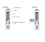
- I preferred that overall design, maybe in a tapered tube like the Big Boys do.
Its a bit like DPG's but elastic is replaced by gravity.
The Big Boys obviously spent more than 10 minutes on the problem and more than 10p on prototyping. Maybe substitute 'obviously' with 'hopefully' :)
As your inductance changes may be quite small I would lean towards either:-
1. Good old BFO design to maximise small changes. As used in cheap metal detectors.
2. An oscillator design, square it up and use PICAXE to count pulses.
Long term stability can be a problem with simple circuits.
Sorry haven't got any circuits to hand.
 

BeanieBots

Moderator
My thoughts too Dippy.
Tapered tube with 'pointy' float as used by all (visual) flow meters I've ever seen.
I have some air flow meters which use a sphere but still in a tapered tube.
My only water flow meter uses a simple water-wheel method with a magnet and reed mechanism.

I like the coil idea and would also suggest looking up metal-detector circuits.
Another thought would be to have two coils bi-filar wound.
The 'plunger' would then increase/decrease the coupling.
Drive one with a constant amplitude signal. Use the other (via a simple detector circuit) to measure the amplitude of the coupled signal.
 

Jeremy Leach

Senior Member
Hmmm, I've found what I need for a tapered solution - a few plastic plumbing bits (inc T junction) and nylon washers, and a nicely tapered nozzle from a glue dispenser !! It might take me a while to get it into something workable, and I expect there will be issues :) I'll aim to try the coil idea as part of it.
 

nbw

Senior Member
Have I understood it right Jez - the main flow goes through a 90 deg bend? That will impede and lower water pressure. I get that a lot with my aquariums - the more bends in the PVC pipe for the water pumping - the less pressure at the end (v important for live corals).
 

Jeremy Leach

Senior Member
Yes, my last attempt goes through 90 degrees. I can see what you're saying ... (I remember doing a module on fluid mechanics at Uni years ago!). I'm just wanting to see what's possible to build cheaply from off-the-shelf items from a hardware store. I basically like proving that you don't always need to spend £££ to get acceptable results ;)

However the 90 degrees might not matter if the flow meter isn't in the main pipe. What I mean is this:

In the manometer link in a post above, the main pipe diameter changed and this gave a differential in pressure at two outplet points. If you connect these outlet points then you'd get a flow between them.

So I was thinking that you could have the flow meter in this side channel rather than in the main pipe. The flow rate would be a lot lower, and you'd have to calibrate the whole thing, but perhaps it would offer some advantage when it comes to things like 90 degree bends because a 90 degree solution wouldn't matter so much at lower flow rate? Also it might be good to have the whole flow meter out of the path of the main flow? I'm no expert here, just thinking out loud !

If I do get my prototype working though, I'm not going to bother with side channels - I'll stick it in the main flow to my lawn sprinkler and see what happens, even with 90 degrees ;)
 
Last edited:

QuIcK

Senior Member
use a venturi tube. its a constriction in the pipe with a presure meter before, and a pressure meter in the middle of the constriction. pressure difference is related to flow rate with de broglies theorem (or is that magnetic flux? no wait, electron quantizing is de broglies.... whats the one for pressure? bernoulli, i think)
surely there are cheap pressure sensors... a cheap condesor microphone would work, mayb too sensitive tho (its a capacitor, with a preamp attatched and generates a voltage from sound waves, so anything), i think they can handle up to 20Pa (mayb could be pushed to 30/40Pa, check the table at the bottom of http://en.wikipedia.org/wiki/Sound_pressure_level)
http://en.wikipedia.org/wiki/Venturi_effect
 

nbw

Senior Member
Would be interesting to see if a relatively cheap DIY solution can be PAXed out of this. Like mentioned earlier, Jaycar have flow sensors - about 20 pounds which is a little pricey, but understandable given what they do. Some great ideas here folks!!
 

QuIcK

Senior Member
Jeremy,
the coil would only give a voltage when the magnet is moving.
other wise we would have free electricity by chucking a magnet in a coil. as opposed to burning coal, to heat water into steam, to drive a turbine, to move a magnet in a coil.

you could use 2 coils, and treat the set up like a variable transformer. low voltage ac through the outside coil, wires into the internal coild. the water pushes the internal coil into outer coil... the farther in, the more current/voltage is induced, thus can be rectified & smoothed, and read by ADC
 

Dippy

Moderator
Think you've got wrong end of stick Quick.

The (single) coil idea was to provide a variable inductor... so could, for example, form part of an osc circuit.

For your second point see Post 45 by BB.....
 

kollinsb

Member
A quick thought. Since there is already a meter there that should be accurate is there a way to capture the pulses through there. If I'm not mistaken there is a clicking noise when the meter is counting. Would it be feasible to count the clicks (with a microphone or something like that) and convert that to gallons? I could then just take the number of clicks in a five minute time frame (or whatever) and calculate from a manually calibrated formula.

Example (hypothetical, not actual data):
  • Testing:
  • 1 gallon=9 clicks
  • 2 gallons=19 clicks
  • 3 gallons=28 clicks
From this we can conclude that 9 1/2 clicks = 1 gallon

If my math is right then that would mean when the interval for the reading comes around the number of clicks is, lets say, 548. Using simple math we can deduce that #gallons=548/9.5 which is 57.68 gallons during that interval.

Am I oversimplifying it or is there just not a good way to use the existing meter (or backflow even) to take an accurate measurement?

Thanks for all the great input!!!
 

Andrew Cowan

Senior Member
I presume this is a meter that belongs to the water board, and can't be hacked. Like a gas meter. However, adding a microphone would be OK.

A
 

kollinsb

Member
I paid $700 to have it installed. I would think it would be mine but with the way the government is these days it may have been part of a bail-out plan or something... lol.

Anyway, this wouldn't require hacking it. I would just have a microphone (or whatever) on the under side (or somewhere close) listening for clicks. When it clicks, the count would increase by 1 and store it. When it was read the counter would be set back to 0 or I could set it to 0 1 time a week or something.
 

demonicpicaxeguy

Senior Member
eeerrr (cringes) i'm not sure how much succes you'll have with a micro phone, strapped to a mater meter , stick your ear against it when the water is rushing through and you'll see what i mean, all the microphone will pick up is a high pitched "white noise" type of sound

you'll find that there will be a place somone near the counter mechanism that you can install a reed switch or hall effect sensor, most water meters that are used residentially are magnetically coupled to the counter and you'll find the spot or most likely a small hole is hidden by some kind of plastic bung to the keep dirt out, or a slot in the front of the counter (see picture of the one below)

can you take a photo of your water meter
 

Dippy

Moderator
My water meter has (mechanical) digital display plus a rotating indicator.
Couldn't some cunning plan be used for that?

I daresay there are a zillion meter designs and as we are sread all across the world then each to their own eh.

How's J coming with the sticky-back-plastic ?

I think I might jut buy one :)
 

demonicpicaxeguy

Senior Member
My water meter has (mechanical) digital display plus a rotating indicator.
Couldn't some cunning plan be used for that?

I daresay there are a zillion meter designs and as we are sread all across the world then each to their own eh.

How's J coming with the sticky-back-plastic ?

I think I might jut buy one :)
if there rotating indicator is black and white or has a slivered and non silvered alternation pattern you'll find the manufacturuer of that meter might be able to supply you with a screw on optical pickup for it
you'll also find that most waters can also take a reed switch as well some of them however require the face which contains the counter tot he removed but you can still get it working in some cases with the reed switch taped to the top
 
Top